zaksignu
-
Composition of system
02/20/2019 at 10:09 • 0 commentsThe main idea of this project - to use parts, which can be bought at ordinary autoshop.
To build up chain oiler you will need
- pump for oil
- shut off valve
- brake hose ( metall one)
- resin oil-resistant hose
- tank for gear oil
---------- more ----------At first i wasn`t think about shut off valve. i thought, that pump`s mechanism will be sufficient to shut off gear oil. I was wrong =). At second i forgot about oil-resistant hoses and they dead in 2 days. it was fun to step on the rake.
So current appearance of system -
oil from tank sucked by pump through oil-resistant resin hose to valve. With excess pressure gear oil pass through valve, move through adapter to metal brake hose. Metal hose comes under swingarm to rear wheel.There is a tee at the end of swingarm.It allow oil comes through hoses to 2 sides of rear sprocket. From lateral face of sprocket oil under centrifugal force thrown into chain. Metal hose is attached to swingarm with 2 3d printed brackets.
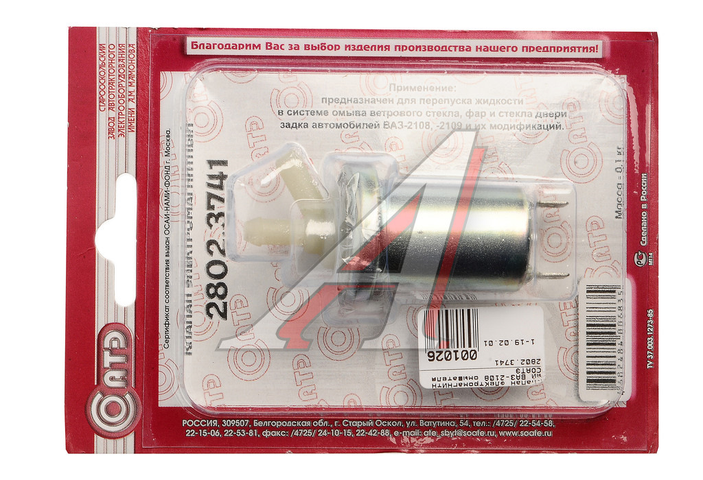
As a pump i used pump for window washer from VAZ 21093 .To see in Google
![]()
As a shut off valve i choose valve for rear window washer from VAZ 21093 .To see in Google
![]()
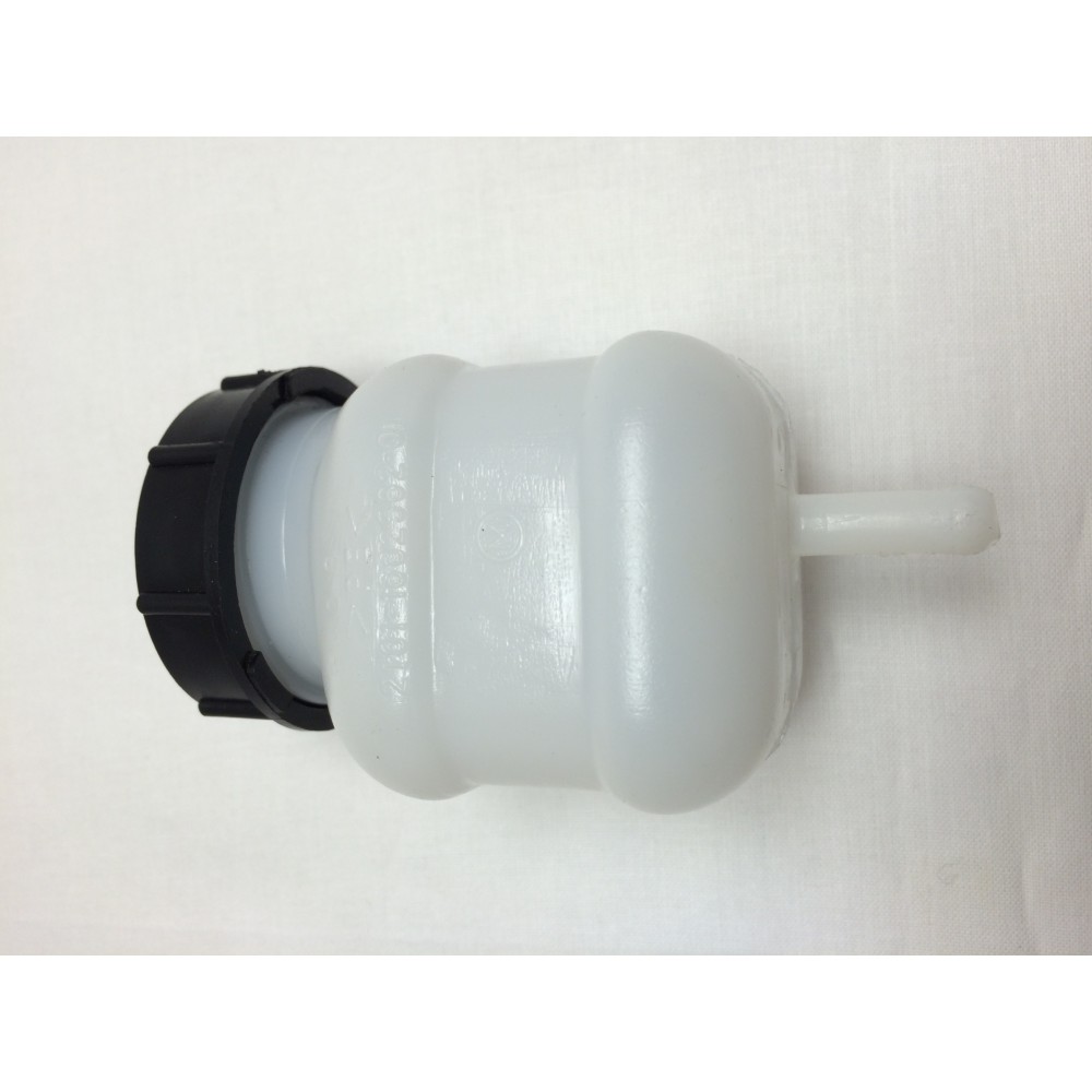
As a tank i used clutch tank from VAZ 2101. To see in Google
![]()
Such semi transparent tank suitable for oil level contol with optical metod.
-
Status mode description
02/20/2019 at 07:52 • 0 commentsThereis 7 status mode:
- max oil level ( its normal state)
- medium oil level( its normal state)
- a little oil level( its normal state)
- flow state ( it is special state)
- no current state ( its not normal state)
- overcurrent state ( its not normal state)
---------- more ----------Let`s describe it carrefully
- max oil ( its normal state) . Nothing to do with it. 2 green flashes.
unsigned short int maxoil[5][2] =
{
{0, 1},
{0, 0},
{0, 1},
{0, 0},
{0, 0},
};
- medium oil level ( its normal state) . Nothing to do with it. 1 red - green flash and green flash.
unsigned short int someoil[5][2] =
{
{1, 1},
{0, 0},
{0, 1},
{0, 0},
{0, 0},
};
- a little oil level( its normal state) . It need som attention. 2red - green flashes.
unsigned short int littleoil[5][2] =
{
{1, 1},
{0, 0},
{1, 1},
{0, 0},
{0, 0},
};
- flow state ( it is special state). there are couple of cases during my mototrips, when i needed an additional grease for my moto chain ( extrem wet condition, rain, overnight stop after rain). So, it is very usefull to have constant flow for chain lubrication. Indicating of this state - constant green led.
unsigned short int flow[5][2] =

{
{0, 1},
{0, 1},
{0, 1},
{0, 1},
{0, 1},
};
- no current state ( it is state of error). Look like something is wrong, then MOSFET is opened, but there is no current ( or current is below minimal). It can be run out of oil, pump or valve failure, or wire break. It flash 2 times with red led
unsigned short int nocurr[5][2] =
{
{1, 0},
{0, 0},
{1, 0},
{0, 0},
{0, 0},
};
- overcurrent state ( its not normal state). Look like something is wrong, then MOSFET is opened and current much more than normal. It can be shortcircuit, pump or valve jamming. It flashes 1 times with red and 1 time with greem
unsigned short int overcurr[5][2] = { {1, 0}, {0, 0}, {0, 1}, {0, 0}, {0, 0}, }; -
TIM2 routine
02/20/2019 at 06:57 • 0 commentsTIM2 fires every 500ms. It has :
- routine to define input variables (oil_level, wet_state, flow_state flags)
- routine to define exact state of working cycle
- routine to define flow_mode flag
- routine to define currents of mosfets ( project)
---------- more ----------Simple explanation of TIM2 cycle - at the random moment with flow_state = 0. There is 4 possible states :
- we are inside idle state ( curr_tick < idle_tick , do nothing, just curr_tick++)
- we are at the end of idle state ( curr_tick => idle_tick, we must open
MOSFETS anddrop to zero idle_state flag,curr_tick ) - we are inside work state ( curr_tick < work_tick, do nothing, just curr_tick++)
- we are at the end of idle state ( curr_tick => work_tick, we must close
MOSFETS ,drop to 0 curr_tick , fire ip idle_state flag to 1 )
{ //routine to define input variables ADC_measure(); status_determ(); // on flow_state = 1 we just open mosfets, else find out where curr_tick comes - idle_tick or work_tick switch (flow_state) { case 1: PB_ODR_bit.ODR0 = 0; PD_ODR_bit.ODR0 = 0; curr_tick = 0; idle_state = 1; case 0: if (idle_state == 1) { PB_ODR_bit.ODR0 = 1; PD_ODR_bit.ODR0 = 1; } if (idle_state == 0) { if (curr_tick >= work_tick) { PB_ODR_bit.ODR0 = 1; PD_ODR_bit.ODR0 = 1; curr_tick = 0; idle_state = 1; } else { curr_tick++ ; }; } else { if (curr_tick >=idle_tick) { idle_state = 0; curr_tick = 0; PB_ODR_bit.ODR0 = 0; PD_ODR_bit.ODR0 = 0; } else { curr_tick++; } }; } }; -
TIM 4 routine
02/19/2019 at 16:38 • 0 commentsMain flashing cycle contains 5 TIM4 tick. During TIM4 ticking, orderstate variable moves from 0 to 4 and returns to 0.
orderstate
0 1 2 3 4
|250мс|250мс|250мс|250мс|250мс|
------------------------------------------------------
||||||||||||||| |||||||||||||||||---------- more ----------{ switch (flow_state) // looking for flow state { case 1: // switch FLOW ON if (PB_ODR_bit.ODR2 == 0) PB_ODR_bit.ODR2 = 1; case 0:// switch FLOW OFF if (PB_ODR_bit.ODR2 == 1) PB_ODR_bit.ODR2 = 0; } switch (oiler_status) // looking for global status and fire led { case _idle: PB_ODR_bit.ODR7 = idle[orderstate][0]; PB_ODR_bit.ODR6 = idle[orderstate][1]; break; case _someoil: PB_ODR_bit.ODR7 = someoil[orderstate][0]; PB_ODR_bit.ODR6 = someoil[orderstate][1]; break; case _littleoil: PB_ODR_bit.ODR7 = littleoil[orderstate][0]; PB_ODR_bit.ODR6 = littleoil[orderstate][1]; break; case _nocurr: PB_ODR_bit.ODR7 = nocurr[orderstate][0]; PB_ODR_bit.ODR6 = nocurr[orderstate][1]; break; case _overcurr: PB_ODR_bit.ODR7 = overcurr[orderstate][0]; PB_ODR_bit.ODR6 = overcurr[orderstate][1]; break; case _flow: PB_ODR_bit.ODR7 = overcurr[orderstate][0]; PB_ODR_bit.ODR6 = overcurr[orderstate][1]; break; } if (orderstate >= 4) {orderstate = 0;} else {++orderstate;}; TIM4_SR1_bit.UIF = 0; } -
Main concept for STM
02/19/2019 at 12:37 • 0 commentsMain concept for STM.
There are 2 timers - TIM 2, and TIM4. Period of TIM2 approximately 0.5ms, period of TIM4 approximately 0.25ms. TIM 2 is using for controling MOSFETS, obtaining parameters ( flow status, wet status, oil level) and status updating. TIM4 is using for indicating ( green - red led).
Period of led indicating is 5 TIM4.
0 1 2 3 4
|250мс|250мс|250мс|250мс|250мс|
------------------------------------------------------
||||||||||||||| |||||||||||||||||Thereis 7 status mode:
- max oil ( its normal state)
- medium oil ( its normal state)
- a little oil ( its normal state)
- flow state ( it is special state)
- no current state ( its not normal state)
- overcurrent state ( its not normal state)
- start state ( first run)
so green-red led has different flashing modes with different states.
Moto_oiler
Trying to build my own chain lubrication system with blackjack&etc.