Ever since I first saw a Raspberry Pi, I’ve always had grand ideas of what I could build, if I just, one day, found the time/motivation and learnt what to do.
Then I saw the Pi Zero and the small size seemed to open an even bigger world. More importantly it gave me a brainstorm in relation to a project I’ve always wanted to do.
I’ve always been a fan of Star Trek - The Next Generation and so my project idea seemed to make perfect sense to me. Not only as a way to learn all the skills needed to complete it, from soldering, and electronic components to Python, but as something I’d wanted for a long, long time.
My project idea…. A Tricorder.
I knew it was possible and now the technology made it possible for me. I started searching for components, getting ideas and looking into how python works. I had grand ideas, lots of sensors and more!
I set out with no real goal, other than to make as close a functioning tricorder to the show as I possibly could. To that end it was important for me to ensure that it still looked like a tricorder. I consider 3D printing the case and completing the electronic in CAD. But I quickly realised I had no skills in either 3D or CAD. The most sensible approach was to use a case that already existed.
My mind wandered back to one of my favourite childhood toys, the Playmates Tricorder:
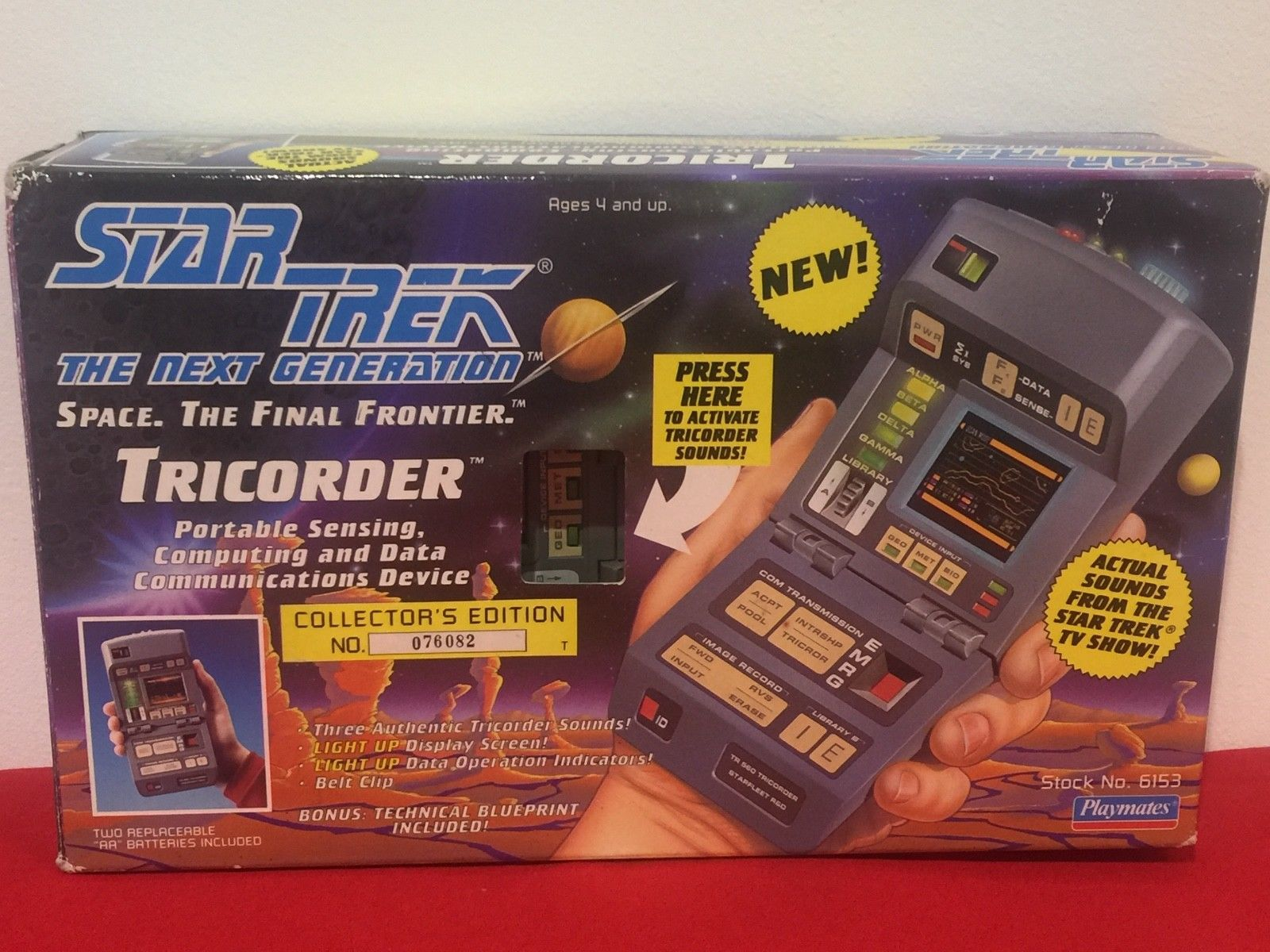
I dug around in the loft and found it, in tact box and all! However, sentiment set in and I couldn’t destroy such an icon from my childhood, so eBay it was.
Can you believe the prices these go for on eBay! I thought maybe £10 or so, but no. Some are upwards of £50. But I found a few auctions and bid on a few and ended up with 3 (just in case I needed spare parts).
Over the next year and a half, in free time, in-between work/holidays/wedding planning and life, I set about building my tricorder.
27th November 20178 - the day I started taking apart the tricorder case and planning what needed removing inside to fit all my components in.
A few tool purchases later and I’d cut and grinded away the bits of plastic casing in my way.
I began to purchase. A Pi Zero W, components, sensors, small TFT screens, power, batteries, amps, speakers, wires, solder, more wires, a breakout board and a pi-cobbler! The latter two would prove invaluable when it came to testing!
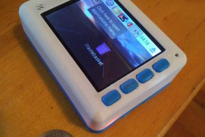
Next came lots of testing, bits at a time. It was a learning curve for me. Trying to get the small TFT screens to work from the GPIO was a real struggle. As was getting to grips with linux and a command line interface. But the testing went on. Testing components, code and how they would fit in the case.
A key goal, right from the start was to have this as close to a real tricorder as I possibly could. I needed the buttons to all be touch sensitive. I found a fantastic capacitive touch sensor to use.
Slowly it started to build up together. I got the python code all working, the screen was working and kind of fit in place. I spent ages, cutting and soldering wires, trying to keep everything small and as neat as possible to make sure it all fit.
I wanted it battery driven. To solve space issues the battery had to be in the lower half of the case. This meant somehow, I’d need to connect the two parts of the case with wires. I was looking into complex solutions and somehow replacing the plastic hinges with different ones to allow for the cables but in the end, it was far too complex. The simple option was to cut two holes. On reflection I could have made a better, and neater job of this, but it works.
The battery sits in the lower half and the ribbon cable connects the buttons to the touch sensor.
After all my grand ideas I could only fit 3 sensors into the case. I chose the AMG88, BME680 and the TMP007. I felt they would give a good range of sensing options for the Tricorder. I wanted to re-design the entire top of the case, incorporating the sensors with LEDs, but again this was a step to far for my skills and...
Read more »


 Dylan Radcliffe
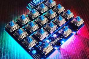
 Mattia Dal Ben
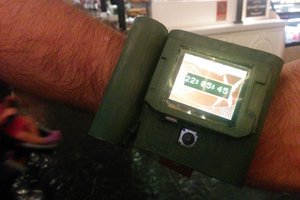
 Christian
 Andy
Andy
Hello Tom, I am working on something just like this currently (just starting, super beginner) and I am waiting for the Tricorder mark IX shell to be printed. I don't know if this is Taboo or not so I'm sorry and will certainly credit you, but are you willing to share any of your assets? Led sizes and other components other than the Pi Zero? If not, thats just fine. I think you did an amazing job!