Alastair Hewitt
-
System Monitor
04/30/2021 at 03:39 • 0 commentsI got a suitably dog-eared copy of 8080/Z80 Assembly Language Techniques for Improved Programming that covers the development of a system monitor in chapter 6.
![]()
The code is also available here, but the book breaks it down into stages so you can build up and debug the functionality step by step. This is invaluable since my 8080 byte-code interpreter is riddled with bugs!
There was some additional work needed before even getting through the first exercise in attaching the console. I needed a way to interface the virtual UART to the 8080 and the most elegant way of doing this was via the input/output ports. The first 8 were assigned to the expansion board, but the rest have now been assigned as follows:
Port# Input Output 0-7 Expansion In Expansion Out 8 Serial Rx Serial Tx 9 Console (KBD) Console (CRT) 10 KBD Scan Codes Set Audio Mode 11 Cursor Character Enable/Disable Rx 12-55 Zero Page Read Zero Page Write 56-63 Zero Page Read Only NOP The system's zero page is not addressable by the 8080, so 52 ports are mapped to this memory space via the ports. The first 44 bytes have read/write access and the last 8 are read only.
PORT  $NAME          ADDR   DESCRIPTION
----  -----          ----   -----------
#SOUND (read/write)
12    $PCMPGH        0x8C # PCM page high water - stop page
13    $PCMPGL        0x8D # PCM page low water - current page
14    $WAVE0         0x8E
15    $ATTACK0       0x8F
16    $DECAY0        0x90
17    $SUSTAIN0      0x91
18    $RELEASE0      0x92
19    $NOTE1L        0x93 # note interval low (FREQL)
20    $NOTE1H        0x94 # note interval high (FREQH)
21    $WAVE1         0x95 # wave table entry (SQRWAV/SAWWAV: 0000WWWW)
22    $ATTACK1       0x96 # ADSR attack (positive 4-bit packed to 8-bits *8: 0AAAA000)
23    $DECAY1        0x97 # ADSR decay (negative 4-bit packed to 8-bits *8: 1DDDD000)
24    $SUSTAIN1      0x98 # ADSR sustain (negative 4-bit packed to 8-bits: 1111SSSS)
25    $RELEASE1      0x99 # ADSR release (negative 4-bit packed to 8-bits *8: 1RRRR000)
26    $NOTE2L        0x9A
27    $NOTE2H        0x9B
28    $WAVE2         0x9C
29    $ATTACK2       0x9D
30    $DECAY2        0x9E
31    $SUSTAIN2      0x9F
32    $RELEASE2      0xA0
33    $NOTE3L        0xA1
34    $NOTE3H        0xA2
35    $WAVE3         0xA3
36    $ATTACK3       0xA4
37    $DECAY3        0xA5
38    $SUSTAIN3      0xA6
39    $RELEASE3      0xA7
#CONSOLE (read/write)
40    $CONL          0xA8 # console left border
41    $CONR          0xA9 # console right border
42    $CONX          0xAA # console column
43    $CONY          0xAB # console row
44    $CONH          0xAC # console height from bottom
45    $CONB          0xAD # console backspace stop
46    $CONC          0xAE # console cursor char
47    $CONF          0xAF # console font
48    $VSTART        0xB0 # start of video display
48    $MODE          0xB1 # video mode to set
50    #SPARE         0xB2 (1)
51    $KTO           0xB3 # max kbd idle count
52    $KSRDIDX       0xB4
53    $KSWRIDX       0xB5
54    $KCRDIDX       0xB6
55    $KCWRIDX       0xB7
#PROTECTED STATE (read-only)
56    $KBSTAT        0xB8 # kbd status
57    #SPARE         0xB9 (1)
58    $BLOCK         0xBA # block count, 0 to 175/160/128
59    $FRAME         0xBB # frame count, -5,-4 to 0
60    $TIME0         0xBC # 15tps, max 90 - 6s
61    $TIME1         0xBD # 10tpm, max 120 - 12m
62    $TIME2         0xBE # 5tph, max 120 - 1d
63    $TIME3         0xBF # 1tpd, max 256 - 0.7y
The console provides a decoded keyboard input and a simple text terminal output to make interfacing easy for the system monitor.
The second exercise in the monitor development was the memory dump command. This is now working after debugging the associated 8080 instructions and arithmetic functions. The following animated GIF demonstrates dumping memory locations 0-300 in real time.
![]()
-
Two Years Later
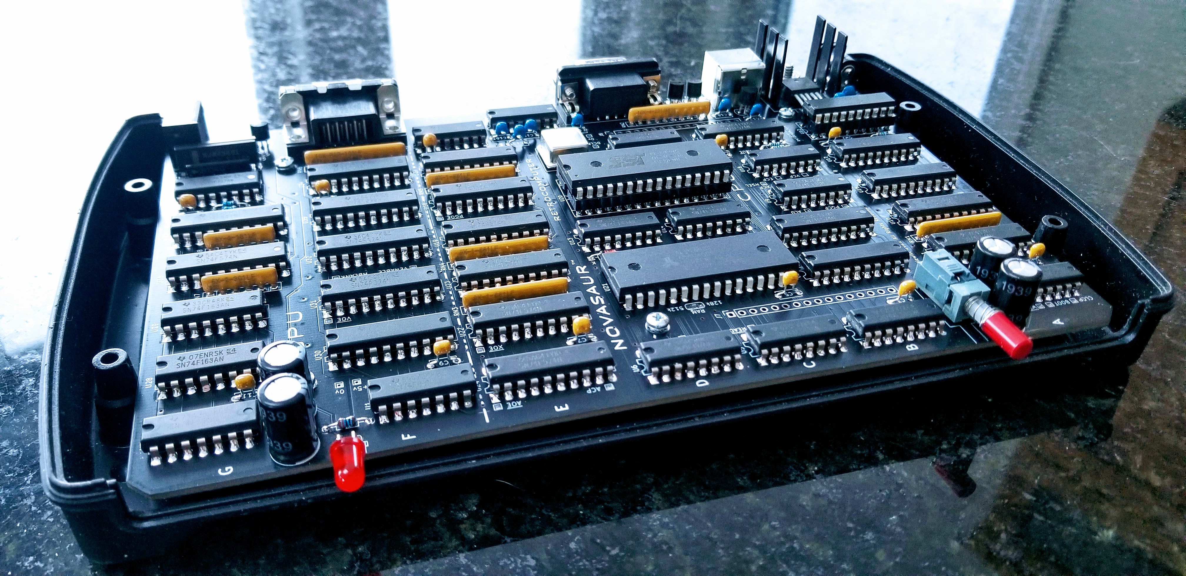
02/22/2021 at 03:45 • 0 commentsIt's been a couple of months since the last update and more like three since anything meaningful changed. There has been (yet) another board revision and Rev. 8 is now good enough to actually solder the chips in place!
![]()
Just like last year, the project is coming out of a design phase and beginning the next stage of development. The past year focused on the firmware (hardware abstraction layer) and this year will focus on the operating system. This primarily involves bringing up CP/M, but there's a bit more to it than that...
Preemptive Multitasking
One advantage of the byte-code interpreter is the CPU state is already in RAM. This makes it easy to switch the CPU context and have more than one CPU running on the machine. The banked memory provides up to 8 banks of 64k and each bank can be assigned to a separate CPU instance.
A counter is incremented at the end of each virtual process block (every 4 lines in SVGA) and the context is switched every 75 blocks. The context is determined by a sequence of 256 that can be set up to prioritize how often each CPU runs. This sequence takes up to 2 seconds to complete, but would typically repeat faster since each CPU can yield before the block count gets to 75.
The context switch takes advantage of the 2-cycle identity function to read/write from the zero page to an adjacent memory location in a single instruction. This allows a entire context switch to be completed in under 80us. The context switch is also the only time the memory bank can be changed and will prevent another process from accessing or modifying another's memory.
This memory segmentation is very important since half the memory banks are used as a disk drive. Without segmentation a crashed user program could write to the memory and damage the file system.
Shared Memory
Bank 0 contains the display and state of the hardware abstraction layer. This state is in a protected area above 0xF0 in the memory and also contains the context for each CPU. There is no context for bank 0, so this is used to hold the context sequence to determine the next CPU context.
0xF0: Context Sequence
0xFn: Context n (1-7)
0xF8: Keyboard Scan Code Buffer
0xF9: Keyboard Character Buffer
0xFA: Serial Receive Buffer
0xFB: Serial Transmit Buffer
0xFC: TBD
0xFD: TBD
0xFE: TBD
0xFF: Zero Page (HAL state)
Each CPU context is broken down as follows:
[0x00 ... 0x7F] [0x80 .... 0xE7] [0xE8 .. 0xEB] [0xEC . 0xFE] [0xFF]
<-record body->|<-message body->|<-msg header->|<-CPU state->| flag
The top 128 bytes is a fixed buffer used for transferring records. The next two sections can contain a message used for inter-process communication; consisting of a variable body up to 104 byes in length and a header containing message metadata. The next 19 bytes contain the CPU state. The final byte is a binary semaphore to signal (0) or wait (-1).
Kernel
Each CPU can only access its own context. However, the first CPU (bank 1) has an additional privilege to access the context of the other CPUs (2-7). This first CPU runs a kernel to manage and coordinate inter-process communication between the other CPUs (master/slave configuration).
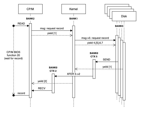
One bank (2) is configured to run the CP/M operating system and the last four banks (4-7) run a process to manage the memory as a RAM disk (designated as the A: drive). The following diagram shows how CP/M would request a record from the RAM disk using a context sequence of 2:1:4:5:6:7:1.
![]()
The CP/M context would publish a message to request a record and then yield. Yielding involves timing out the context block count and setting the semaphore flag to -1 (wait). The CPU is now halted and blocked in the wait state until a signal (0). The context switch would then happen at the end of the current process block.
The next context is the kernel. The kernel operates in an event loop checking the messages from each of the other CPUs (2-7). The kernel sees the message from context 2 (CP/M) and determines which CPU disk instance holds the record. A message is written to that CPU context (e.g. 5) and the flag set to signal. The kernel then yields, but does not halt. The kernel always remains in the the event loop.
The context switches from 4-7 in sequence where most of these CPUs would be halted in the wait state. Context 5 will see the signal though and consume the message. This would result in the record being read and written to context 5 along with a message. This CPU would then yield.
The next context switch is back to the kernel and the event loop. The kernel picks up the message from context 5 and understands this was a request from context 2. The record is transferred from context 5 to 2 and a message is posted to context 2 with the signal.
The final context switch in this sequence is back to CP/M (context 2). The signal has unblocked the CPU and the record is received by copying it to the CP/M file buffer. From the point of view of CP/M, the call to BIOS function 20 returned with the file buffer filled as if it had initiated a request to a disk controlled and then blocked on the IO.
A final note on performance. The record is transferred three times here, but this is done with an extended instruction using native code at one byte per virtual machine cycle. This example requires around 60 process blocks to complete including all the context switching. That's around 6.25ms, or 20k bytes/sec. That doesn't sound very fast, but it's comparable to a floppy disk of the era at around 16k bytes/sec.
The yield and event loops are also handled with extended CPU instructions, so each context switch should fit in a single block. The context switches would take 6 blocks to complete after 75 blocks of CP/M if it doesn't yield. The context switching would therefore account for up to 7.4% of the resources. However, the CP/M process can be extended by adding a null to the context sequence after the context 2 entry (1:2:0:1:4:5:6:7). CP/M would then run for up to 150 blocks before switching and reduce the context switch overhead to just 3.8%.
-
Internet Connection
12/13/2020 at 19:20 • 0 commentsThanks to @Al Williams recent writeup a few questions came up about the Internet connection, "does this have ethernet? Or does it use PPP over that serial line". Well basically, all of the above.
The physical data connection to the board is RS-232-C running at 9600 baud (8-N-1) with RTS/CTS flow control. There's a couple of options from here to get to the Internet. The classical method is via a serial line protocol like SLIP or PPP to a dialup modem. This requires a TCP/IP stack on the machine to handle the rest of the layer-2 and layer-3 network protocol. This would involve porting a stack like uIP and is still some way off in terms of development.
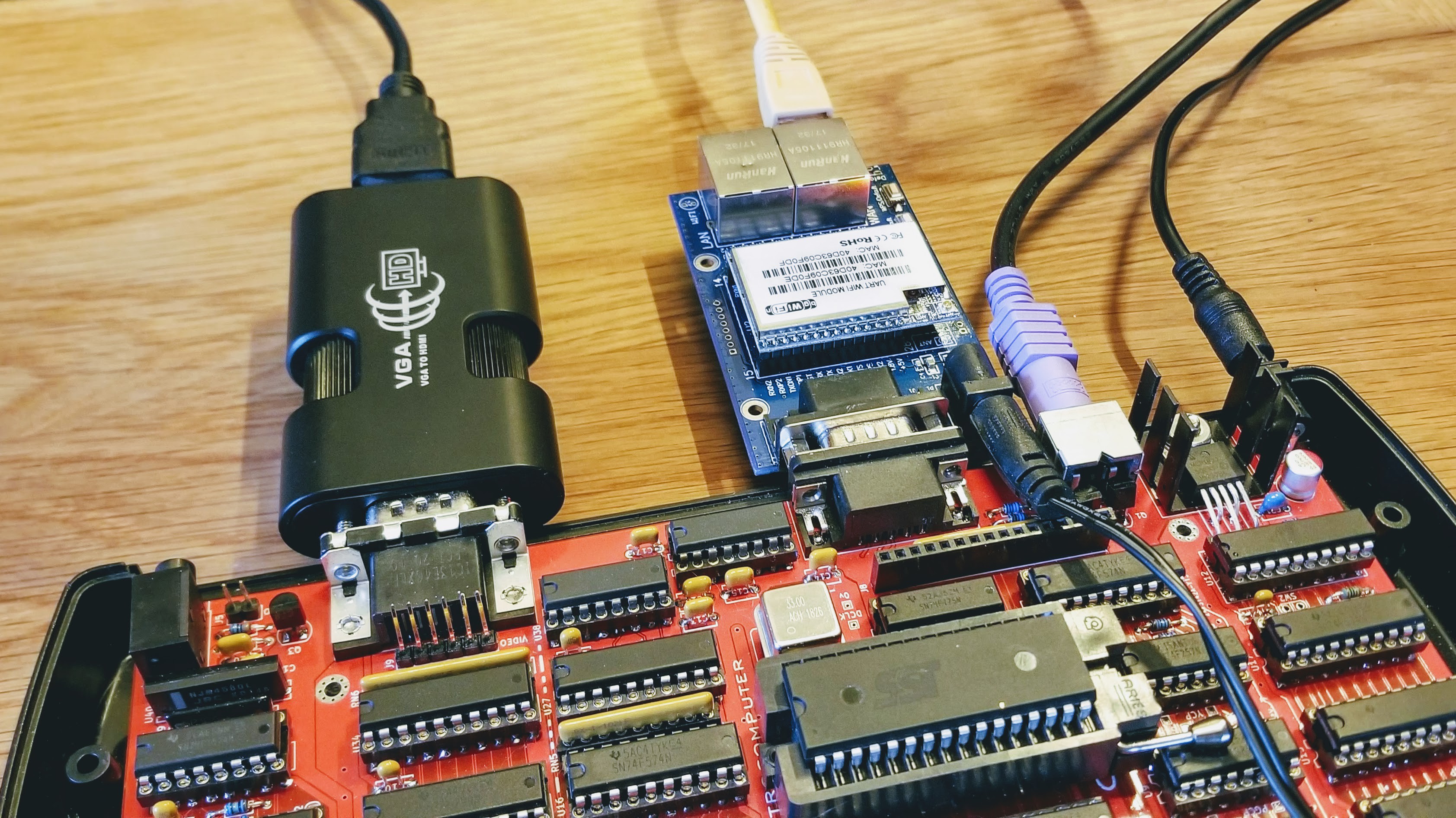
An easier way to connect is via an IoT Wifi/Ethernet-to-UART module. Shown below is the Novasaur with one of these modules to support an Ethernet network connection (also shown with HDMI).
![]()
These modules are a bit of a cheat though. They not only adapt the physical Wifi/Ethernet interface but also contain a micro-controller to handle the TCP/IP connections. The payload is pulled out of the protocol and then sent over the RS-232 like a simple UART serial connection.
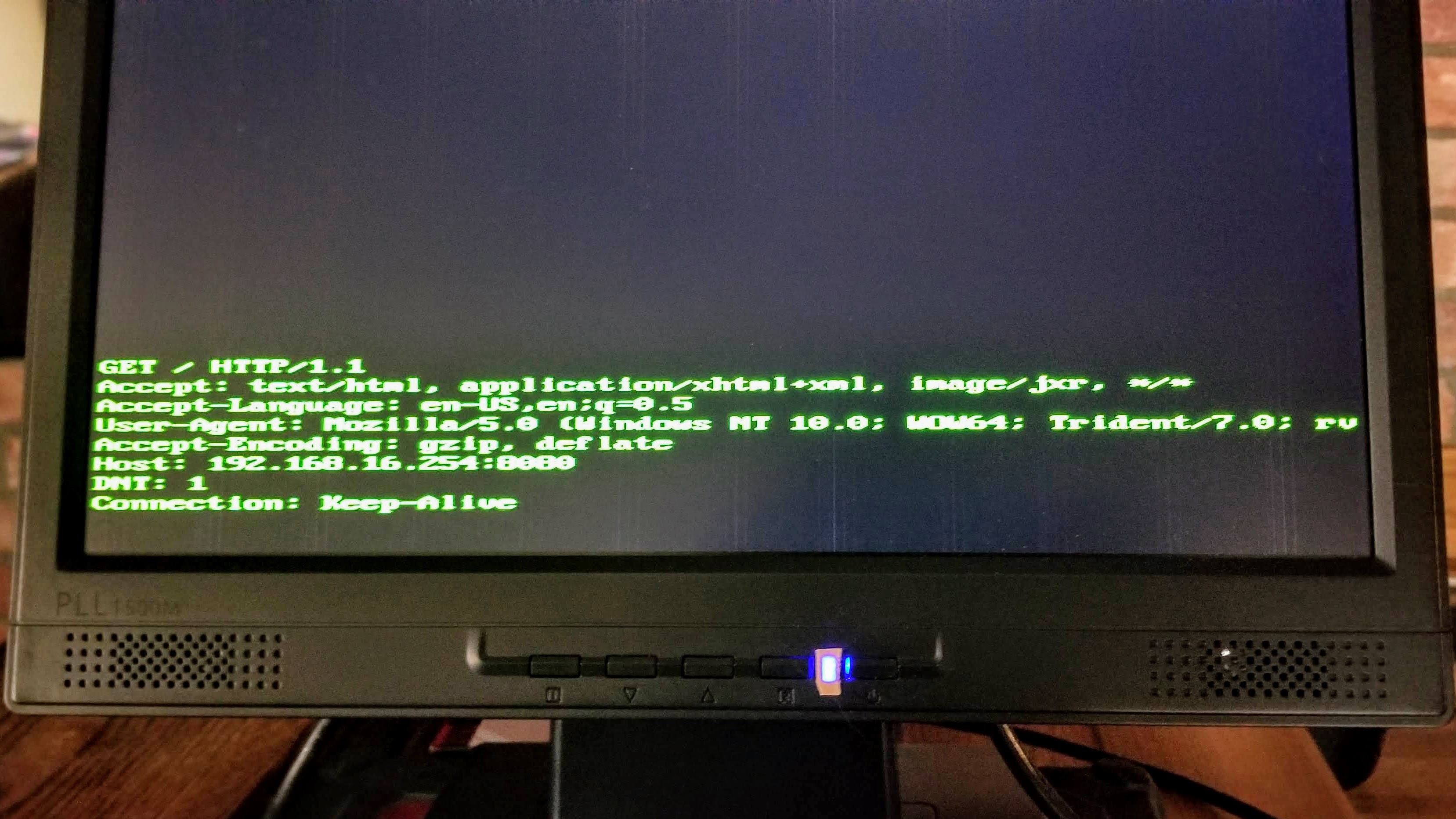
In fact, the current serial terminal program can already display protocols such as HTTP. The (blurry) image below shows a browser connecting to the Novasaur and asking for a web page. The HTTP protocol is just echoed to the screen, but a client program could interpret this and serve up a web page in response.
![]()
A web server is also some way off. The good news is the 8080 CPU is partially tested and running. There's still a lot more to test and plenty of bugs to chase down over the next few weeks. After that a simple monitor program can be added and the work to bring up CP/M can begin.
-
Serial Terminal
11/25/2020 at 00:04 • 0 commentsThe first step in the serial terminal development was to echo characters typed on the keyboard to the screen. The new receive code is now integrated and echos text received over the RS232 serial interface to the screen as well.
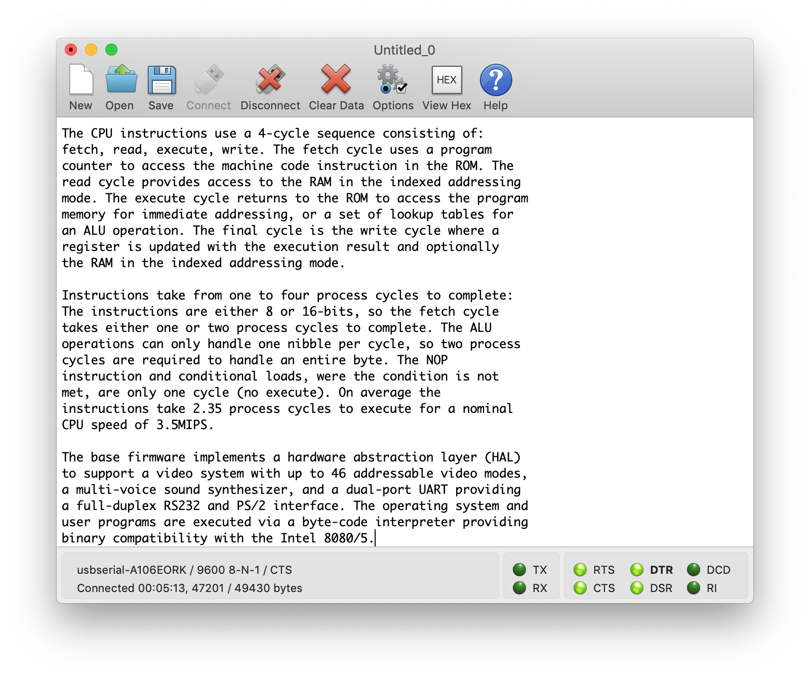
The animated GIF below shows text being received over the serial connection at 9,600 baud, or 960 bytes per second. The text is 2.4k bytes and takes about 2.5 seconds to transfer (shown in real time).
![]()
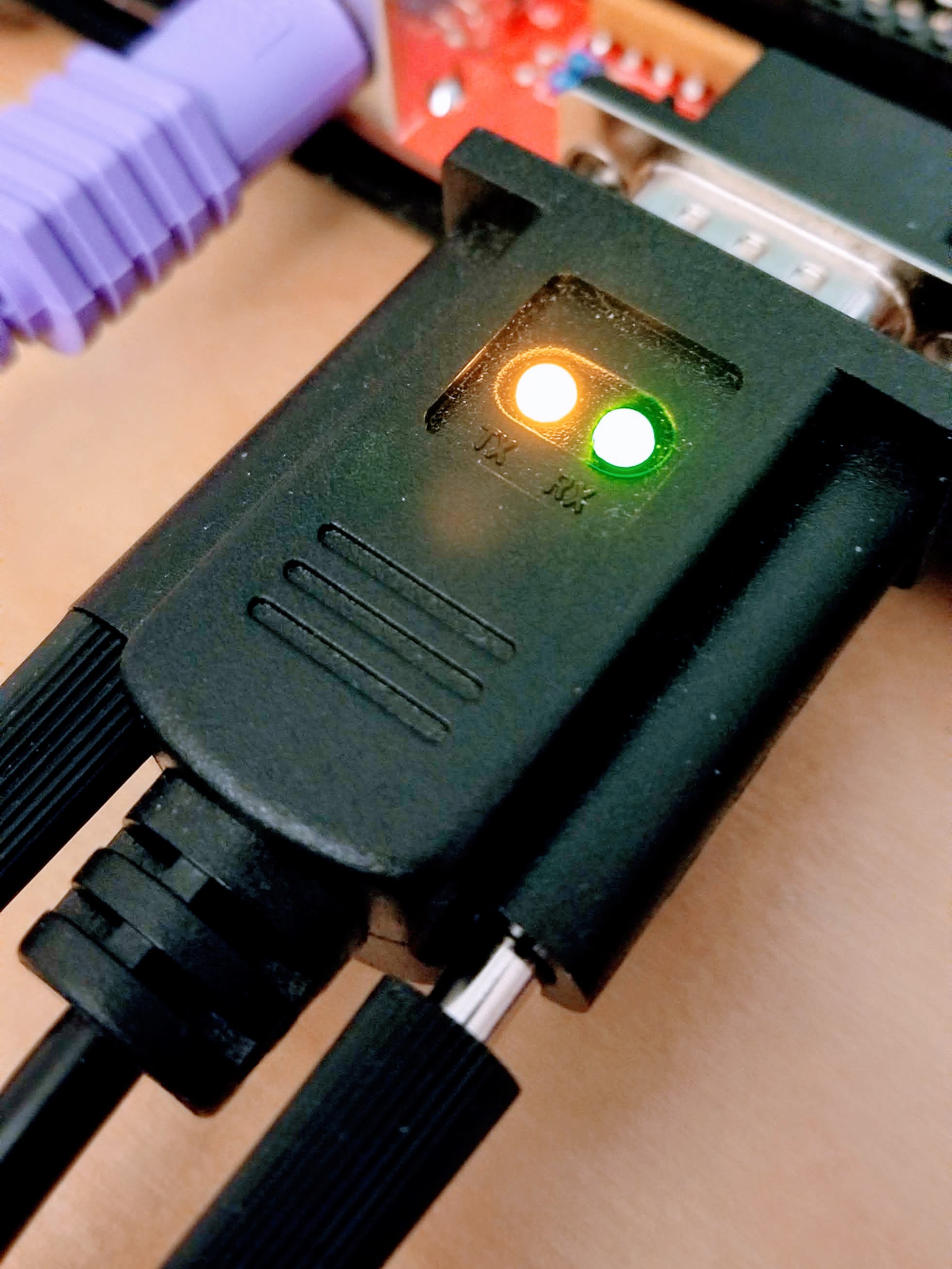
The connection is made via a USB-to-RS232 null-model cable containing an FTDI chip. The cable includes a transmit and receive LED that can be seen below as both lit. This full duplex communication is possible by using two threads to handle both transmit and receive concurrently.
![]()
Each byte typed on the keyboard or received over the serial link is echoed back over the serial connection. The terminal program shown below is displaying the same text being transmitted after it is echoed back.
![]()
This was not a serious attempt to build a functional terminal program, but just a convienient way of testing the keyboard and serial interfaces. Next up is the virtual CPU testing, which should be a lot easier with a keyboard and a way to transfer code to/from the machine.
-
Bit Banged
11/22/2020 at 18:01 • 0 commentsJust completed testing of the new serial receive code and confirmed it can remain synchronized with inputs from 9300 and 9800 baud. It look about two weeks to figure out the new algorithm and code it. The best part was the final solution required no more resources that the overly-simple original. Like the transmit, the receive thread only consumes one virtual machine cycle per bit and only needed one additional (repurposed) unary function.
The diagram below is a little complex to explain in detail here, but might be of interest in showing some of the analysis behind the algorithm.
![]()
The problem being solved here is the synchronization between the transmitter and receiver. Sure, they both run at "9600 baud", but the reality is the clocks are going to drift. This results is the clock slipping one bit ahead or behind periodically. The sampling point also needs adjustment to keep away from the clock edge and prevent spurious data caused by jitter.
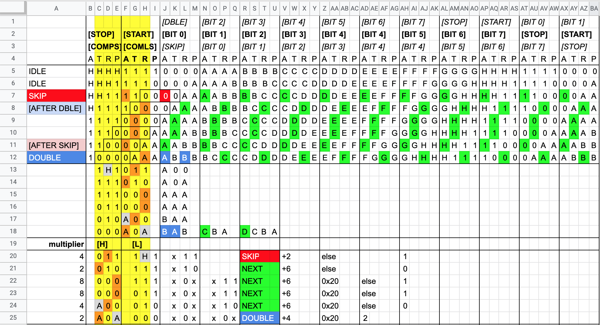
The new algorithm examines six sample points over two bit periods. The two bits in question are the stop then start bit. This is guaranteed to be a high-to-low transition regardless of the data being received. The position of this transition is monitored and the data bit sample point is adjusted to avoid any clock jitter/slippage. In addition, the timing is also adjusted when the transition gets too close to either edge of the sampling window.
The state machine has a 10-bit cycle to match the start, the 8 data, and stop bits. If the clock drifts too far then one cycle is either added or removed. If the sample position has moved such that the next data bit sample would align wtih the start bit then an additional empty skip bit is added. This ignores the start bit and creates an 11-bit cycle to realign the timing of the next 10-bit cycle correctly.
A similar thing is done for the other direction when an additional double cycle is added. This cycle samples two bits in the one cycle and then jump ahead by two bits. The result is a 9-bit cycle and a timing adjustment in the other direction.
These adjustments can compensate for a slip of up to one sample period per byte. The serial ports are sampled on every line, so either 4 or 5 lines per bit, or 40 or 50 lines per byte. This translates to an error of 2.5% (1/40) or 2% (1/50) and provides a window of 9400-9800 baud for the serial connection.
-
TV Typewriter
11/14/2020 at 19:24 • 0 commentsTesting moved to the serial interfaces last month with the development of a simple terminal program. This will display text typed on the keyboard and echo it over the RS232 interface. The serial interface is full-duplex, so data sent back over the RS232 interface is displayed on the screen.
![]()
The first step was to get to a TV Typewriter. The PS/2 interface clock and data bits are sampled during the horizontal sync period. This then drives a state machine that deserializes the data to recover the scan code. Each scan code is added to a buffer and then decoded via another state machine to track things like shift/control key state. Special combinations of ctrl-alt are mapped to system calls with ctrl-alt-del calling the system restart.
The keyboard buffer is sampled by the serial terminal code and any new characters are displayed on the screen and echoed over RS232 at ~9600 baud. There are no plans to develop this terminal code beyond a testing tool, so the terminal only handles lower/upper case characters, carriage return/line feed, and backspace.
The transmit code is working fine, but there was a major design flaw in the receive code. I identified and solved part of the problem with the asynchronous clock recovery but missed the bigger picture with the clock slipping over process cycles. This results in an extra bit arriving in some cycles, or conversely no bits arriving. The Novasaur samples the RS232 data at 9593 baud and will typically miss 7 bits per second if the data is transmitted at exactly 9600 baud. Missing a single bit pushes the stop/start bits out of alignment and the data turns to garbage.
So it's back the drawing board. I have a new algorithm that looks promising, but it is significantly more complex. There are a lot of corner cases that need to be addressed and it will likely take the rest of this month to get to working code.
-
Roll-your-own SID Chip
10/07/2020 at 03:30 • 0 commentsAudio testing is now complete. This includes both hardware updates and the software to generate the sound. Since the sound system is finalized this would be a good point to review all the gory details.
Hardware
To keep the hardware minimal, no registers are dedicated to the audio. Instead time is borrowed from the GPU's glyph (G) register during the horizontal blanking period. The GPU address registers (H and V) are left in tristate during blanking and pulled high to generate the address 0x0FFFF. This is the top byte of the zero page and reserved to store the next audio sample as a 7-bit signed number. The blanking period also switches to the ALU instead of the font ROM with a special audio function at 0x3FFXX. This function remove the sign bit to create a DC-biased audio level and reverses the bits since due to PCB layout constraints the MSB of the audio DAC connects to the LSB of the register.
![]()
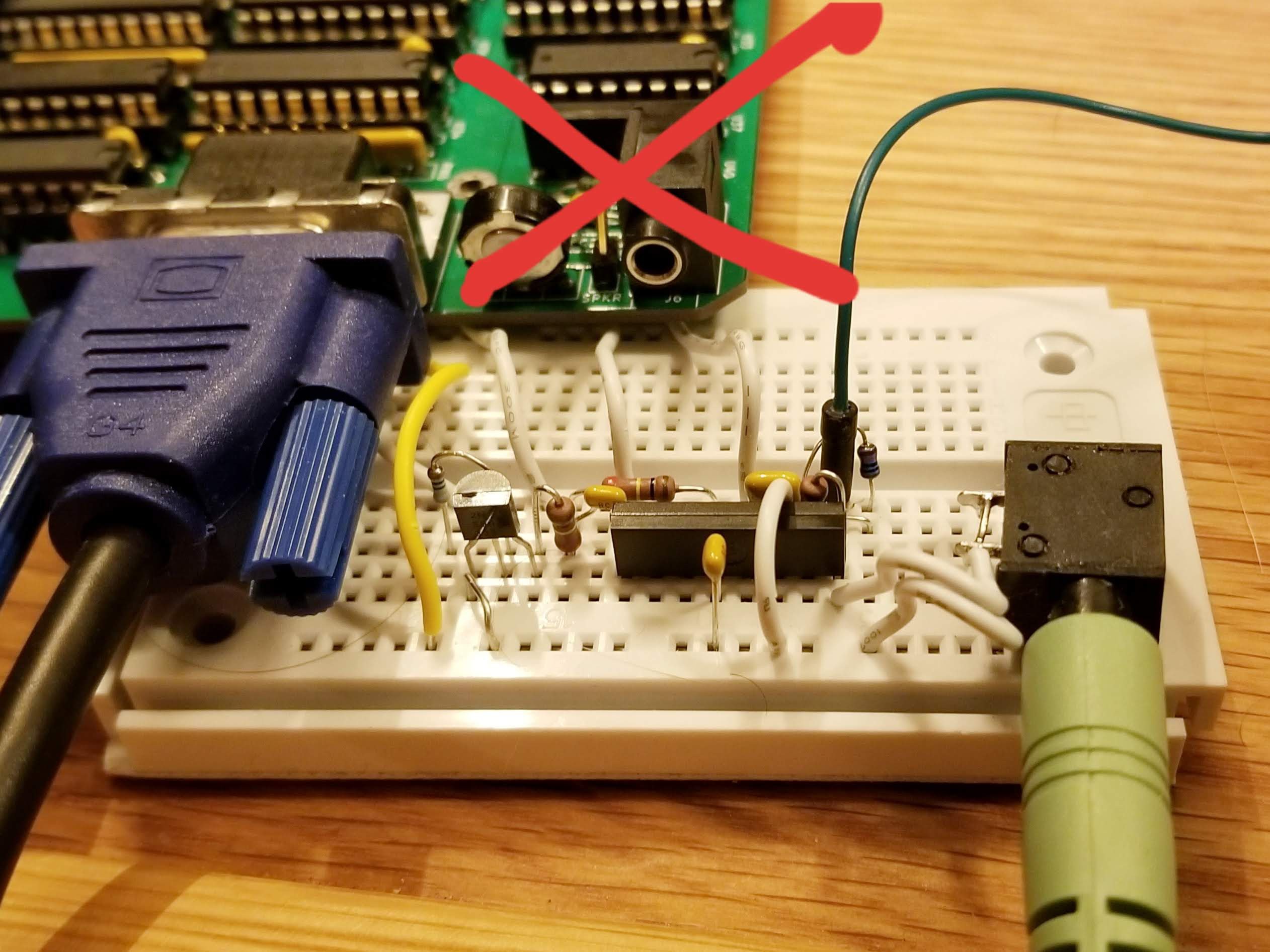
The audio DAC gets the full glyph signal during the active video period and the initial design attempted to use a sample and hold circuit to sample just the audio when blanking. This didn't do a good job of isolating the video signal and led to a lot of noise issues. The circuit was redesigned to the following:
![]()
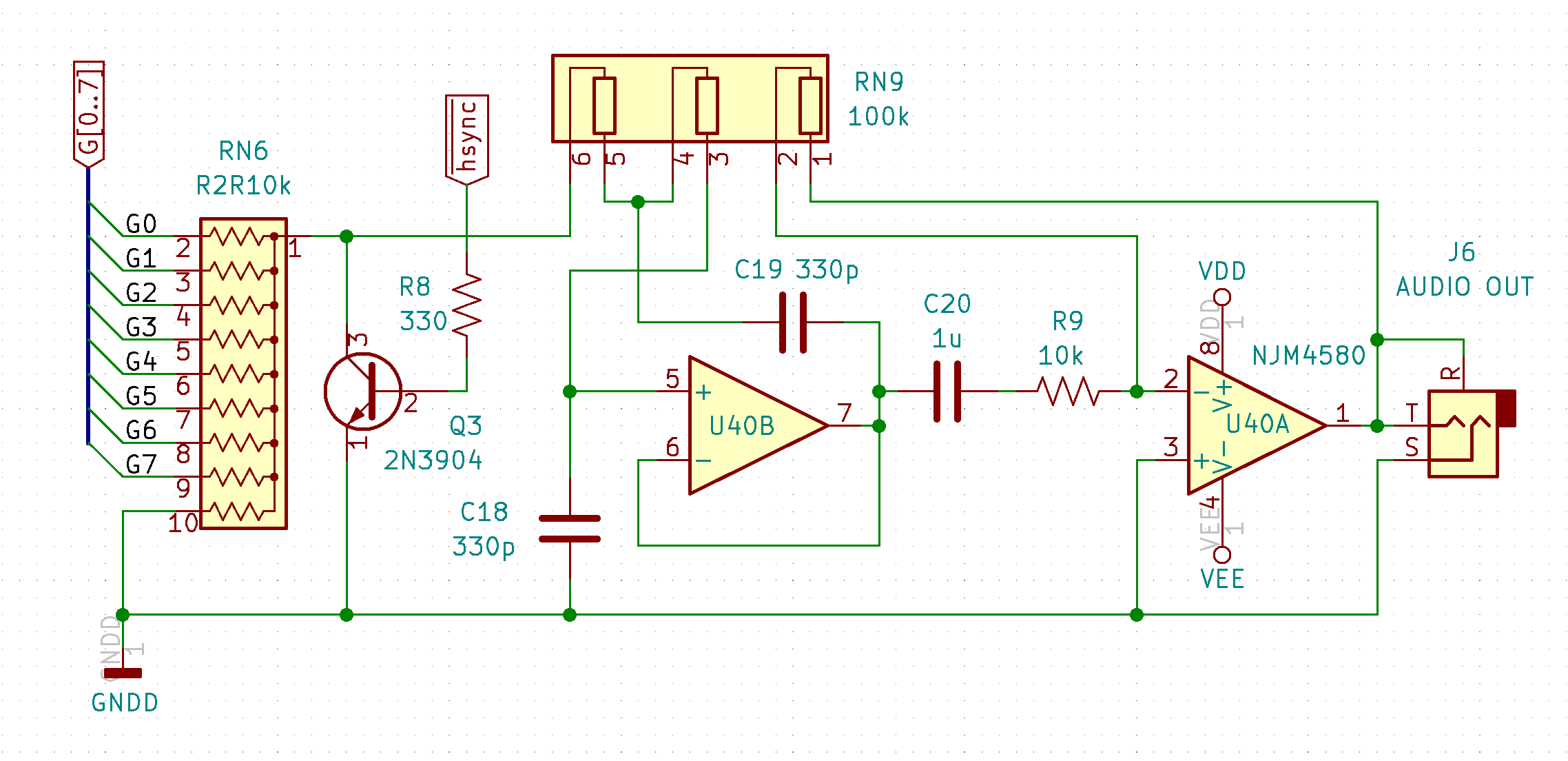
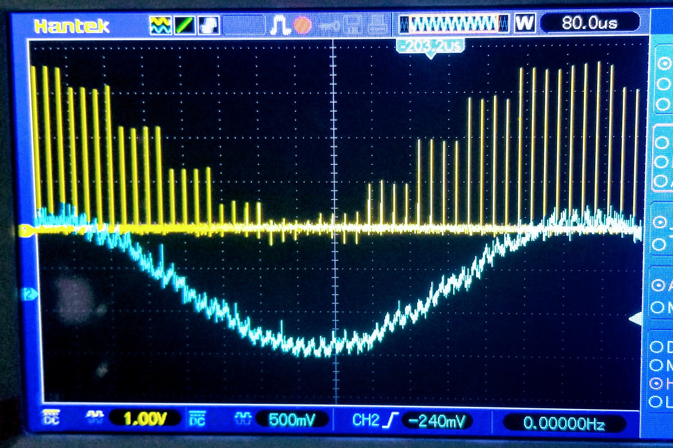
The new design uses the H-sync signal (blue trace below) to mute the DAC during the active period and then allow the audio signal (yellow trace below) to recover during the blanking. This presents pure PCM pulses to the audio filter stage rather than the typical step function. This isn't a problem since they both contain the same frequency domain information. The power level is a lot lower though, so a 20dB inverting amplifier is needed to bring the level up to the -10dBv line level.
![]()
Prior to the amplifier are two filters: A second-order Sallen-Key low-pass filter followed by a passive high-pass filter. The high-pass cuts frequencies below 16Hz and the low-pass above 4.8kHz. This is the Nyquist corner frequency when generating audio at the standard 9.6kHz virtual process rate. The frequency response is shown below:
![]()
Software
The same method used by the Gigatron was shamelessly copied to generate the audio waveform here: A lookup table is used to map each note to a 16-bit value that is then added to a 16-bit counter register. The addition is done at a fixed sample rate such that the register counts to 65,536 at the frequency of the note being played. The upper 8 bits of this counter are then used to index another lookup table that contains a sample of a waveform. Multiple voices are generated by using additional 16-bit counters for different notes and adding the result of waveform lookups together.
Two functions are included in the ALU to lookup the note by the MIDI value and return the high and low byte to use for the 16-bit counter register. The table goes from 0 to 127 for use with the non 60Hz VGA video mode, where full 88-key piano keyboard goes from 21 to 108. For 60Hz VGA the sample frequency is slightly different, so the table is duplicated for this frequency between 128 and 255. In both cases the entire 88-key piano frequency range can be played.
Voices
The Gigatron is able to compute one voice per line during the horizontal sync period. The Novasaur requires up to 48 compute cycles to calculate each voice, which is longer than the entire virtual machine cycle containing the horizontal sync. The audio has to therefore consume additional machine cycles and is treated as an optional feature with the number of voices made configurable.
The audio is handled by a non-blocking thread scheduled at the end of the first line in the virtual process cycle. At least 2 virtual machine cycles are required if the audio is enabled and this can be extended by an additional cycle per voice up to a total of 4 cycles. The first two cycles provides the first melodic voice and an additional non-melodic voice that would typically generate a random noise signal. Each additional cycle adds a voice for up to 3 melodic voices in the VGA and SVGA video modes, or 2 voices in the XGA mode.
The non-melodic voice uses the process line counter of the video display instead of a dedicated 16-bit counter register used to control the frequency. The result is a cycle frequency that matches the 60 or 75Hz frame rate of the video. The noise sample would contain all frequency harmonics across the audio range, but this repeats every frame for a significant 60 or 75Hz harmonic. This can be mitigated by using two patterns that alternate based on the sign of the audio signal at the end of the frame. This still causes issues if only that noise signal is being generated, but mixing one or more melodic voice will modulate the selection between the two noise patterns.
All the voices are calculated on the same line. The result of each voice calculation is a signed number that is summed to determine the final value of the audio sample. This sample is then output on every line until the thread runs again on the next process cycle. Even though the resulting PCM pulse is output at the horizontal line frequency the value only changes at the process frequency shown below:
Video Mode Horizontal Frequency Pulses per Cycle Cycle Frequency Nyqust Frequency VGA 60 31.5kHz 3 10.5kHz 5.25kHz VGA 75/SVGA 38.4kHz 4 9.6kHz 4.8kHz XGA 48kHz 5 9.6kHz 4.8kHz Waveforms
There are three waveforms available for the melodic voices: sine, square, or sawtooth. These waveforms are stored in a wave table consisting of 16 entries. The sine wave takes up one entry and the noise patterns take up two. This leaves 13 entires for the other two waveforms, with 6 entries for the square wave and 7 for the sawtooth. But why so many?
The square and sawtooth waveforms are very rich in harmonics: The sawtooth consists of every harmonic with a second harmonic at 1/2 the amplitude, the third at 1/3, the fourth at 1/4, etc. The square wave is similar, but contains only the odd harmonics. The issue arrises when you consider what happens to these harmonics with the relatively low Nyquist corner frequency of 4.8kHz. As an example, if one of these waveforms is generated at 1kHz then there will be alias distortion at the 5th harmonic and above. The 5th harmonic is only -14bB below the fundamental, the 6th is -15.5dB, the 7th is -17dB, etc. These are still quite significant amplitudes and quite noticeable on the Gigatron with a Nyquist corner frequency of only 3.9kHz.
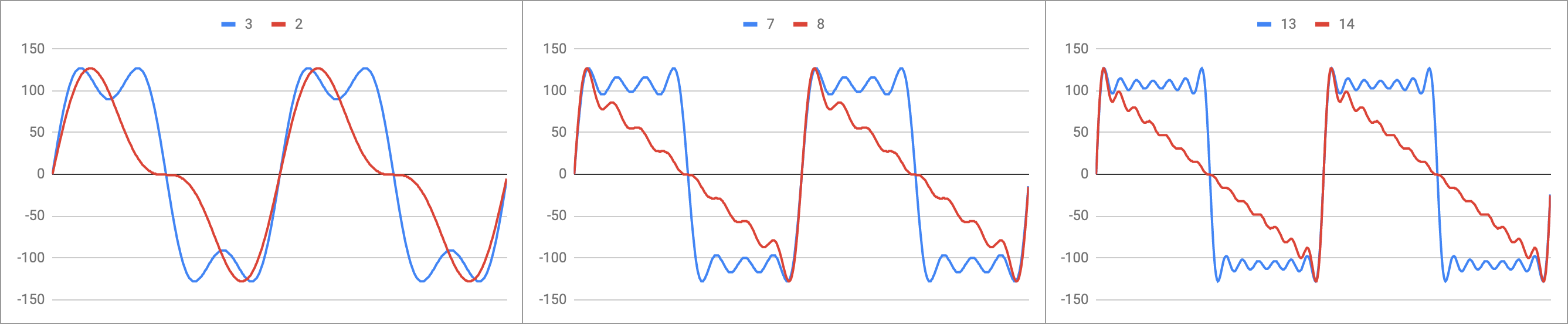
The solution is to band limit the waveforms. Any note below 2.4kHz will not be able to reproduce any harmonics, so only the sine wave would be selected at these frequencies. Below 2.4kHz the harmonics can be added one at a time to produce a progressively richer band-limited version of each waveform. The diagram below shows the actual wavetable data for the sawtooth (in red) and square (in blue) waveforms. The first example shows two cycles of the 2nd and 3rd harmonic versions, the next is up to the 7th and 8th harmonics, and the final example is the highest harmonic version in the table with up to the 13th and 14th harmonics:
![]()
The next table shows the makeup of the wave table. The first column is for entry 0 and 1, where entry 0 is the fundamental (sine wave) and entry 1 is the fundamental plus the -6dB second harmonic (red line in left panel above). The next column is for entry 2 and 3, where entry 2 is the fundamental plus the -9dB third harmonic (blue line in left panel above). The last column are the two noise patterns. Each row progressively adds the harmonics, where the first row contains the sine wave and odd harmonics (square waves) and the second row contains all harmonics (sawtooth waves).
0,1 2,3 4,5 6,7 8,9 10,11 12,13 14,15 Square 1 +3 +5 +7 +9 +11 +13 noise0 Sawtooth +2 +4 +6 +8 +10 +12 +14 noise1 An additional ALU function is used to find the table entry given the note where the highest harmonic will be below the Nyquist corner frequency and avoid aliasing. The least significant bit can be set to 0 to select the square wave, or 1 to select the sawtooth. This function is not needed to select the sine wave since you would simply select entry zero regardless of the note's frequency (Note: no entries exist for frequencies above the Nyquist corner frequency).
Attenuation
The waveforms are stored in the lower portion of the WAV ALU binary operation. This operation can be used in the single-cycle context and will return the value of the waveform as a 7-bit signed integer (-128 to +127). The WAV operation is a two-cycle operation however, where the second part of the function contains an attenuator to reduces the amplitude of the waveform during the second cycle.
The lowest attenuation is 12dB, or 1/4 of the sample value. The waveform has to be divided by at least 4 since up to 4 waveforms could be summed to create the final audio sample. This lowest attenuation has a value of 15 and then the amount of attenuation is increased by 1.5dB for each step going down to 1 for an attenuation of 33dB. A value of 0 represents full attenuation and the sample is muted to always return zero.
ADSR
Controlling the attenuation is useful for controlling the balance of each voice, but its primary goal is to control the envelope of the audio waveform. This is achieved by adding a set of envelope controls to each voice for the attack, decay, sustain, and release of the amplitude. The sustain is also used to gate the voice, so setting the sustain to a level above zero will cause the voice to attack to maximum volume and then decay to that sustain level. The sustain can then be dropped to zero to cause the voice to release to the muted state.
The resource consumption for the envelope control is relatively low: If the audio is enabled then each voice is updated sequentially at the end of the video frame with all voices updated at a rate of 15 times per second. The update involves increasing or decreasing the attenuation from 1 to 15 steps at a time. The fastest change would be 15 steps in 66ms, so turning the audio completely on and then completely off in 133ms (kind of slow). The slowest change would be 1 step per 66ms, so turning the audio completely on or off over a 1 second period.
The keyboard scan is also controlled at the end of the frame, so for 60Hz frame rates there are only 3 slots to control the envelope. In this case the third melodic voice would not get ADSR control, but can still be controlled manually if needed. Only the 75Hz video mode would provide all 4 voices with ADSR.
Video Mode Max Melodic
VoicesMax Voices
w/NoiseADSR
VoicesVGA 60 3 4 3 VGA 75 3 4 4 SVGA 3 4 3 XGA 2 3 3 The algorithm utilizes an indirect addressing method to store a reference in the delta register. This would start by pointing to the attack register, which in turn would store the number of steps to add per 66ms each cycle. This positive number is added to the current level of the voice and checked to see if it has overflowed. If it has overflowed then the volume is set to the maximum and the delta is changed to reference the decay register. The decay is a negative number so the volume will start to decrease on the next cycles. The same overflow check is done for the zero crossing, but also a checked against the sustain level. If either is met then the level is set to the sustain and the the delta is set to zero. This indicates that there is no indirection for the delta and just to check if the sustain level has changed.
To gate off the voice off, the sustain level is dropped. This will cause the delta to be updated to reference the release register, which like the decay also contains a negative value. This results in the level dropping to the sustain level again, which would typically be zero. To restart the cycle the sustain level is increased triggering an update to the delta to reference the attack register again.
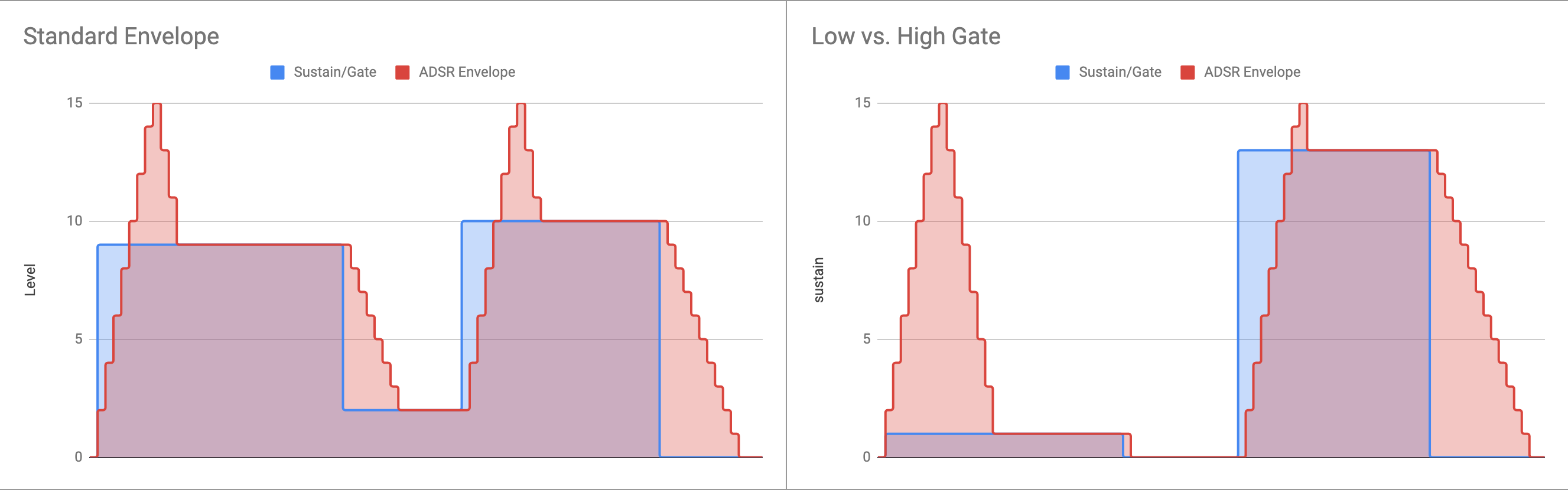
The examples below shows the effect of changing the sustain level and the resulting envelopes. The left example shows the cycle without dropping to zero between two notes. On the right is a low gate used to cause a short note and a high gate to cause a longer note.
![]()
One final feature is the ability to control the value of the wave harmonics using the envelope. The deltas are stored as 7-bit numbers where the lower 3 bits would normally be left as zeros. If they are not zero then the value of the wave table entry will be updated along with the amplitude. This acts like a voltage-controlled filter being controlled by the envelope and adjusts the harmonic content of the wave to add more texture to the note. The attack/decay deltas have to be symmetrical though. If the wave table doesn't arrive back at the starting point then it will drift over the noise entry and cause a nasty mess!
-
Lo-Fi
09/20/2020 at 22:01 • 0 commentsAfter video came the audio testing. There was a known issue with a nasty 60Hz buzz breaking through in the audio channel. The last value in the glyph register shows up in the audio channel when the blanking period starts. This was assumed to be the cause of the buzz and the correct blanking during the front porch should take care of it. It turned out there was more to the issue than this...
The audio DAC gets the full video signal during the active part of the video line. A sample and hold circuit is used to sample only the audio level during the horizontal blanking. However, there appears to be a significant parasitic capacitance associated with the DAC. This capacitance is charged up during the active video and then takes significantly longer than the front porch time to discharge. The result is an echo of the video signal in the audio channel, resulting in a periodic waveform at the frame rate of 60Hz.
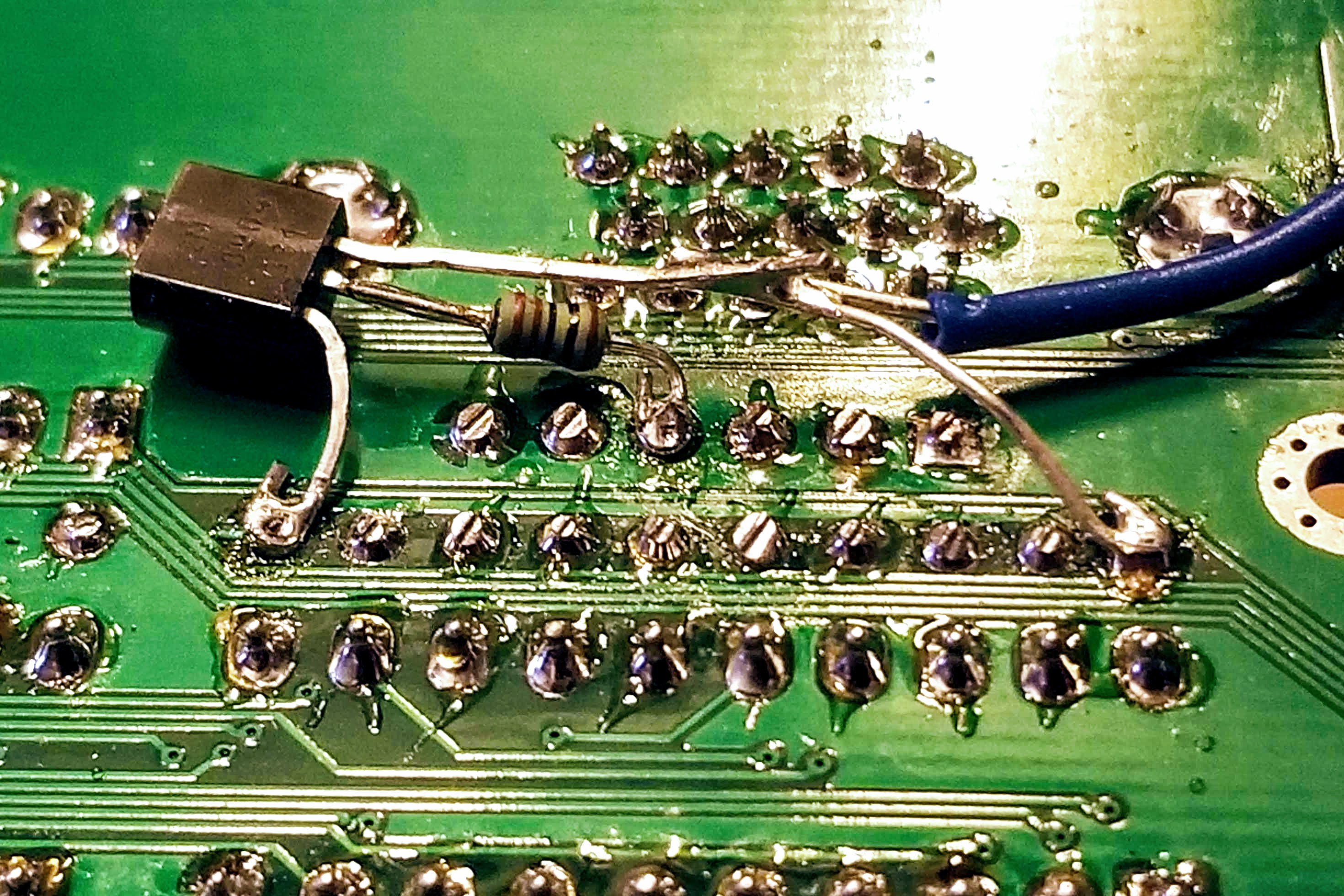
The solution was to add a muting circuit to the DAC. This is just a transistor that shorts the output of the DAC to ground during the active video.
![]()
This worked so well that the sample and hold circuit was removed. The DAC now feeds the raw PCM pulses directly to the second-order low-pass filter section. The filter will need to be redesigned slightly to help filter out the increased high frequency harmonics and amplify the lower RMS level of the PCM signal. The following shows the current output of the DAC for an 880Hz sine wave:
![]()
Note that the pulses come in groups of 4. The audio value is calculated once per virtual process cycle, but output once per line. The SVGA timing shown here has 4 lines per process cycle. The output wave (shown in blue) is via the existing filter design.
-
Classic VGA
09/14/2020 at 04:19 • 0 commentsThere was a completed version of the video system running a few months ago. Pretty much everything changed during the main software development and that also included the video modes. One change was to add the classic 60Hz VGA mode and allow even the ancient plasma TV rescued last year to understand the video timing.
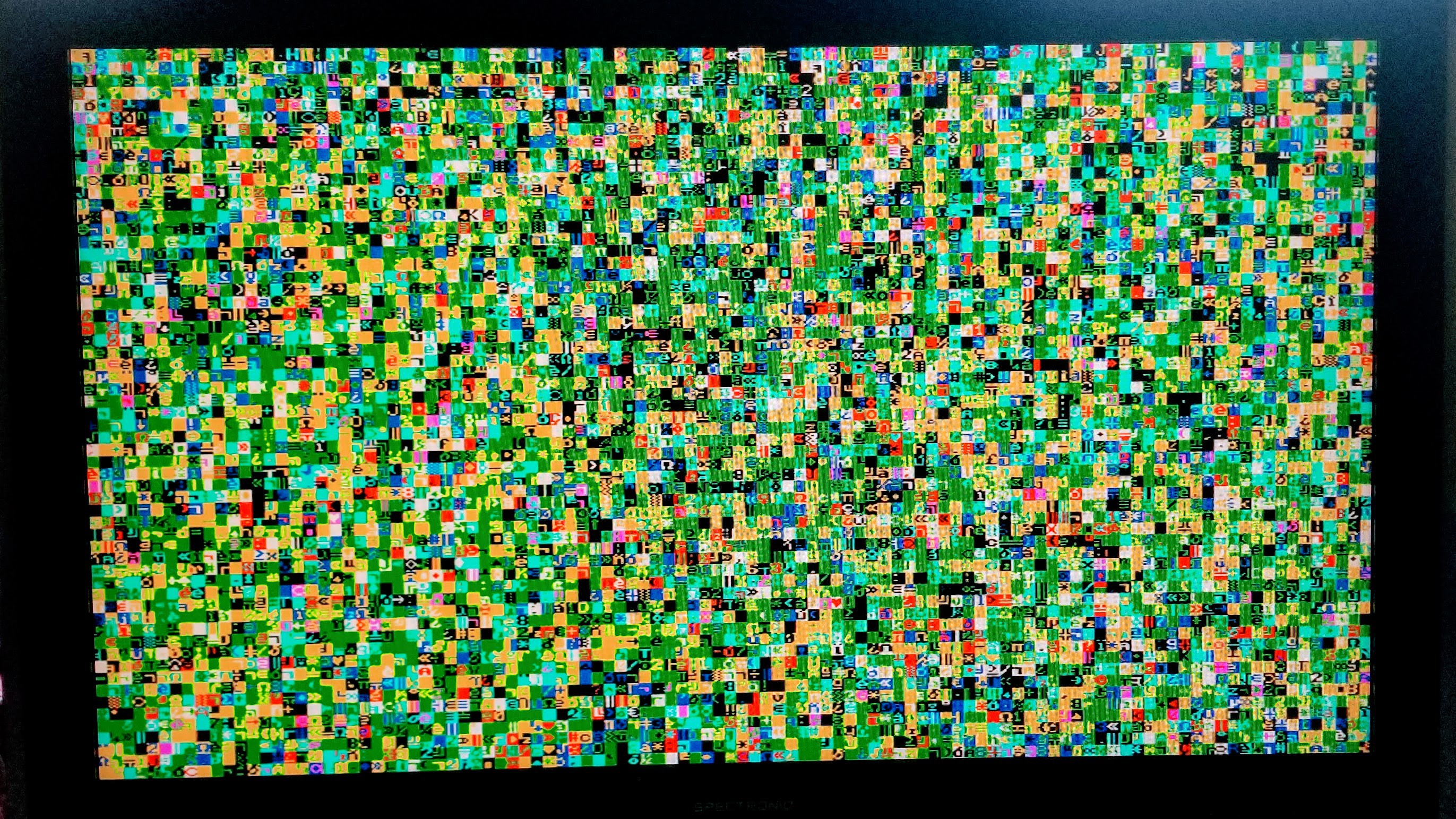
![]()
The image above shows the old TV displaying 104x60 of random text. This 104 column text is due to the dot clock being 33MHz, or 30% faster that the standard 25MHz VGA clock. This results in an additional 24 characters of text being output per line.
So how is the classic VGA timing done?
The original video modes used a process cycle of 4 lines of 5 virtual machine cycles. The virtual machine runs at 192kHz, so the horizontal frequency is 38.4kHz and close enough to support 75Hz VGA and 60Hz SVGA modes.
The process cycle can be reconfigured to 5 lines of 4 virtual machine cycles. This results in the same block of 20 cycles and the serial compatible process cycle frequency of 9.6kHz. The horizontal frequency is now 48kHz and close enough to support 768-line video modes such as XGA.
The new 60Hz VGA mode uses a configuration of 3 lines of 6 virtual machine cycles. There are some issues with this though. The process block is now 18 cycles and the process cycle frequency does not support a standard UART frequency, so not serial support. The horizontal frequency is also little high at 32kHz, but this can be fixed by adding a short delay to each line.
The 60Hz VGA timing is determined by reseting the horizontal line every 262 cycles. The 6 virtual machine cycles add up to 258 (6 x 43), so an additional delay page is added before the horizontal sync page. The delay burns an additional 4 cycles to result in a horizontal frequency of 31.48855kHz (8.25MHz / 262). This is very close to the exact VGA horizontal frequency of 31.46875kHz.
The frame is made up of 175 process cycles consisting of 3 lines each. This results in the exact 525 lines of the standard VGA mode and a vertical frequency of 59.98Hz. Again, this is very close to the VGA/NTSC standard of 59.94Hz.
-
Coding Complete
08/30/2020 at 01:18 • 0 commentsComplete doesn't mean finished though! This was not like a modern iterative development process with small incremental changes as features were added and enhanced. The entire system had to be coded before all the dependancies were resolved. This took an entire year and there are still several weeks of testing ahead (and some inevitable updates).
So what has been coded? Essentially the only program that will ever be written to run on this hardware. This is the firmware that forms the hardware abstract layer that all other programs will use to access the functions of the machine.
There are two reasons for this approach. The first (and least significant) is the limited implementation of the Harvard Architecture: The system uses only one ROM and one RAM chip and there are two data data paths, one for program and other for data. It makes most sense to put the program in the ROM, so this means a new machine code program can not be loaded without reprograming the ROM.
It is easy to add another RAM chip to the system and configure this as an additional bank of program memory. This solves the issue of not being able to load new machine code at run time, but there is a far more significant issue to consider: The main reason for not allowing a user to add their own machine code is to prevent a user's program from taking control of the CPU execution.
If the system yields to a user's program then that program needs to be aware and responsible for all the critical real-time activities required to make the hardware work. The hardware provides the bare minimum to support the electrical interfaces for things like audio, video, and serial communications. The software is responsible for all the timing and state for these interfaces. An interrupt mechanism could be employed, but this is impractical with horizontal video timings running as fast as 48kHz.
The way to keep the system simple is to use a byte code interpreter to execute the user's program. This does have a significant performance impact but there is plenty of room to extend the interpreter with fast native functions for common activities. A big advantage of the interpreter is the ability to provide binary compatibility with an existing processor like the 8080. This makes it easy to port things like CP/M to the platform.
A lot of the firmware features have been discussed in previous logs during their development. A few things have changed as the final pieces came together, so these will be expanded on in later logs. For now this is a quick summary of the final firmware: The base system consists of 120 pages containing over 5,000 assembly instructions (not including 900 NOP instructions to pad timing). This code operates 10 non-blocking threads to control: horizontal video timing, vertical video timing, PS/2 keyboard scan, realtime clock, serial I/O sampling, RS232 transmit, RS232 receive, wavetable synthesizer, maskable interrupts, and byte-code interpreter.
Novasaur CP/M TTL Retrocomputer
Retrocomputer built from TTL logic running CP/M with no CPU or ALU