 Discrete Electronics Guy
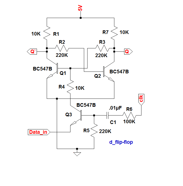 The above circuit diagram shows the D flip-flop. It is a practical one. Here the 2 transistors T1 and T2 are work as latch (previously discussed) and the transistor T3 is used for drive the LED. Otherwise the current drawn by the LED changes the voltages at the output Q. The fourth transistor is used to control the input data. It passes the data only when it's base is at high potential. It's base voltage is generated by the differentiator circuit created by using capacitor and resistors. It convert the input square wave clock signal to sharp spikes. It create the transistor to on at an instant only. This is the working.
The video shows its working and theory.
For more details about its working, Please visit my BLOG, link given below,
https://0creativeengineering0.blogspot.com/2019/03/what-is-d-flip-flop-using-discrete.html
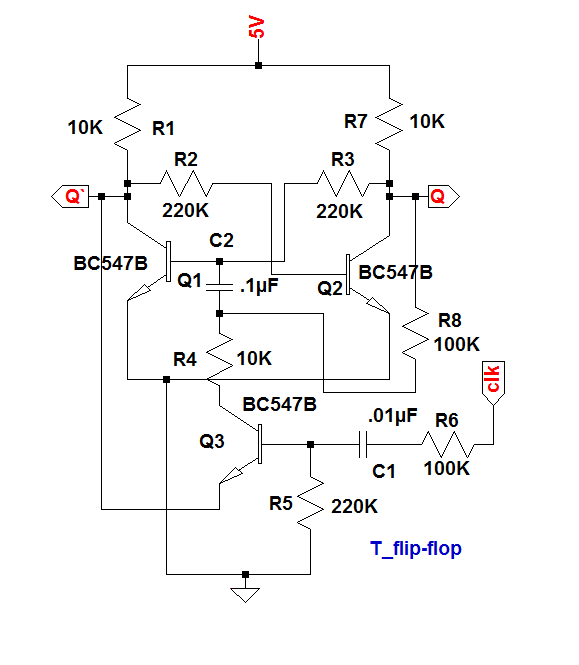
The T flip-flop is made from D flip-flop. For this, connect the data input to the complementary output Q'. So It's output state change automatically (toggles) when clock is applied. The circuit diagram is given above. The circuit contain an extra capacitor and a resistor. The capacitor is used to introduce a lag between the output and input (latch transistor). Otherwise it don't works. Because we connect the transistor output to it's base itself. So don't works. It works only when the two voltages has a time lag. This lag is introduce by this capacitor. This capacitor is discharges by using the resistor from the Q output. Other wise it don't toggles. The Din connected to the complementary output Q' for provide the toggle input signals. So by this process this works very well.
For more details about circuit, please visit my BLOG, link given below,
https://0creativeengineering0.blogspot.com/2019/03/what-is-t-flip-flop-using-discrete.html


 Dylan
Dylan
 Allen Mamaril
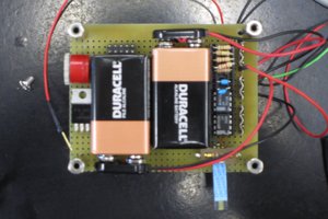
I made it exactly as described with the exact same components, and it works (up to a point). There are, however, timing glitches. I was trying the circuit at a clock speed of 60Hz and a data pulse of 23Hz and found the flip flop triggered correctly most of the time BUT found on the falling edge of the data line within 2.9ms AFTER the clock leading edge trigger, the flip flop triggered. At higher frequencies it got much worse. Making C1 smaller (100pf) seemed to solve the issue at up to 1kHz at least.