 blinkingthing
I've been torn on what features I wanted to include on this add on. I wanted to land someplace between LED's that turn on and a full fledged serial-talking EEPROM-having thing that I don't understand all the way.
I read through the documentation of and played with my badges and add-ons from DC26 trying to find inspiration. I love the ammount of interactivity between the Darknet badge and it's Eggplant SAO and I want to replicate something like it, but alot of what makes it work goes too far over my head so I probably need to tone things down a bit. I also went through the ANDnXOR github and checked out the SAO reference designs they've put up for this coming defcon. I really like the idea of putting in an EEPROM and having some sort of badge/SAO communication/identification but again, these concepts are going over my head and I don't really have the time/patience to read, experiment, fail and eventually learn at the moment.
At the very least I wanted the LEDs to blink in some fashion. I started playing with LED sequencer circuits using a 555 + 4017 IC. While this was an interesting exercise, figuring out the animations I wanted wasn't going to work with this circuit.
My other option would be a microcontroller. I decided (without much research) on an attiny85. It was a really good experience learning how to put arduino code on the attiny, something I had never done before. Using the micro I am much more satisfied with the control I have over the LED animation. I also now have an opportunity to try and utilize an input signal coming from the badge over one of the new pins that came along with the new SAO standard.
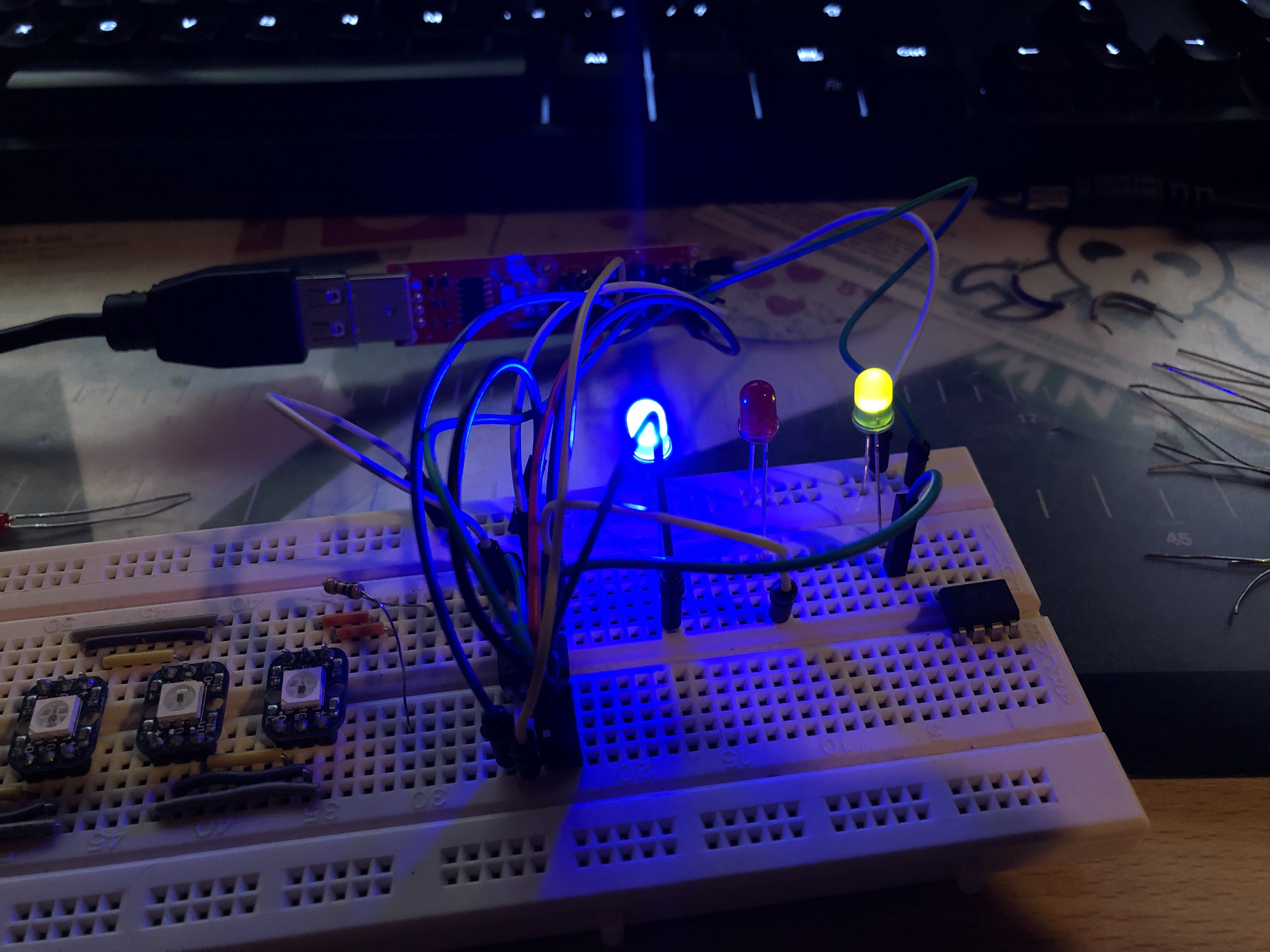
I got a working breadboard circuit going before re-desigining the PCB. I can reprogram the attiny85 so long as it's not connected to the rest circuit, so my plan is to finalize the code and flash the chips before soldering them to the board, at least for the next prototype. I'll look into having PCBWay program the chips and assemble them for the final batch, but I'm already curious if I have enough lead time to that kind of thing. I guess we'll find out.
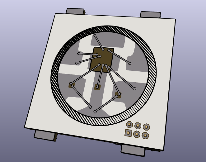
After semi-settling on a circuit I went back through and redesigned the graphics for the PCB in Inkscape, svg2shenzen'd them again and put everything in KiCad. Between the last design and this one I've decided to swap out components. I'm swapping the 1206 leds for some OSRAM reverse mount PLCC2 LEDs. These are a bit bigger and hopefully easier to solder. Same with the resistors, I'm switching from 0805 to 1206 to try and make it a little easier to solder. This required switching out the footprints I had been using.
I put a little bit of effort into labeling things and making sure they were legible even with all the line art I have going on on the back of the board. This required a bunch of back and forths between KiCad and Inkscape to get everything just write. Huge shout out to MrTwinkleTwinkie as his youtube SAO streams made this a lot easier to wrap my head around. At one point I caught a mistake in my back masking in the 3d viewer, I didn't leave a gap in the mask to let the light through the back of the board! Another thing I did, not sure if it's a mistake or not, was to remove the silkscreen circle that was noting the VCC pin on the SAO header. It was interfering with the artwork on the front of the board so I just removed the offending circle from the connector's footprint in KiCad. This may be a no-no, but I'm not sure.
That's where I'm at now. Just submitted these designs to PCBWay. Now I wait...
Discussions
Become a Hackaday.io Member
Create an account to leave a comment. Already have an account? Log In.