 blinkingthing
Rev 2
The 2nd version of the shitty pixel SAO boards showed up yesterday and I was eager to get components on them. This revision has dramatically altered artwork, more along the lines with what I originally envisioned. I inverted the black and white, edited some copper areas to reflect the shiny silver parts of a WS2812 and left the area that represents the IC controller for the WS2812 unfilled to potentially let more light from the LEDs show through the front. I was hoping that this area would take on the color of the combined light from the 3 different LEDs.
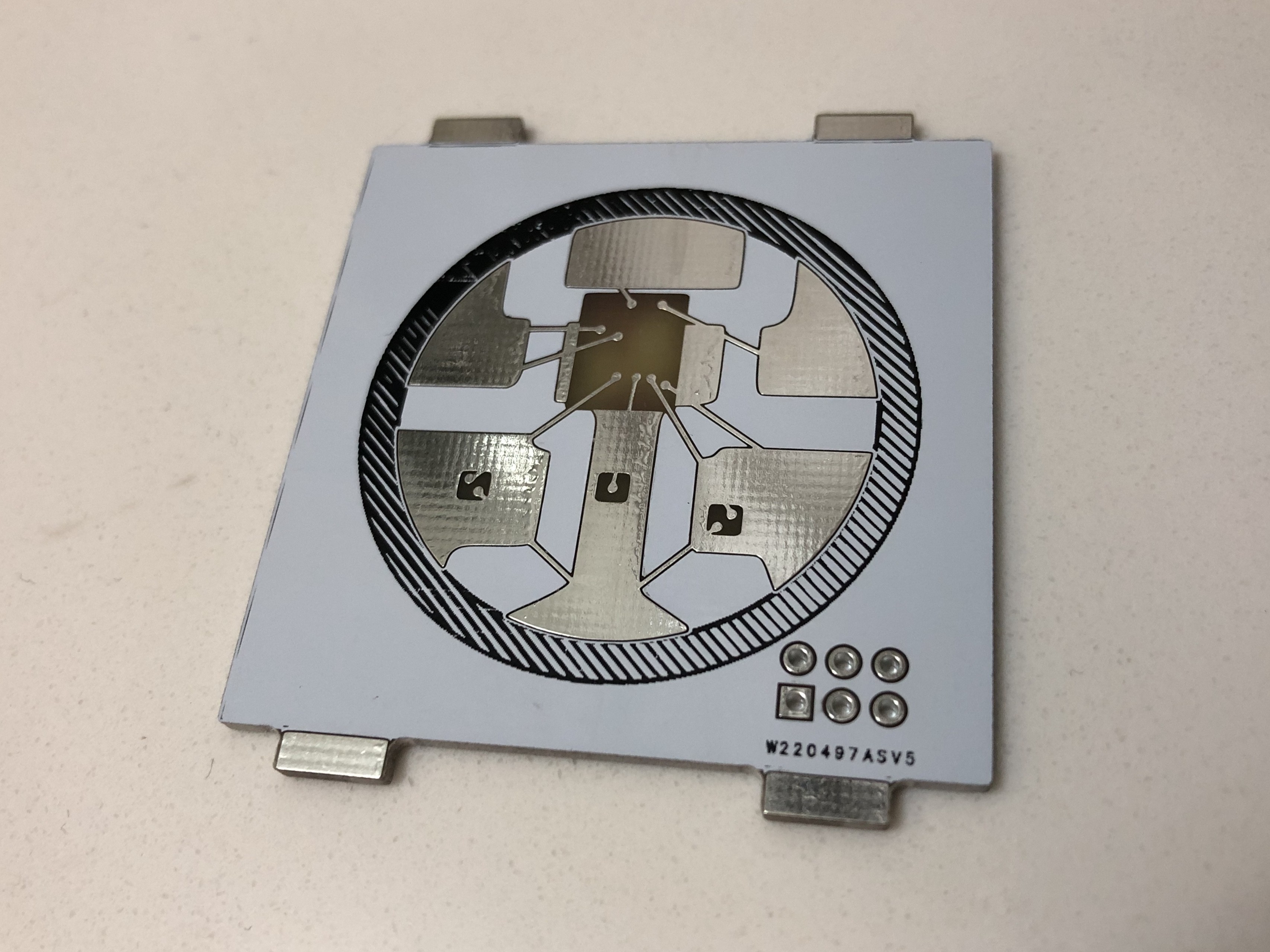
I decided to switch from 1206 led's to a reverse mount gull wing PLCC2 package LED. I used some Osram TOPLED and some from SunLED as I couldn't find all the colors I want in the Osram TOPLED brand from digikey. This required that I make a custom footprint. I got the required specs for the different LEDs I chose from the datasheet on the product's digikey page and decided on dimensions for the footprint that would accommodate both the Osram and SunLED brand led's.
I also moved the SAO connector towards the center of the board slightly so that it wouldn't overhang past the edges of PCB, an error I made on Rev 1 where I wasn't using the SAO connector footprint but instead was using a generic 02x03 pin header footprint.

Now it's Smart
Another big addition to this board was the attiny85. I desperately wanted some more functionality from this add on, mainly the ability to blink. Otherwise my handle would be put to shame. An attiny microcontroller seemed like the way to go based on my severely limited knowledge and experience. I liked the idea of being able to use the Arduino IDE to write the software as that's something I'm fairly familiar with.
I looked to the Darknet Eggplant SAO to help guide this design. That board was designed with pads to allow for in-circuit programming of the microcontroller. I briefly read through some documentation on how to design a circuit that would be compatible with in-circuit programming, but didn't get the ideas fully fleshed out and decided to forgo this for this rev of the board. This lead to me mangling the first SMD attiny85 I tried to hook up with IC hooks to my AVR programmer.

Too Many Hooks in the Kitchen
I remember thinking about this step in the process while I was designing the PCB's thinking that it wouldn't be too much of a hassle. Turns out it kind of is. The process of soldering the chip to the board, hooking it up, and programming it will take me way too long if I want to create any number of these. I want to go down the in-circuit programming route as it will allow me to fix anything that comes up post-production, plus the end user could hack away at it if it had it's programming pins exposed.

Assembled by Hand
After programming the attiny, I went ahead and put the rest of the components on the board and it actually fired up as expected. I used 0805 resistors even though this board is designed to use 1206 size, I just didn't have time to order them and wanted to see if I could make it work with the 805's. I think I'm going to reposition R1 so it's not so close to the SAO connector for the version. I also want to leave a blank spot on the back for the board manufacturer to print their inventory number (I assume it ended up on the front this time because I didn't leave them any room on the back.)
I'm curious if I'm going to go down the road of having the PCB manufacturer place and solder the components for me all in one go. I still have to weigh out my options.
RGB
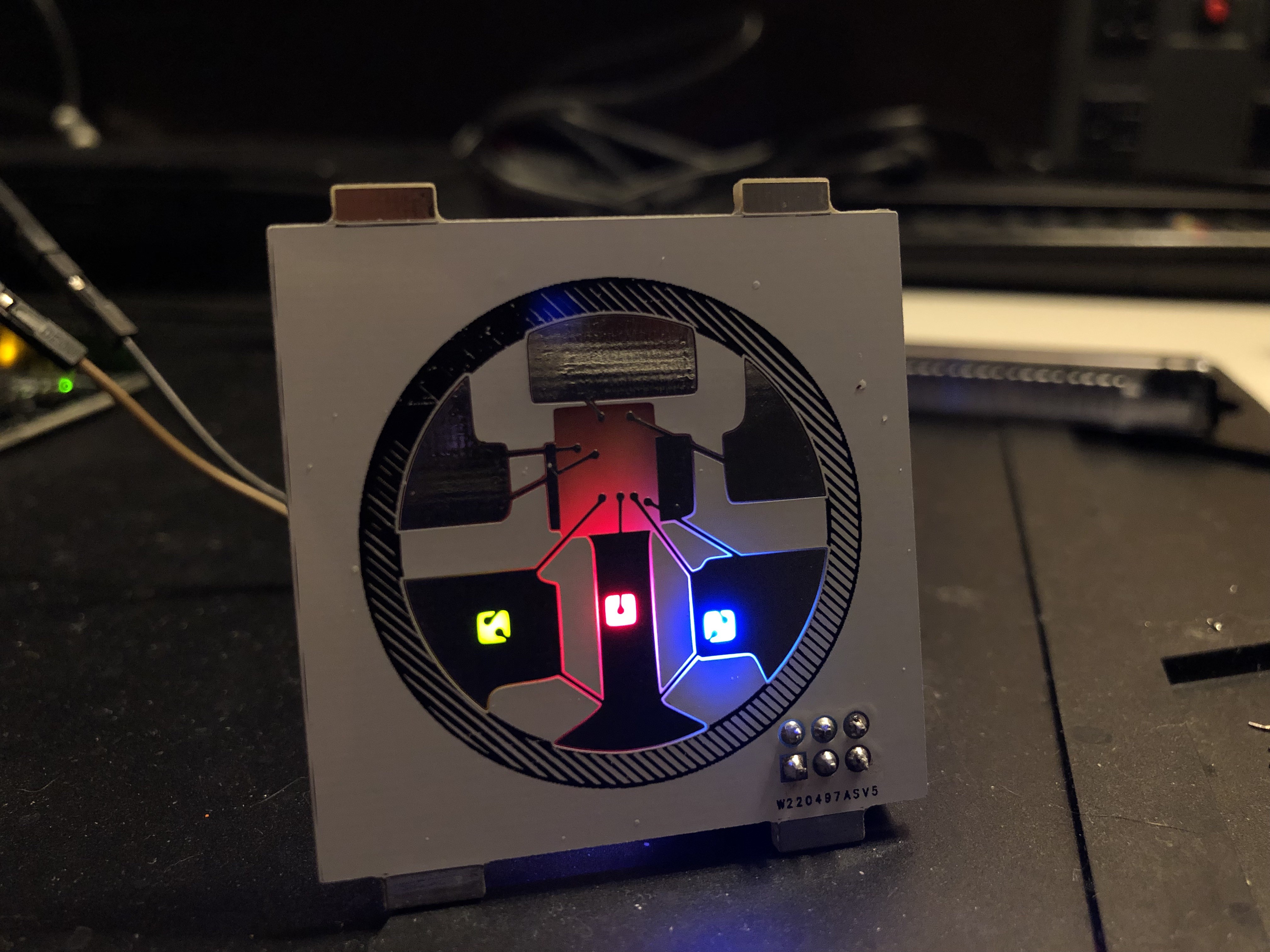
With the altered artwork, light shines through the board slightly differently than the previous version. The small squares are illuminated solidly as well as the areas beside the bond wires. I really like the way the light sort of looks like it's drawn up the bond wires via capillary action and mix in the center where the controller for the WS2812 would be.
It Blinks!
The animation I had worked out on my breadboard setup worked for the most part. The one issue is that the timing of everything seems MUCH slower than when I was using an Arduino or even the through hole version of the Attiny85 that I was breadboarding with. I am guessing that this is because I forgot the 'burn bootloader' step to set the fuses on my attiny before programming. I haven't soldered together a second prototype yet but I'll be sure to try that and make sure that things are running with the proper timing before deciding that this is an issue.
What's next?
- Slight alteration of art to reduce size of copper circle on the front of the SAO.
- Possibly switching SAO connector for an SMD version to clean up the look of the SAO design.
- Figure out how I'm going to program the attiny85's at scale.
- Learn how to design a circuit with an in-circuit ISP programming header. (Even if I don't use it for this SAO)
- Solidify the Arduino code / software.
Discussions
Become a Hackaday.io Member
Create an account to leave a comment. Already have an account? Log In.