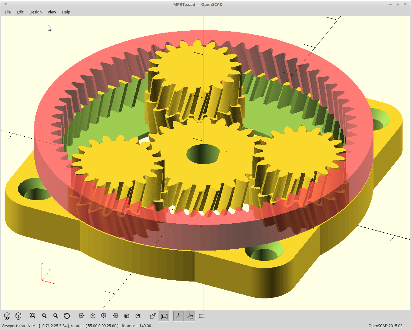
Finally got around to generating a version where the input and output gear pitch matches the corresponding layers, aka split planets. Here it is, with a twist.

I generated the above with zero backlash allowance, just to make sure all the teeth were meshing appropriately.
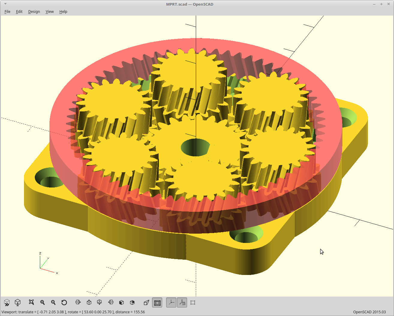
It works with 6 planets as well.

I think that may be a bit much though.
I'm still missing the calculation for one number, and so the code contains a fudge factor I need to eliminate yet before it's fully parametric and gets uploaded.
Now to add this to the #FilaMecanum project..
 Daren Schwenke
Discussions
Become a Hackaday.io Member
Create an account to leave a comment. Already have an account? Log In.
Note that having an independent sun gear that turns to its own accord does not really help with tilting planets. Yes, it presses the teeth into the upper ring gear and prevents them from tilting out of mesh. But the main forces are tilting the planets sideways along the circumference. So having a sun gear spanning both side of the planets it holds the top and the bottom of the planet at the same place. But if the upper sun is able to move separately only the length of the teeth keep the planets from tilting. When I tried that a while back it was not enough.
Although it may sound counter intuitive a gear box with a planet carrier is probably easier to start with and optimizing the planet carrier away is may be better left as a later step.
Are you sure? yes | no
Good points.
I think if I was keeping the planets as large and flat that a single raised ring printed into the top/bottom surface they would rotate against would be just as efficient as the carrier with a drop of lube.
But, I'm not using large/flat planets anymore, I'm using squat stubby ones now. I think that puts me back to using a carrier.
I just found the last two of the 12 bearings I would need to do that for the #FilaMecanum proof of concept so that helped the cause.
Are you sure? yes | no
I would probably start with just steel pins and a brass liner for the planets instead of fitting ball bearings. The small diameter will lower the impact of friction. You can get hardened and polished pins for a few cents each.
Are you sure? yes | no
How would the planets be held vertical in that setup? Wouldn't they tend to tip towards the center? Wouldn't you get a lot of friction against the top/bottom plate?
Are you sure? yes | no
I suppose adding a secondary sun gear without true function would be fairly easy. It shouldn't have too much friction against other parts since you could make it hollow, and it would eliminate the problem of the planetary gears slipping.
Are you sure? yes | no
Ah, you are right, I didn't think about it. It would just rotate in the freely, serving only as a support.
Are you sure? yes | no
They aren't held vertical, and you are correct on all accounts. :)
Two solutions I see right now, one of which @agp.cooper mentioned he found in some NASA notes on the subject last night (um.. actually this morning... it was a long night). Yeah, apparently they wrote the book on this type of transmission, literally. They used real bearings and titanium and such of course.
Adapting from what they did, I could add a smooth cylindrical area to the top of planets which matches the diametral pitch. Then I can create a ring of material which matches what the (non-existent) upper sun diametral pitch would be, and drop it on the top in the center of the planets. No bearings needed as everything turns at the same rate being on the diametral pitch line, so the planets would just roll around the ring supported on their inner edge. Then the only thing sliding/spinning against something else is that ring, and it does this against the output ring gear relatively slowly at a lubricant friendly 30 rpm. Everything else rolls. I like that idea..
Or I could just add a carrier for them and use bearings in the space above the planets. This works a little better as my ring can be further from the centerline and so gives me more room for my output ring bearing.
If I didn't want to consume the area above the sun with my bearings for the output, I could just make the sun matching diametral pitch ring directly as part of the sun, but I need that space as my motor shaft is only so long <EDIT> um.. no I can't. They spin at different rates. Same reason I can't put teeth on the top. The rate of rotation and the pitch line don't match up there. </EDIT>
Are you sure? yes | no
Wouldn't a second sun gear, disconnected from the first one, work as well? How @Xasin described it. It could rest on a bearing ball on top of the gear shaft, or something like that. The difference in speeds of the two shouldn't be large either, even though they rotate pretty fast relatively to the chassis.
Are you sure? yes | no
@deshipu The difference in speed is not an issue. The gear pitch doesn't allow a sun gear of that size with the same number of teeth. It may work if you could fit a sun gear with +3 teeth there though, but solving for that is beyond me right now. I'm still visually fitting the second ring pitch to the first ring planet orbits and I couldn't figure out exactly the math required there yet. That would have to happen first, then perhaps I could solve for a suitable pitch combination for the second sun. Right now it's easier just to make a cylinder.
If you wanted to take a gander at the math, the pitch calculation that currently works for the output ring gear set is line 44 of filamecanum_3.scad under https://hackaday.io/project/165330-filamecanum#menu-files
Right now if you scale the gear train, you end up needing to tweak that. So it's not right.
Files were not updating in place, so I renamed it.
Are you sure? yes | no
I see, I didn't think about fitting the extra teeth.
Are you sure? yes | no
Do you have a link to or title of the book?
Are you sure? yes | no