 Marcos
Let's take a closer look at what this piece of hardware is about:
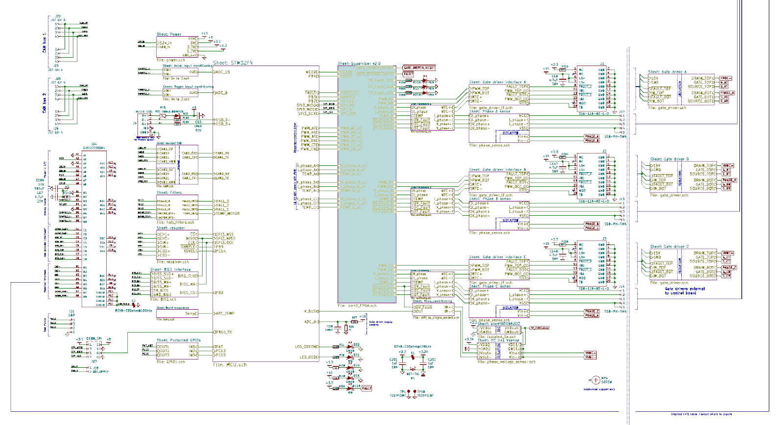
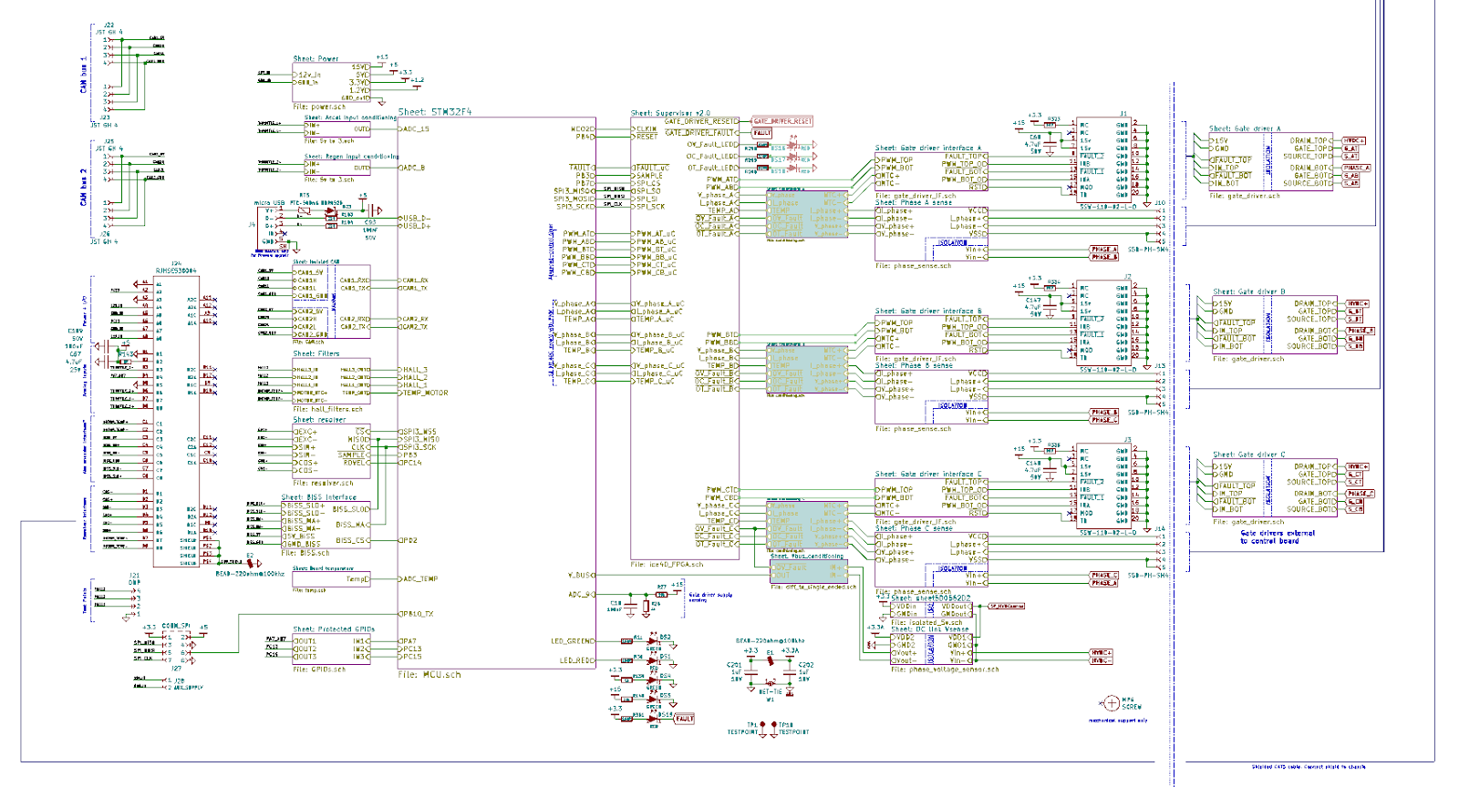
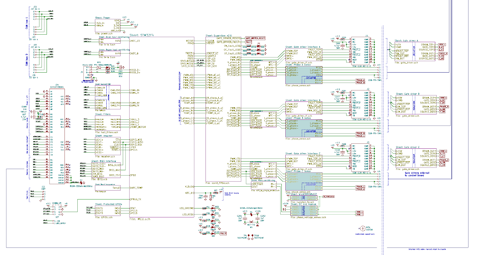
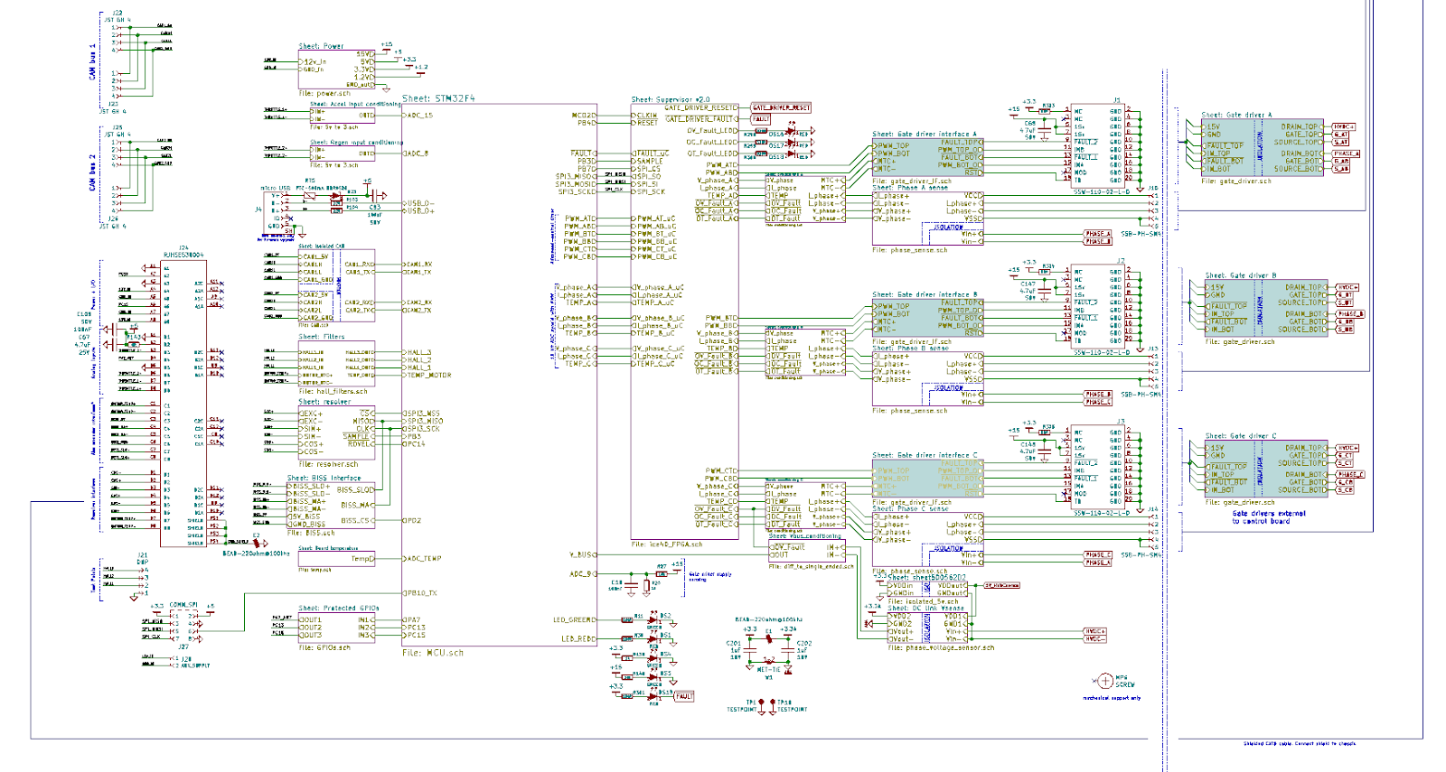
The intent of the system block diagram is to highlight key components or subsystems, power/signal flow of interconnected assemblies and draw the reader's attention to how the components fit into the wider system. In order to read a block diagram (or detailed schematic), you would generally expect it to flow from left to right, with as much attention to the important details as possible.
Power Stage
In the top of the diagram you can find the powerstage of the inverter, generally consisting of the components exposed to high amps. From left to right you see:
- Terminals for the battery inputs. (BATT+, BATT-)
- A pair of isolation contactors (safety feature) and pre-charge resistors to limit the current during initial charge of the DC Link capacitor. (K1A, K2A, R32, R152)
- Voltage sensing of DC bus which is required for field oriented control (HVDC+, HVDC-)
- Automatic discharge of DC Link capacitor when system turned OFF or loss of MCU power.
- 600V 650uF DC Link capacitor, in this picture it is shown as three separate capacitors
- 650V 600A IGBT modules, mounted on a heatsink with thermal interface material
- 3 In-line phase current sensors, high bandwidth hall effect
- Active cooling system
- PMAC 3-phase motor
The powerstage shown is very specific for a particular configuration with 650V 600A IGBTs, but the customer can use a different powerstage, the control board is agnostic in this regard, with minor hardware changes the Axiom control board can be made to support other voltage or current ranges.
DC Link capacitance, ripple current and technology are chosen based on the application requirements (motor inductance, switching frequency, temperature, etc). For high voltage, power dense application metalized polypropylene (MPP) film capacitors are used. This type of capacitor not only has self healing capabilities, it is also capable of delivering a tremendous amount of instantaneous power due to extremely low internal impedance. The close proximity between DC Link capacitor and IGBT switches also minimizes the parasitic inductance which is critical for overall system performance.
For high performance drives 3 phase current sensors are necessary, they allow the control algorithm to manage signal noise and also to detect faults to ground. Furthermore, the use of three independent phase current sensors allow for controlling naturally occurring imbalance which otherwise not be available in a system with two sensors.
Control Inputs
On the left of the diagram there are user inputs
- CANbus interfaces. Redundant, isolated CAN bus. Supports UAVcan protocol and native VESC protocol at 500kbps.
- RJ45 1: 12V power input + digital I/O. The board can be supplied from 9Vdc to 28Vdc, 3A external supply is required, it is recommended to use a 12V battery to supply these subsystems. The board will generate all necessary control power such as 15Vdc for the gate drivers, 5V and 3.3V for the logic.
- RJ45 2: Analog inputs. Can be configured to be used as accel/regen inputs or sin/cos encoder.
- RJ45 3: BiSS absolute encoder port.
- RJ45 4: Resolver port.
- Hall sensor interface. This is not an appropriate position feedback for a high power, high performance drive, its there for testing purposes.
- USB port only for programming, not suitable for controlling a motor.
- SPI interface: internal SPI bus is available for very high speed expansion. In the existing design this interface is used for high speed communication between FPGA and MCU.
The fast switching of high voltage and/or high current can generate a considerable amount of electromagnetic interference (EMI). It is imperative that the input signals be protected against transients which is why the RJ45 type connector with CAT5 cable was chosen. CAT5 cable provides twisted pair with optional shielding which is ideal for signal integrity. CAN bus connector is the same as defined by UAVCAN specifications for direct mechanical compatibility.
The preferred interface for controlling a motor with an Axiom board is the CANbus as it provides CRC integrity checks, needs less wiring, can withstand more EMI than an analog signal and provides full access for both commands and readouts of the drive operation. Furthermore, as an open source product new CANbus commands or feedback can be easily accommodated with code future code customizations by the user.
Microcontroller Block
VESC uses an STM32F405 microcontroller which has the following capabilities:
- 168MHz ARM core
- 1MB flash
- 192KB RAM
- 12 bit ADC
- 12 bit DAC
- Advanced PWM
- Built-in USB DFU bootloader
- Open source toolchain, make and gcc based workflow.
- VESC firmware with 100,000+ lines of code and a RTOS.
The core of the system is the STM32 microcontroller, a high performance device that deserves its own post explaining the inner workings of VESC.
FPGA Block
While early versions in our design history used discrete logic, Axiom relies on an iCE40 FPGA from Lattice to perform continuous safety checks in fault inputs and pwm outputs. FPGA based protection allows for highly configurable and robust fault protection far exceeding simpler discrete methods.
Some highlights of the FPGA:
- QFN package
- 5280 Logic elements
- 1MB RAM
- SPI for on-boot configuration and data transfer.
- Internal PLL to boost clock up to 275 MHz
- Lightweight, open source toolchain
The FPGA has sufficient capacity to implement complex accelerator peripherals, like encoder decoders, digital processing; even a RISC V cpu softcore fits inside the fabric. It’s a great opportunity for research teams to push the boundaries.
Analog Signal Conditioning
The light blue highlighted blocks shown in the above picture receive raw, differential analog data which is filtered, converted to single-ended signals. Differential signal delivery was chosen due to their inherit common mode noise rejection and allow for larger voltage ranges. The conditioned signals are sent to ADC pins for further software processing, and they are also sent to a hardware based fast acting protection circuit in case of overcurrents, overvoltages or over temperatures. No software intervention needed.
High Voltage Sensing
Isolated inputs are used to sense the motor and battery voltages. Complies with clearance and creepage to work at 800V and uses an AMC1301 for reinforced isolated sensing.
Very high CMRR is required in applications with Silicon Carbide mosfets, and these isolators are well suited for those applications.
The battery voltage is constantly being used to compensate for ripple in the dc bus, and also during motor parameter detection. Phase voltage sensing measures the BEMF when the motor is released so the phase observer algorithm keeps track of the motor angle. That way, when the motor is released and suddenly the user commands full torque, the control loop knows exactly the motor position and can instantly apply the precise current vectors. Other uses include motor position feedback sensor calibration (encoder, resolver) and to monitor feedback failures during runtime.
PWM Output and Gate Drivers
The isolated gate drivers are external to the control board carefully matched to the IGBT installed. 3.3V PWM signals are generated by the microcontroller, processed by the FPGA and then are buffered and level shifted to 5V for higher noise immunity.
Follow us for more updates!
Discussions
Become a Hackaday.io Member
Create an account to leave a comment. Already have an account? Log In.
hi , FPGA code isnt it made public yet?
Are you sure? yes | no
Very interesting! Would enjoy seeing a longer writeup on the capacitor you're using.
Are you sure? yes | no
Stay tuned! There are nice ESL simulations and math around that cap
Are you sure? yes | no