deʃhipu
-
All the Buttons
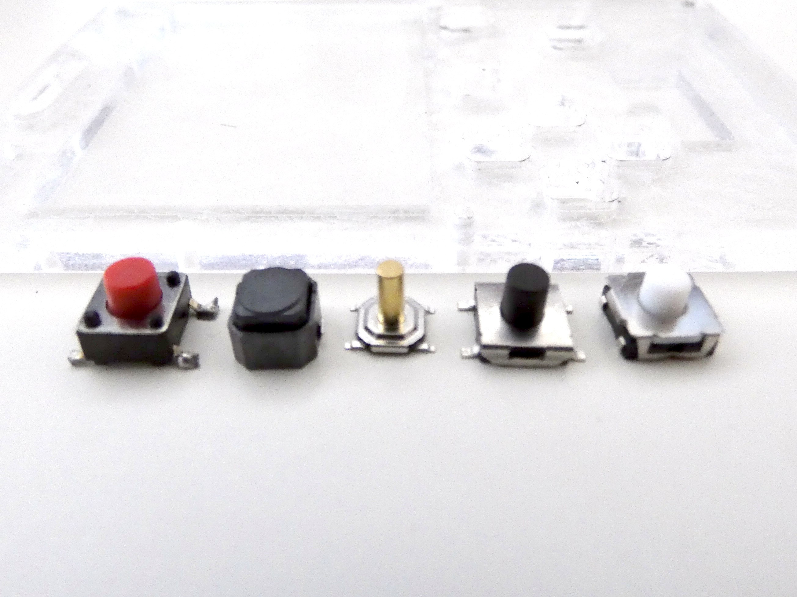
09/21/2019 at 11:12 • 0 commentsWhile @Elecrow is taking their time with the order (still in production after 10 days), all the buttons arrived for testing. I really like the idea of laser-cut button caps, but if that doesn't work, I want to have some other options, so testing continues. The buttons look like this:
![]()
From the left: the original 6x6x6 button I used in PewPew, the silicon switch I used in µGame, those horrible 4x4 switches that dig into your fingers, low-profile 6x6x5.5 switch, and ALPS SKRAAME010.
In the back you can see one of the cases I experimented with, with two layers, bottom 2.5mm and top 1mm.
Some immediate conclusions: the metal one will need keycaps one way or the other. The two low-profile buttons might work without (especially the ALPS, that has silicone cap), but seem a bit narrow. The ALPS button is minimally higher than then 2.5mm required to fit under the top layer.
I will need to wait for the prototype to be able to say anything more.
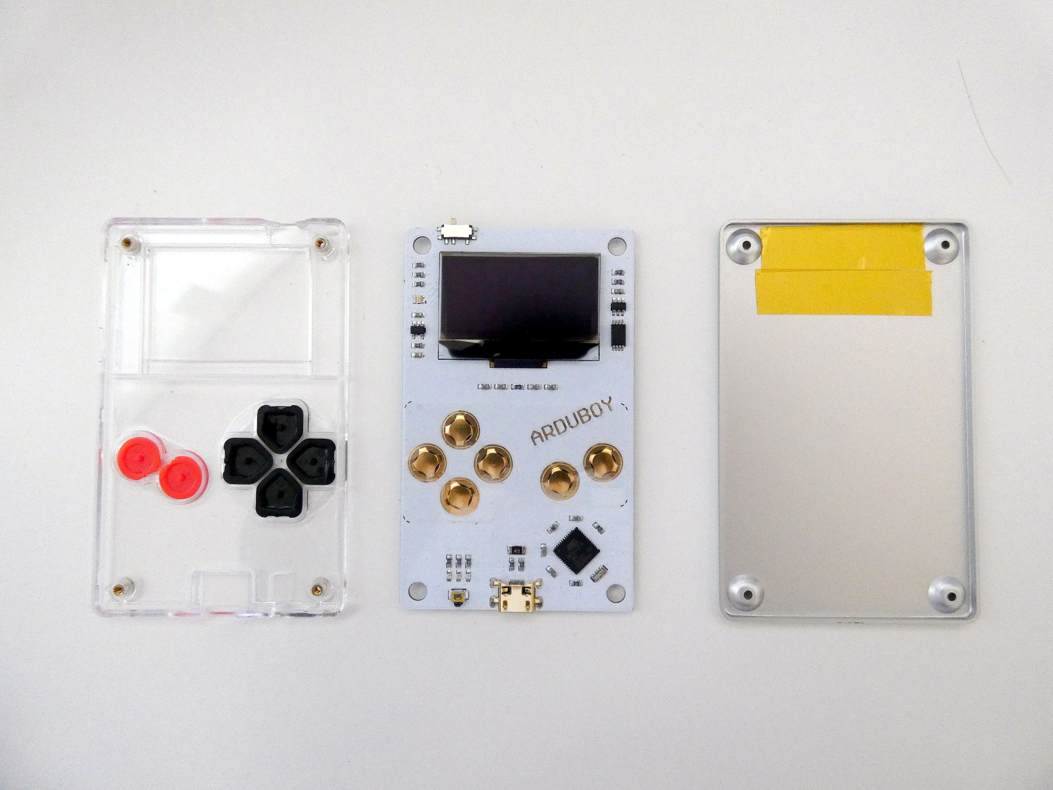
---------- more ----------In other news, I'm also taking a look at the competition: in this case, one of the oldest homebrew consoles out there, the Arduboy:
![]()
Some interesting things to note here: they have brass nuts sunken in the plastic for the bolts — that probably makes it impossible to crack like it did for me. Buttons use plastic caps, but underneath are just simple metal domes, glued to the PCB with a sticker, not even soldered. The USB port is interesting as well, because it's sunk into the PCB's cutout.
![]()
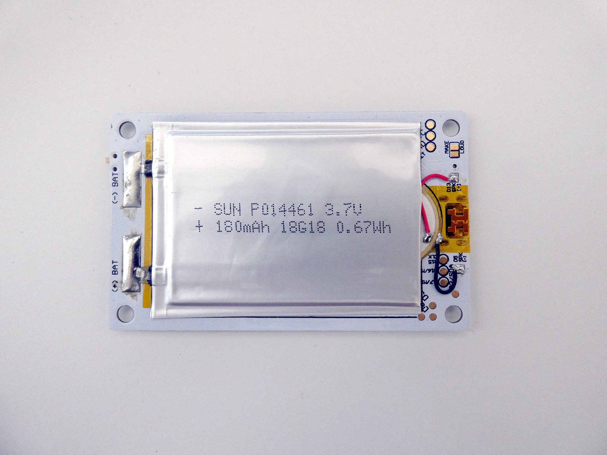
The other side is mostly a super-thin LiPo battery, with horrible soldering, and a piezo stuck under it. Kapton tape guards against shorts to the metal back.
-
Prototype 6 on Order
09/11/2019 at 15:11 • 0 commentsI was actually so excited about the idea with laser-cut button caps, that I scrapped the design for version 5 that I had lying around, waiting for the new buttons to arrive to make sure I have the right footprints, and made a version 6, going back to the standard tact switch buttons, with an SMD piezo:
![]()
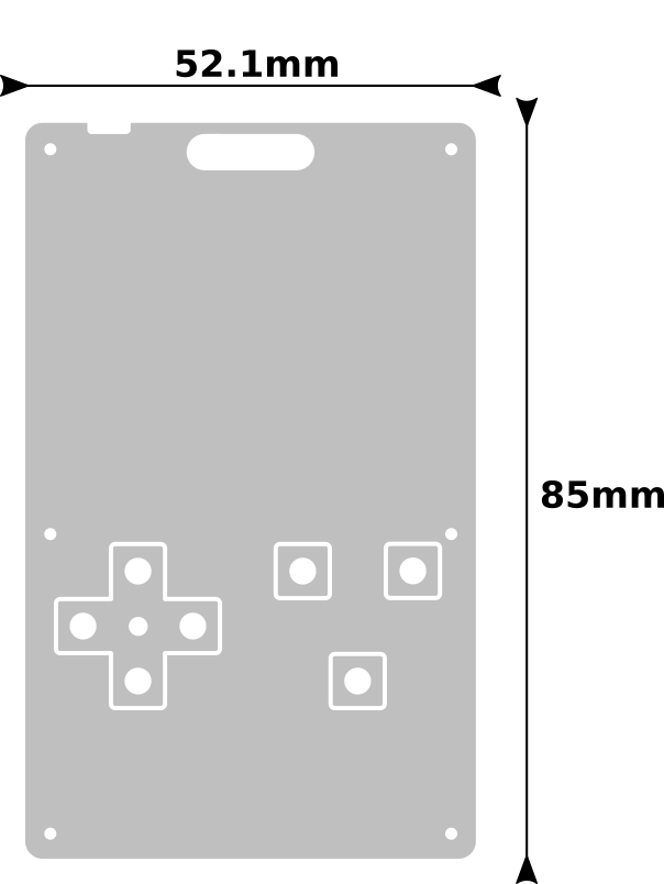
I also moved the holes a tiny bit away from the edges, to make the acrylic a bit stronger, and added a hole in between the d-pad buttons, so that I can experiment with placing a plastic bead in there, so that the d-pad cross can tilt on it. We will see how that works.
The top plate of the case now has cutouts for the button caps and the caps themselves:
![]()
I also included a second version of those caps, with a cut across the hole to increase springiness, in the middle plate design. We will see which one works better. I will probably need to tweak the hole sizes a little bit anyways.
There is also rubberized sticker paper that I can put on top of the caps, to cover the holes and make the surface better for the grip. I will be experimenting with that later on — I'm still toying with the idea of having a sticker in between the layers, then the cap covers could come from that too. Seems like you can get custom 10x10cm die-cut stickers easily.
-
Laser-cutting Button Caps
09/10/2019 at 18:56 • 0 commentsAs mentioned earlier, I either need to find a way to have a thicker front plate on the case, or a better way to attach the thin front plate, that won't make it break at the screw holes. Last time I experimented a bit with gluing the front plate, but that doesn't look good. I could try another approach: replace the acrylic plate with a transparent sticker. But before I go there, there are also several ways I can use a thicker plate.
I already have several different kinds of button switches on order — ones that are more clicky that the current ones, but also have their business end sticking higher, while having their base still fit in the 2.5mm space I have under the front plate. This is actually the biggest problem, as most tact switches out there have their base 3.5mm high. But even if those new switches work fine, there are still some problems with this approach: the surface area of the place where you press your finger is not very large, and those special switches will probably be difficult to source — that will hurt the reproducibility of the project.
Another approach is to use standard tact switches, but have button caps on top of them, that will make them both higher and wider. They could also cover the hole that would need to be cut in the top plate for their 3.5mm high bases. So I also have two kinds of such caps on order, and we will see how well those work.
The last possibility is the most interesting one: those button caps are nothing more than pieces of plastic with a hole in them for sticking on top of those switches. The hole is slightly conical, and the plastic a bit springy, so once you push them in there, they stay. What if we laser-cut out button caps from the same material as the case? We have a large hole for the display, we could put some additional shapes in there. And we could make them in the shapes we actually need — a cross for the d-pad, and some rounded rectangles for the fire buttons. The only problem is that they would have this hole where the switch goes, but that might actually not be that bad (adding extra texture for grip), and if it is, I could put some rubberized stickers on top, maybe? Also, the laser-cut holes are naturally a little bit conical (because of the laser's colimation).
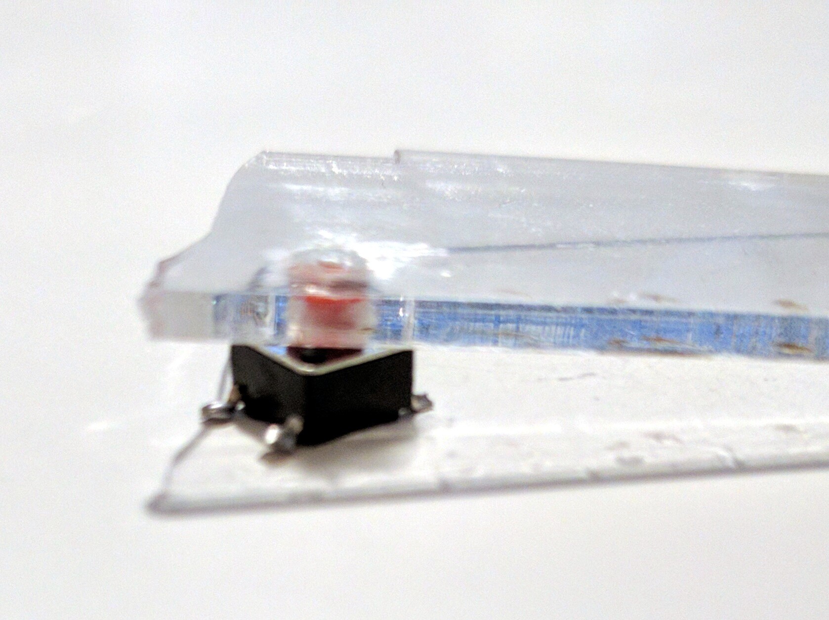
Since I don't have an easy access to a laser-cutter, I decided to make a quick test by manually drilling a hole of the right size in a piece of acrylic, and sticking it on a tact switch. The closest size of the drill I have is 4mm, which turned out to be ever so slightly too small, so I used a reamer tool to make the hole a bit larger (and conical).
![]()
The first observation: since acrylic is not as malleable and elastic as ABS, the switch didn't stick in the hole. I could probably improve it by having a small cut in there, to make the hole more springy. But instead I just put a drop of acrylic glue on the top of the hole, and it sticks. There is enough wiggle room to make it work properly, and I might add a bead in the center of the d-pad cross to make it work like a real d-pad.
The hole on top doesn't feel unpleasant to touch, and I could probably add some more holes around it for a more consistent texture. I think this is an interesting direction, and I might give it a try.
-
Screws Again
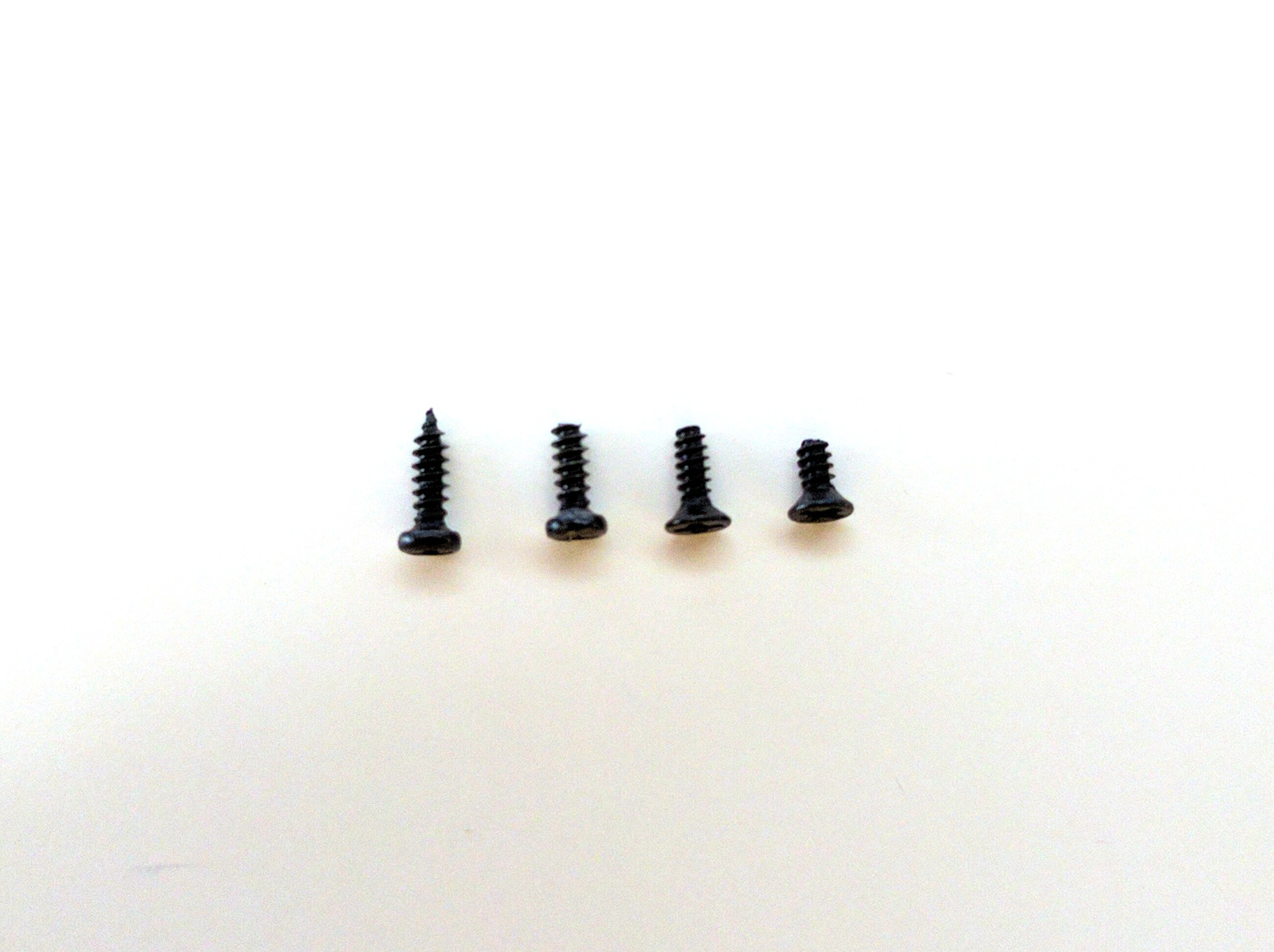
09/04/2019 at 19:46 • 0 commentsThe screws have arrived, and they are good. The 4mm long ones are just the right size to go into the middle layer, and the 5mm ones are perfect for holding both layers. Of course now I am in the process of rethinking that front layer anyways, but if I keep using screws, I know where to get them.
![]()
From the left, the original screw I used, the same kind with its tip cut off to make it not stick out of the case, the new 5mm screws, and the new 4mm screw.
-
Playing with Glue
09/02/2019 at 16:50 • 7 commentsSince I still have a couple of the laser-cut parts left from prototype 3, I decided to make a simple experiment to see how bad they would look like if I simply glued them together with instant glue. Here are two attempts:
![]()
The first is using gelled glue, and applying only a little bit of it on the middle layer, then pressing the two layers together. The second is using liquid glue, covering the whole middle layer with it generously, and then pressing the layers together.
I think the first one is completely unacceptable. The second one looks better (the glue traces that are visible are actually not from the glue in between the layers, but my fingerprints from handling the part with dirty fingers). A huge problem with the second one, however, is the excess glue that accumulated in the corners.
Unless there is a special way of doing this on industrial scale, for example with some special machine, I don't think this is a viable direction.
-
Workshop Damage
09/01/2019 at 22:45 • 2 commentsOver the weekend we were running some workshops using the #PewPew Standalone, and I brought the version 4 prototype along to show it to people. I carried it both in my pockets and in a box full of tools, and then it went through a lot of hands, including a couple of kids. This is a great sample of the kind of handling I expect from this device, so it was a nice wear-and-tear test. Unfortunately, the results are not very good.
![]()
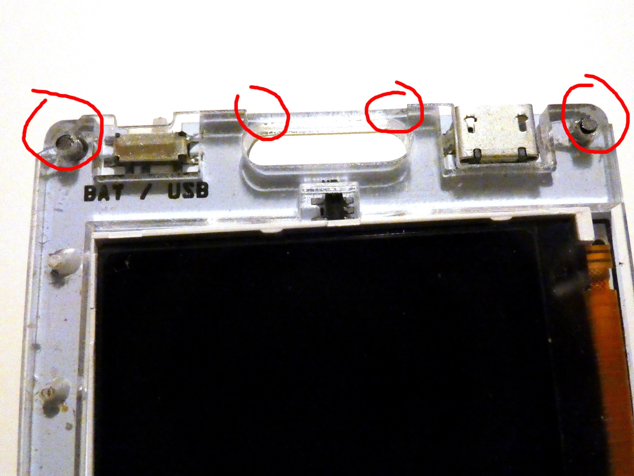
The 1mm thick acrylic cover is certainly a weak point. The two top corners broke away, and the two bottom ones are already cracked and ready to break as well. Also, the bar on top of the lanyard hole broke off.
I could move the holes further down and maybe a bit towards the center, to have more material there, but I think the whole idea of holding down a 1mm acrylic sheet with self-tapping screws like this is flawed. The top bar is not a problem — I can remove it completely from the top layer. But I think I need to come up with a better way of holding the two layers together (and then have the screws only hold the middle layer, which is 2.5mm and shows no signs of cracking).
Glue is an obvious option, of course, but I'm afraid it could work badly with the fact that the top plate is transparent, resulting in a surface with visible bubbles and/or clouding, which wouldn't be too nice to look at. A particularly interesting option would be to use an acrylic with pre-applied adhesive tape on it — also because then the tape could give me an additional 0.1mm of thickness that I need for the USB port.
Another option would be to forget the laser-cutting, and instead go for injection-molded case. I could then have the whole thing in one piece, with the exact dimensions I need, with proper transparency, and probably much cheaper in bulk as well. Also, rounded edges. Also, I could probably even incorporate the battery holder in the case itself, which would get rid of a tricky assembly step. The problem is that it would be quite expensive in small quantities, as the most expensive part is the mold itself.
Yet another option would be to use thicker top layer, and simply find buttons that would work with it better. I might go on another button-buying spree and see if I find something that would have a body that fits in that 2.5mm space, but has the button itself sticking more than the 2mm of the top layer.
-
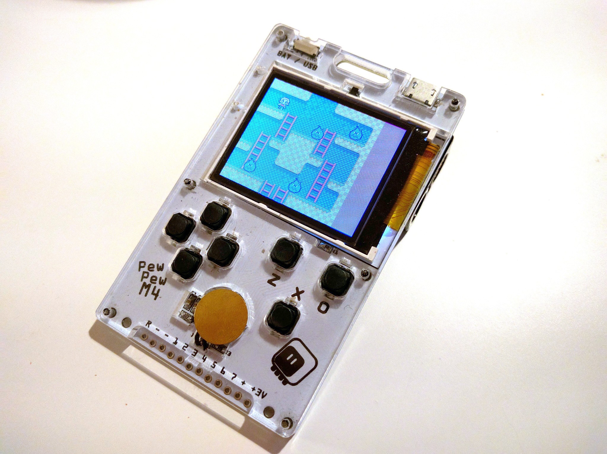
Prototype Version 4
08/30/2019 at 23:33 • 3 commentsThis time the assembly took me longer than usual, for two reasons.
First of all, I couldn't get the QFN chip soldered properly, somehow getting shorts or bad connections, despite having nice long pads and using a hot air gun and lots of flux. Took me some hours.
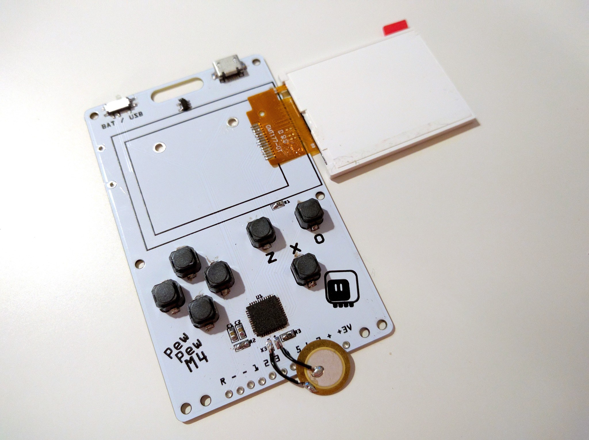
![]()
Second, I somehow managed to delete the two holes next to the display in the inner layer of acrylic, which are needed to fit the pins of the battery holder, when it's soldered on that side. I'm using new batch of battery holders, that have actual pins, and not wires, and they have the pins reversed compared to the previous batch, so they have to be soldered on that side.
In any case, it all fits together and holds nicely, and this time the buttons seem to be high enough. The cut-out for the USB plug doesn't look too bad, but the hanger part is quite fragile in the 1mm outer acrylic layer — I might modify the design to remove it from that layer, and only have it in the PCB and inner acrylic.
![]()
I'm still considering using a different piezo speaker — an SMD part, HYG7525 (aka XNQG 7525). It would go somewhere near the edge of the PCB, and it would have its own cout-out in the inner acrylic layer. It's exactly 2.5mm high, and the hole is on the side, so no cut-out in the outer layer would be necessary. It would make the assembly a little bit easier.
After the weekend, I'm going to publish the design files for version 4, because I think it's good enough to use. I'm going to build a few of those, and we will see how they work in the longer run — there might still be version 5.
-
Parts
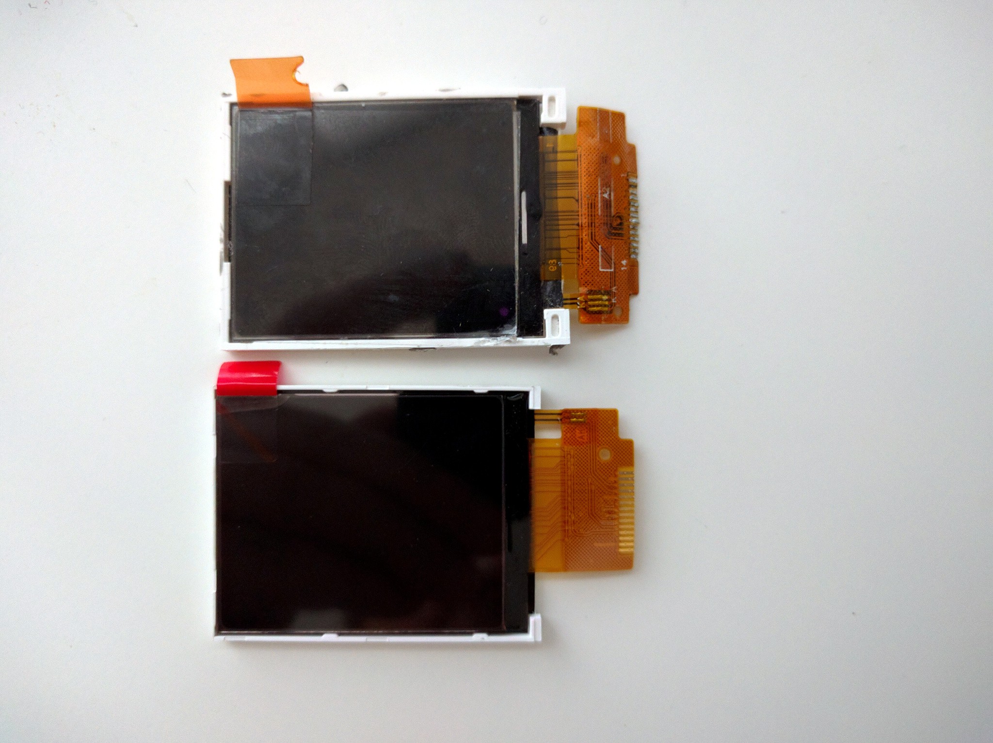
08/28/2019 at 21:26 • 0 commentsNot much actual work done, but some packages started to arrive. One of them is a new batch of the displays. They seem to be slightly different from the ones I had before:
---------- more ----------![]()
(Top one is an old one, bottom one is the new one.) While they should be compatible, and the flex connector ends at the same length, the plastic enclosure of the display is a bit shorter. Which is fine by me, because that means it won't be close to the edge of the PCB. But will the new display work as well as the old one? I quickly soldered one to one of the version 3 prototypes to test:
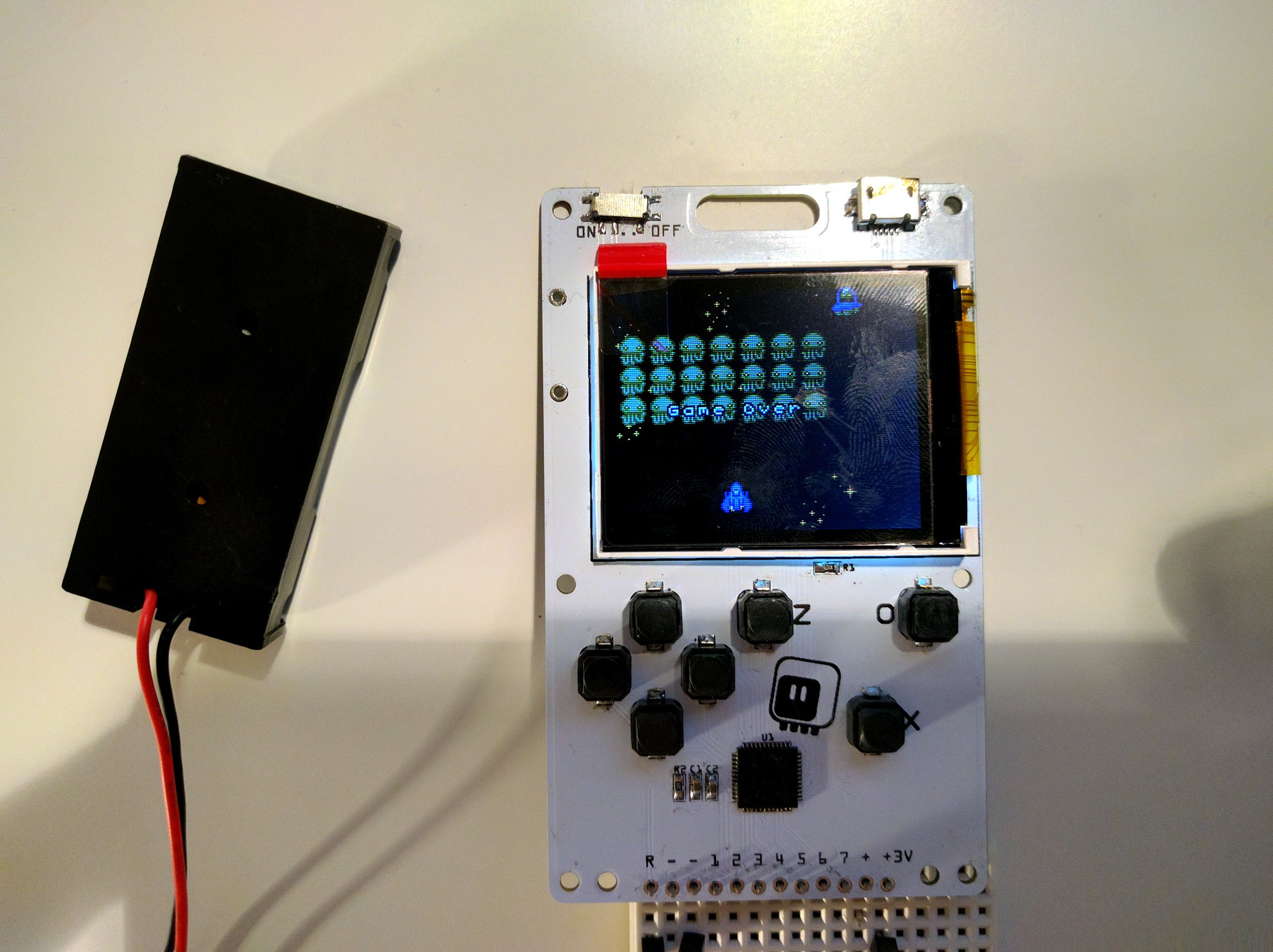
![]()
Seems to be perfectly fine. They also come with a much better adhesive tape on the back, so maybe a version without the case will be actually viable for them.
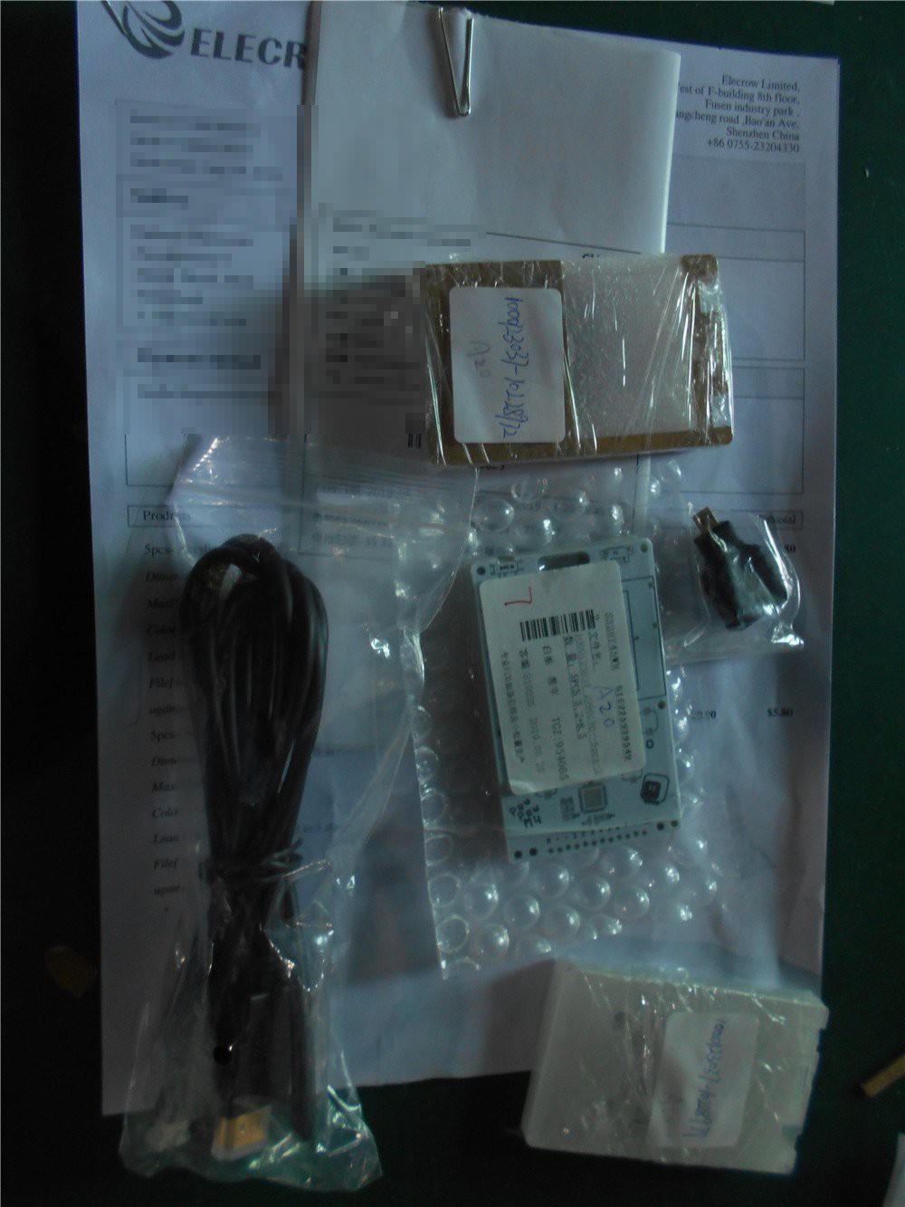
In other news, the PCB and laser-cut pieces for the version 4 are on their way from @Elecrow already:
![]()
Can't wait to see how they fit together.
-
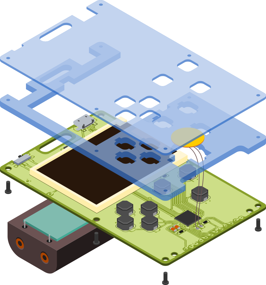
Eye Candy
08/26/2019 at 23:13 • 0 commentsI'm still waiting for the order from @Elecrow — it's taking longer than normal, probably because of the non-standard 1mm acrylic. In the mean time, I decided to work a little bit on the assembly instructions for the manual. I could make a rendering in OpenSCAD or FreeCAD, or even in Blender, but in my experience rendering are never as clean as pictures — they have too many irrelevant details. So I decided to just draw it all in Inkscape, using Fritzing's SVG exports and the cool features Inkscape has for the isometric view. Here's the result:
![]()
The colors are artificial, to make the drawing easier to parse — in reality all the parts are either white, black or transparent. The wires for the piezo speaker are also too long — but that was the only way to show how they have to pass through the hole in the middle part of the case.
-
Version 4 Ordered
08/18/2019 at 22:50 • 0 commentsI just made the final fixes for the next version: moved the "z" button closer to the "o" and "x" buttons, made contacts and cutout for the piezo speaker (and a resistor for it), added a footprint for a voltage regulator. I also increased the sizes for the button holes so they should be easier to fit now, and moved the display minimally further from the edge, to make sure the flex tape doesn't stick out. Oh, and made a cutout for the USB port in the top plate, as it's slightly thicker than 2.5mm, and I don't feel like filling it down to size. Also added labels for tx/rx pins on the back, and made the screw holes in the inner plate smaller, so they will also be caught by the screws — to compensate for the thinner top plater.
I specified the top plate to be 1mm thick, we will see if they follow the instructions.
Everything else remains pretty much as it was.
![]()