 Gabriel D'Espindula
Introduction
Believe you or not, I've used a brand new microwave to do this. I've looked for the cheapest option with numeric digital keyboard and display I could find in UAE and got this model:
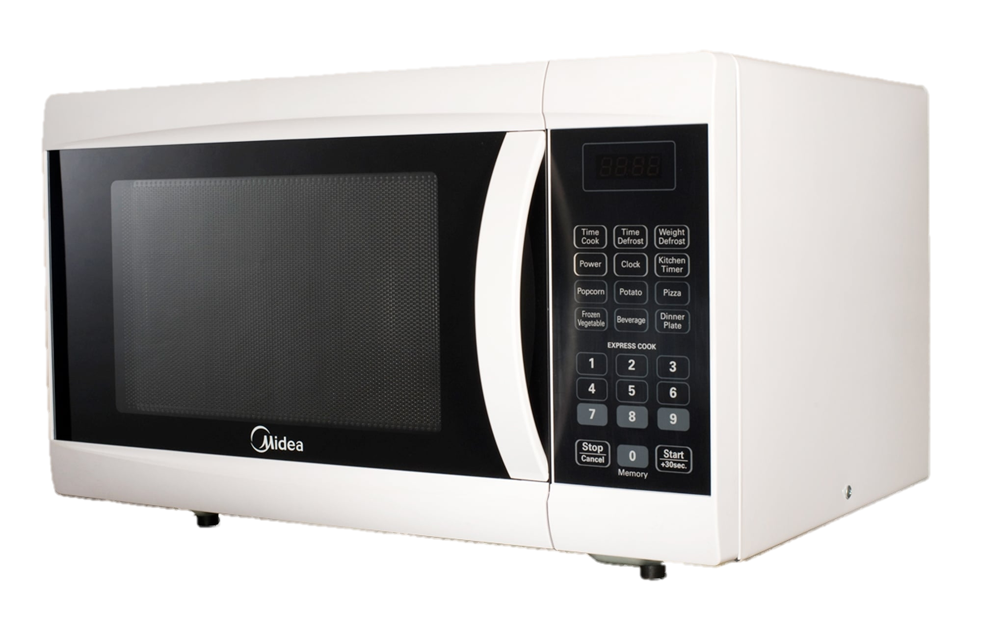
Honestly I never heard of this brand before, but the model was perfect for me!
First step was opening the machine. Second step was trying to understand how it works.
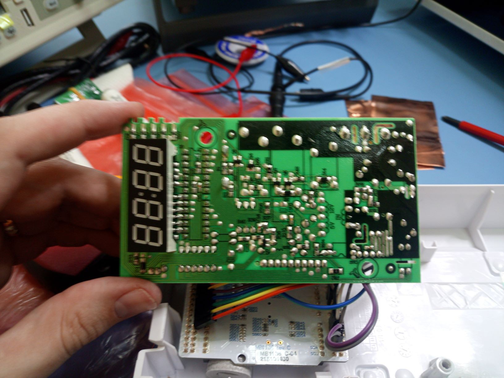
I didn't try to find the schematics online, tried to understand the circuit by myself (not really difficult, right?) and I got really surprised how fun it is! It has several hardware safety features. I'll talk about them one by one, but let's start by what I've found in the microcontroller's pinout:
| IC1 pin | Function |
| 1 | Keyboard line 2 |
| 2 | Keyboard line 1 |
| 3 | NC relay |
| 4 | Microwave generator relay |
| 5 | Motor and light relay |
| 6 | Reset |
| 7 | GND (Vss) |
| 8 | NC |
| 9 | Display CC4 |
| 10 | Display CC1 |
| 11 | Display CC3 |
| 12 | Display CC2 |
| 13 | ???? I have no idea what it does |
| 14 | Display segment A / Door |
| 15 | Display segment B |
| 16 | Display segment C / Keyboard column 6 |
| 17 | Display segment DOT / Keyboard column 5 |
| 18 | Display segment D / Keyboard column 4 |
| 19 | Display segment E / Keyboard column 3 |
| 20 | Display segment F / Keyboard column 2 |
| 21 | Display segment G / Keyboard column 1 |
| 22 | +5V (Vdd) |
| 23 | 4MHz Crystal |
| 24 | 4MHz Crystal |
| 25 | Buzzer |
| 26 | Keyboard line 3 |
| 27 | Keyboard line 4 |
| 28 | AC frequency in |
Of course the part number was scratched, and I couldn't figure out what is this microcontroller considering Vdd, Vss, reset and crystal. If you know, make a comment!
Anyway, as my goal was to substitute the uC, I didn't spend much time searching for that.
Fun solutions found
One by one I'll point all features I noticed and liked. For some of them I'm not sure about the real reason but I'll raise some possibilities, if you know the actual reason put in the comments!
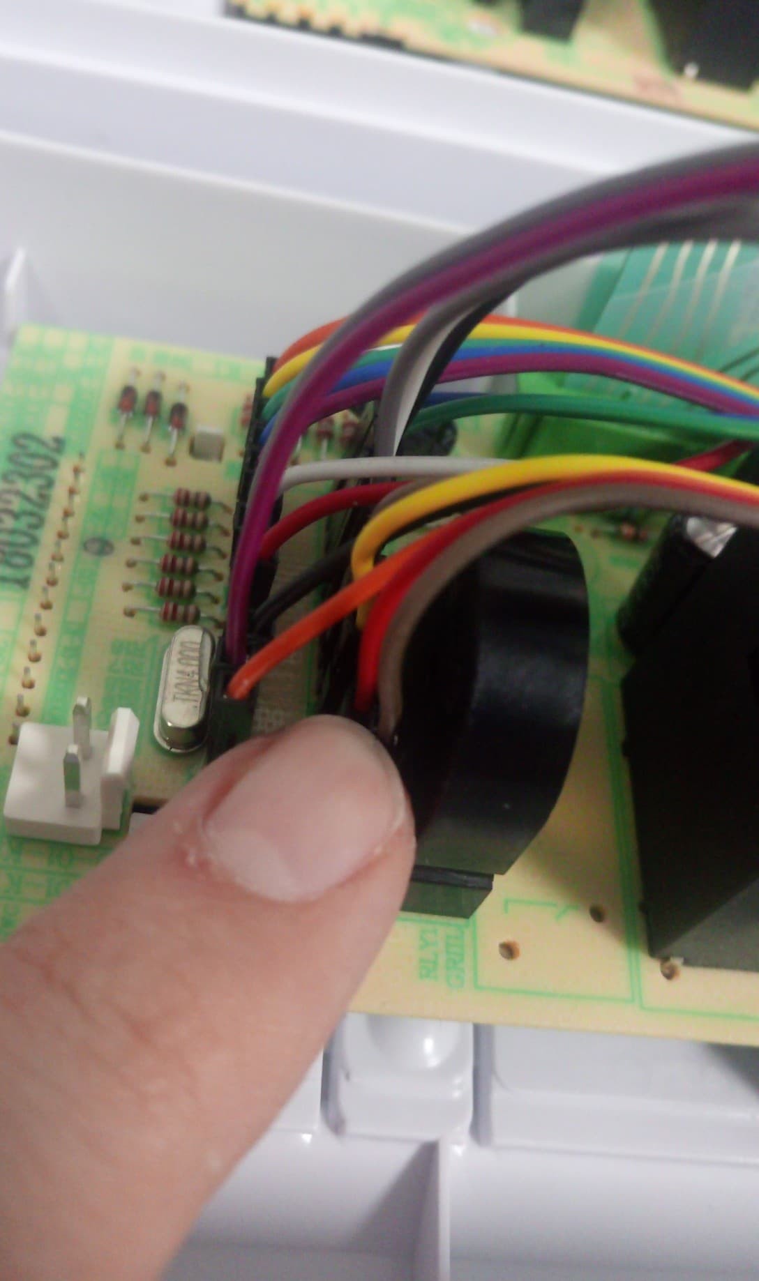
Shared pins: The first nice feature was that most segments (anode pin) share pin with the keypad. While I was capturing the schematics and saw this I was very excited to alternate between inputs and outputs to make it work (as the code bellow). As @Ken Yap remarked in the comments bellow, it's not necessary to do so. Even being some obvious option to reduce pins I never thought about it when doing my own designs.
My solution in the firmware was creating a postscale inside the timer interruption handler with 5 steps as the quote bellow:
switch(postscale%5){
    case 0:
        print7seg(display[0]);
        setApin(OUTPUT);
        DS1(0);
        break;
    case 1:
        DS1(1);
        print7seg(display[1]);
        DS2(0);
        break;
    case 2:
        DS2(1);
        print7seg(display[2]);
        DS3(0);
        break;
    case 3:
        DS3(1);
        print7seg(display[3]);
        DS4(0);
        break;
    case 4:
        DS4(1);
        last_key=key;
        key=readKey();
        setApin(INPUT);
        door=HAL_GPIO_ReadPin(DOOR_PORT,DOOR_PIN);
        break;
}
postscale++;
Buzzer: This was one of my favorite things. The buzzer doesn't have an internal oscillator, and is possible to use it as a polyphonic speaker. I didn't implement that, but the fist thing came to my mind was a super mario themed microwave hahaha every key press is a coin catch and star power sound ring if time set is lower than 10s!
Motor and light: This feature is actually very interesting. The first point here is that internal motor and light are same signal and external switches make the door opened disable the internal motor. It means in the firmware is necessary to turn on this output every time the door is open (to turn on the light), but when the user closes the door is necessary to disable the light, otherwise the motor will start to spin. A simplification of this connection is bellow:
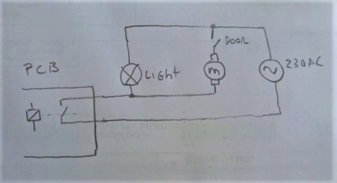
Guess that's why the light turns off when the door is closed.
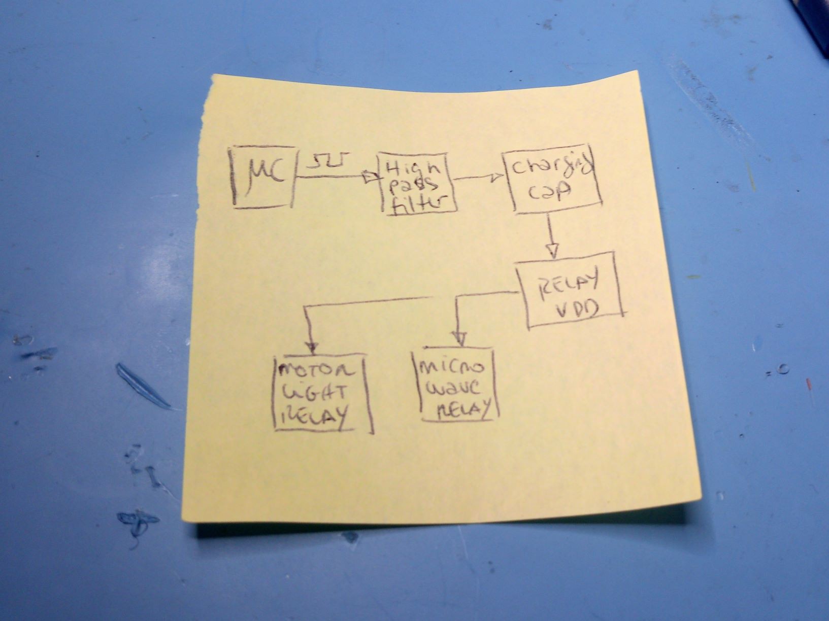
Hardware protection for firmware bug: This is one of my favorite features from this circuit. The "Motor and light" signal must be a frequency. It has a high pass filter that charges a cap in the output to enable a transistor. if you keep the signal high or low it switches off the voltage feed for the relays. I didn't translate the full circuit, but the blocks diagram works like this:
Door and microwave generator: For the microwave generator, beyond being enabled when the "Motor and light" is a astable out, is also necessary to keep the door closed, otherwise the relay that activates the microwave has the circuit disabled when the door is open.
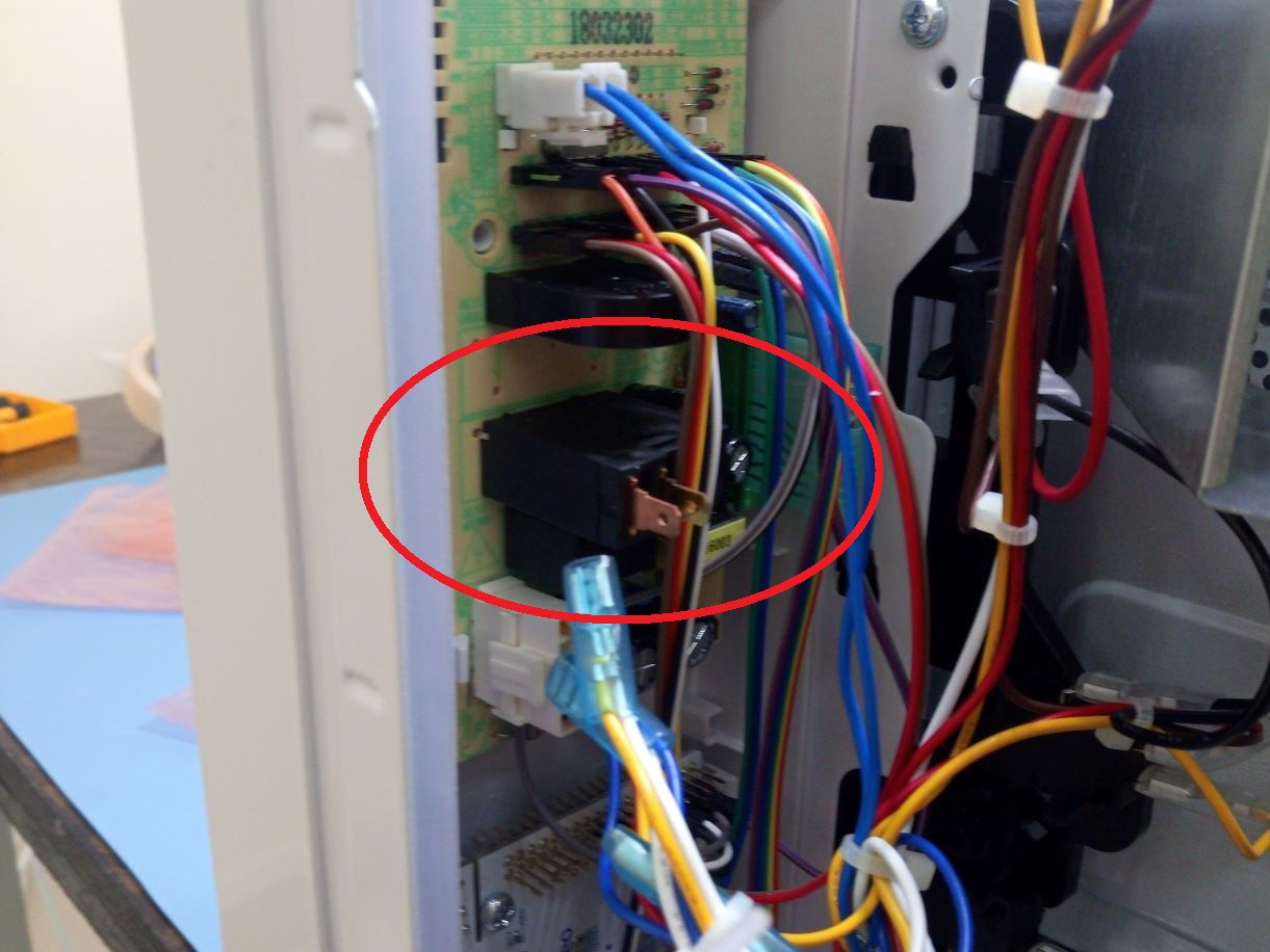
Power control: This is the most frustrating feature. I was really expecting some super cool power control system, but basically is a on/off system using a relay. Yes, if you set to 30s in 50% power it will turn on and off the relay and at the end the microwave generator will be on during 15s. But something I liked was the super fancy relay used for it!
Mysterious designs (at least mysterious for me)
If you know the reason for some of this features I found let me know in the comments!
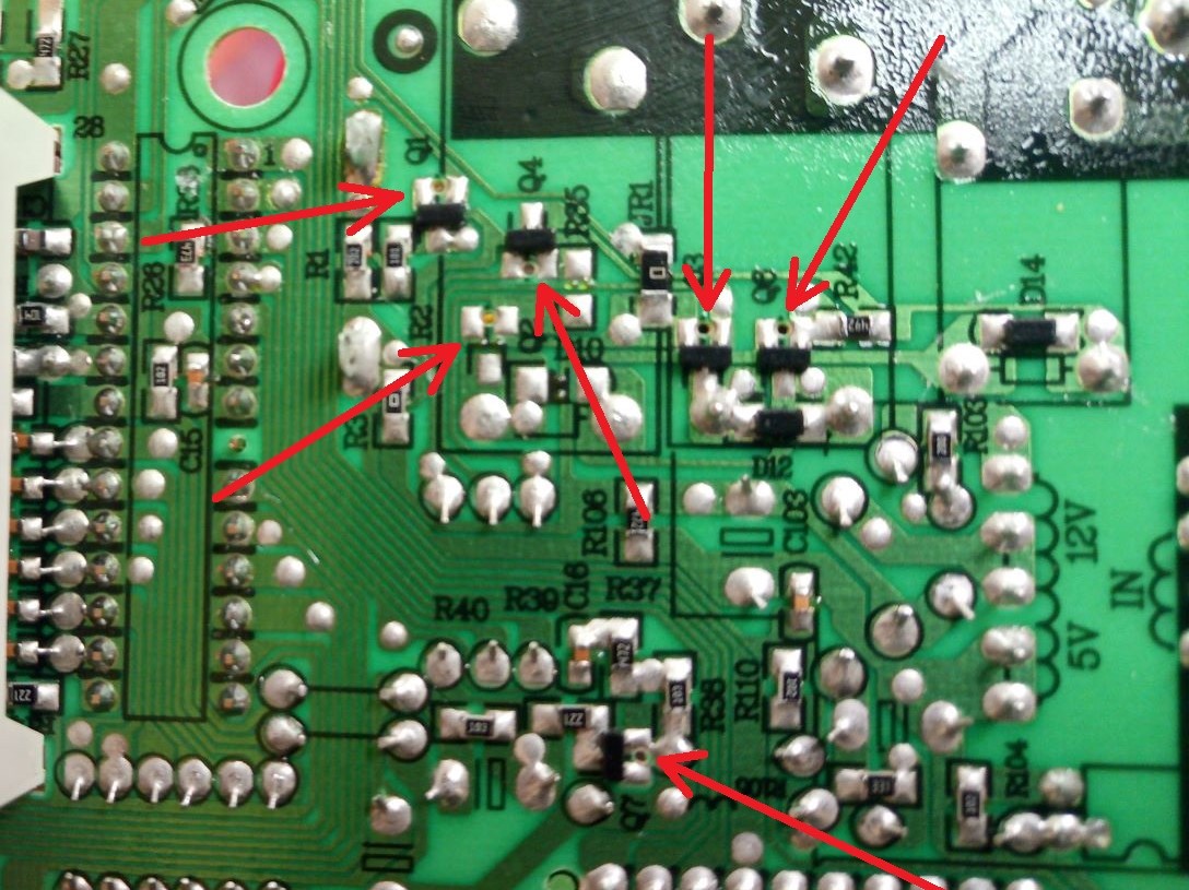
Holes between pads: I do have a good guess here, but I'm not sure if it's the real matters or not. Is it for avoiding shorts when soldering by wave?
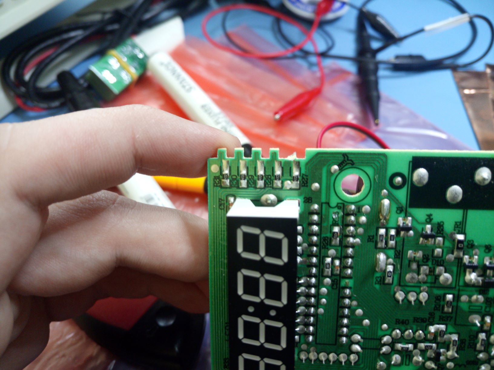
Broken tooth: There is a trace going there, and seems like it's to select a model with 4 displays, but I never saw a microwave using 5 displays, so I have no idea why they did that. Any ideas?
Frequency input: As you can see at the pins table there is a AC frequency input to the microcontroller. My first idea was that they had a terrible idea (used a lot some years ago) to use this AC frequency input as tick for the clock counting, but it has a 4MHz crystal, so it doesn't make sense.
My second guess was to use this to check if the input was correct according to the model (50 or 60Hz) does the wrong frequency damage the microwave generator? I have no idea.
My last thought was to use this pin as a prediction of the best time to turn on and off the relay comparing to zero-cross reference (to reduce current peaks and increase the relay lifespan). Does it make sense?