 Aitor Gómez García
Connecting it directly in a VGA output, it will bridge and convert the RGB signals to a passive equivalent luminance value with a few resistors, then you just have to select the monochrome output by combining the primary colors red, green and blue using the some buttons.
The luminance is calculated passively and approximately to the following formula:
0.2126*R + 0.7152*G + 0.0722*B
The schottky diodes are intended to prevent the RGB signal from going back and mixing when the switch is selected in color:
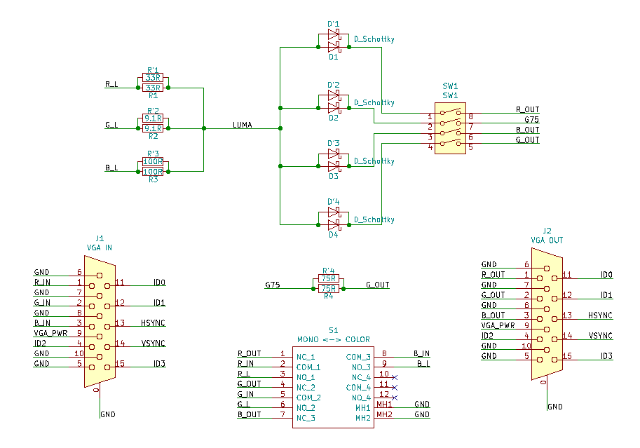
In a new improved and updated revision of the board, the double passive components shown in the diagram serve to have footprints with a mix of encapsulation technologies (SMD and TH), in order to make the assembly task more flexible.
All changes from first revision:
- The RGB resistors provided are 90% smaller in value. The filtered output signal is brighter, it can be considered an improvement.
- The VGA input connector is now also female, to prioritize use in a case and more accessible to the user. However, a Mini Gender Changer is also used but this time it must be male-male type, to connect directly to the video output or to the monitor input, and can be left permanently.
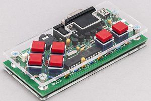
- New PCB design with through hole technology and mixed SMD, for an assembly task adapted to the needs of each one.
In the following video can be seen in operation with the first revision. The color mode display is affected by poor lighting, where saturated colors are displayed. With this lighting I wanted to highlight the monochrome mode:
Now with 3D case too, thanks to Agustin Gallego for designing it:


 Voja Antonic
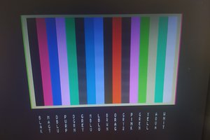
 Leon
Leon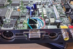
 Jacques Gagnon
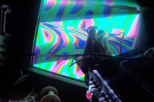
 Russell Kramer
Is there a BoM for this somewhere? specifically the type of diode (I'm an amateur so forgive me if there are no different types), and the two switches