Close
0%
0%

Spectrum Analyser Code

Code for a spectrum analyzer.

Similar projects worth following
Code for a spectrum analyzer.

The code is to be ported to an ATTiny85 to make a project.
Uses Goertzel's algorithm with a Hamming window.

Goertzel's Algorithm

This algorithm can be used to detect a frequency from sampled data.

Here is a link (http://www.mstarlabs.com/dsp/goertzel/goertzel.html).

Here is the preliminary code for a spectrum analyzer:

#include <stdio.h>
#include <stdlib.h>
#include <math.h>
// Uses Daniil Guitelson's BGI library
#include "graphics.h" // -lBGI -lgdi32


#define SampleFreq 125000


int main(void)
{
  int N=250;
  double data[N];
  double samples[N];
  double freq;
  double s;
  double s_prev;
  double s_prev2;
  double coeff;
  double magn;
  int i;


  int gd=CUSTOM, gm=CUSTOM_MODE(700,700);
  initgraph(&gd, &gm, "");
  setcolor(WHITE);


  int X1,Y1,X2,Y2;
  double scale,xmin,ymin,xmax,ymax;


  // Find the maximum and minimum data range
  xmin=0;
  ymin=0;
  xmax=50000;
  ymax=N;
  scale=1.1*(xmax-xmin>ymax-ymin?xmax-xmin:ymax-ymin);


  // Generate samples
  for (i=0;i<N;i++) {
    samples[i]=(50*sin(2*M_PI*i*3300/SampleFreq)+50*sin(2*M_PI*i*5700/SampleFreq)+50*sin(2*M_PI*i*25700/SampleFreq)+100);
    // Window the data
    // data[i]=samples[i]; // Straight Goertzel - not great
    // data[i]=samples[i]*(0.5-0.25*cos(2*M_PI*i/N)); // Hanning Window
    data[i]=samples[i]*(0.54-0.46*cos(2*M_PI*i/N)); // Hamming Window
    // data[i]=samples[i]*(0.426551-0.496561*cos(2*M_PI*i/N)+0.076848*cos(4*M_PI*i/N)); // Exact Blackman Window
  }


  // Scan frequencies
  for (freq=100;freq<=50000;freq+=100) {
    coeff=2*cos(2*M_PI*freq/SampleFreq);
    s_prev=0.0;
    s_prev2=0.0;
    for (i=0;i<N;i++) {
      // Goertzel
      s=data[i]+coeff*s_prev-s_prev2;
      s_prev2=s_prev;
      s_prev=s;


    }


    // Get magnitude
    magn=2*sqrt(s_prev2*s_prev2+s_prev*s_prev-coeff*s_prev*s_prev2)/N;
    printf("Freq: %6f Mag: %6.4f\n",freq,magn);


    // Plot data
    X1=(int)((freq-(xmin+xmax)/2)*700/scale+350);
    Y1=(int)((0+(ymin+ymax)/2)*700/scale+650);
    X2=(int)((freq-(xmin+xmax)/2)*700/scale+350);
    Y2=(int)((-magn*700/2+(ymin+ymax)/2)*700/scale+650);
    line(X1,Y1,X2,Y2);


  }
  getchar();
  closegraph();


  return 0;
}

I have used Daniil Guitelson's BGI library (https://sourceforge.net/projects/openbgi/) for the graphics.
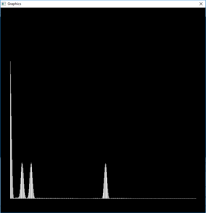
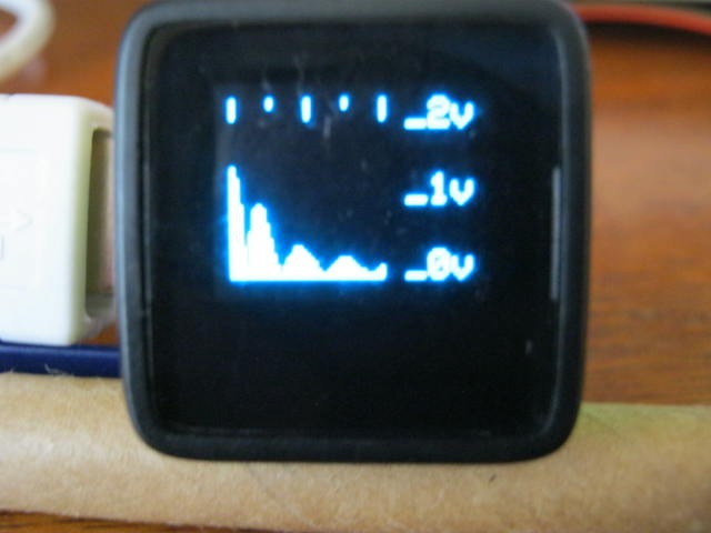
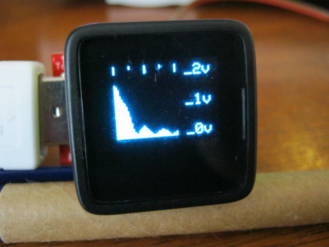
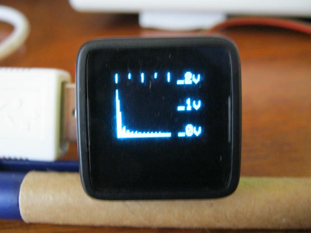
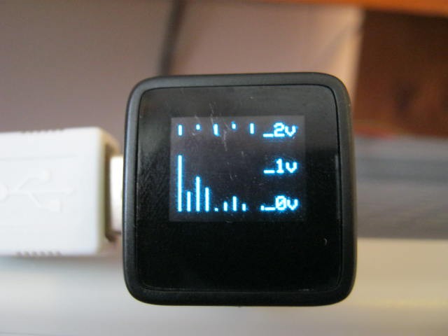
Output

Here is the output showing the DC, 3300 Hz, 5700 Hz and 25700 Hz signals:

Next Step

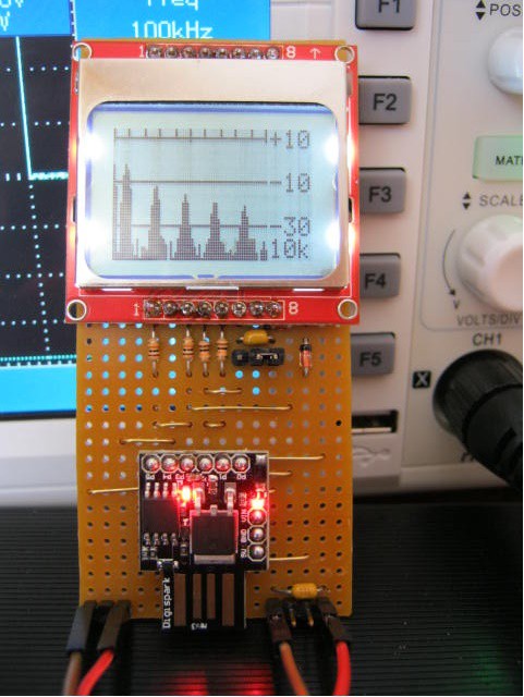
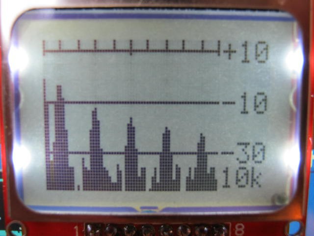
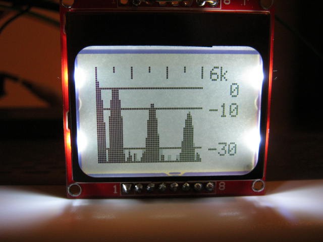
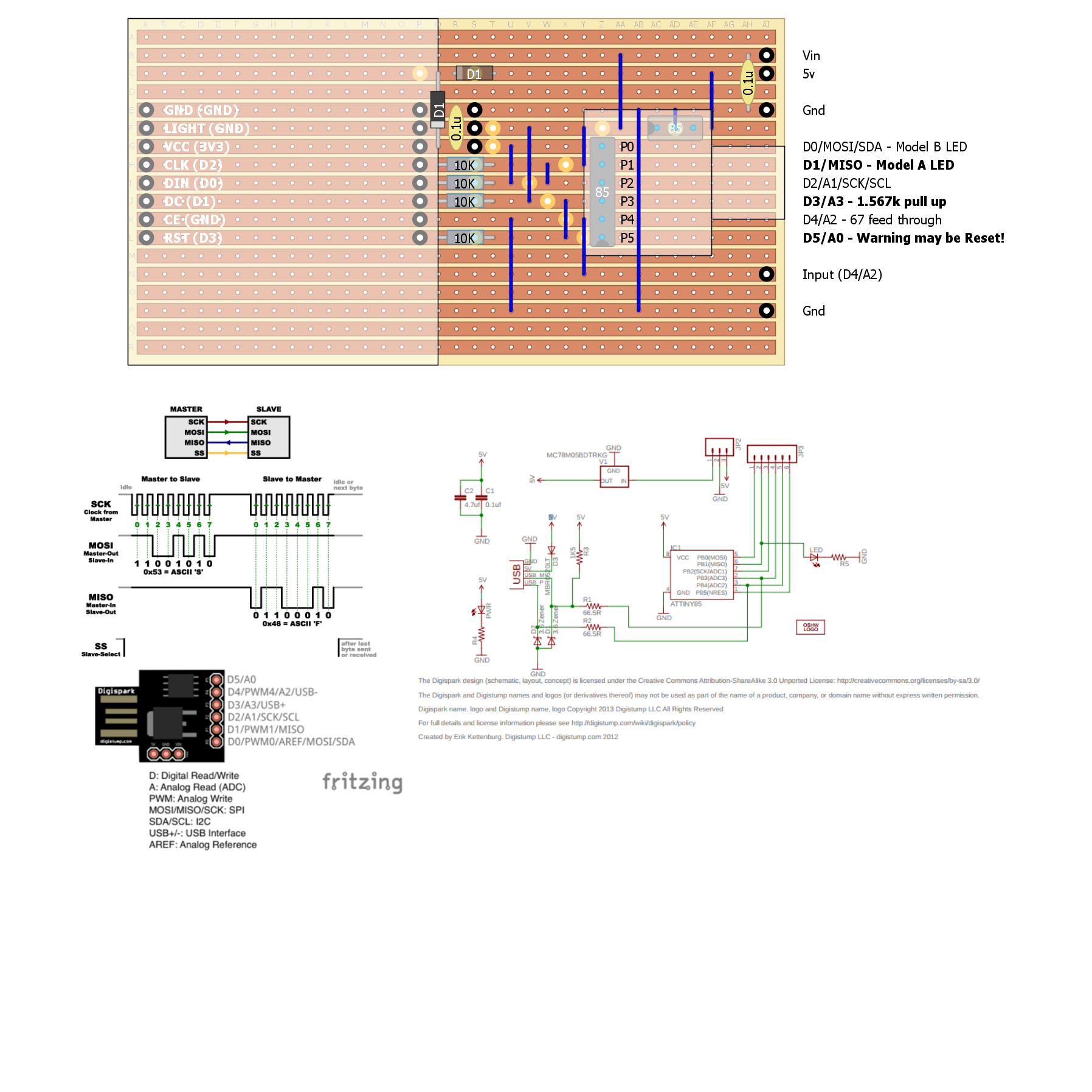
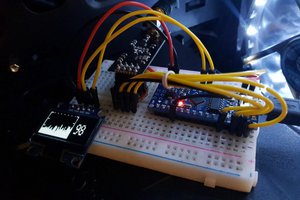
The next step is to port the code to a suitable Arduino board.

I have a number of DigiSpark (ATTiny85) boards and Nokia graphic displays.

So that is what I will likely use.

The ATTiny85 has an ADC sampling rate of 125 kHz.

A high ADC sampling rate is important.

AlanX

SpectrumAnalzerDigiSparkLCD.ino

This version for the DigiSpark.

ino - 9.00 kB - 10/27/2016 at 07:08

Download

SpectrumAnalzerNokiaLCD.ino

Latest version with sampleFrequency measurement fix.

ino - 5.27 kB - 10/25/2016 at 12:33

Download

SpectrumAnalzerMircoView.ino

Version for uView (not latest version)

- 4.47 kB - 10/25/2016 at 02:40

Download

  • Project Well Received

    agp.cooper12/04/2016 at 00:39 0 comments

    Project Well Received

    I am a little surprised that the project has done so well. But then who would not be interested in a "Spectrum Analyser". It sounds so geeky!

    In essence I had partially developed the code for another task and just saw the opportunity for a quick project.

    Project logs are a little hard for a novice to follow if they just want to build one, as a log is about the journey rather than the destination. Often just a sentence from someone else's journey is all you need to solve a problem with your project.

    So I thought I would post some step by step instructions (well not quite that detailed).

    Regards AlanX

  • DigiSpark Version

    agp.cooper10/27/2016 at 07:53 0 comments

    The DigiSpark (ATTiny85) Version

    Well that was the original idea concept.

    For the DigiSpark I had to write the LCD code as the DigiSpark does have enough memory for a "frame buffer" making "graphics" rather difficult (so no ready made libraries).

    There are lots of code examples on the internet (Jilian Ilett's site is very good one: https://www.youtube.com/watch?v=RAlZ1DHw03g&list=PLjzGSu1yGFjXWp5F4BPJg4ZJFbJcWeRzk).

    I used those examples but added the (very limited) graphics that I required.

    Here is the assembled project reading a 0-3v 1 kHz square wave:

    The DigiSpark CPU clock is about 16.5 MHz but the micros() statement appears to assume 16 MHz.

    I had to scale micros() by 16.9/16.0 to get the correct frequency response.

    Here is the adjusted display:

    So all done.


    Problems with the DigiSpark


    The DigiSpark I am using is a cheap clone and the fuses have not be set to allow the use of PB5, the Reset pin.

    Yes if you try to use as an input, it it will reset the DigiSpark, also it will not let you use it as an output.

    That is why I said previously the DigiSpark had only 5 IO pins.

    Well that can be fixed with a high voltage (12v) programmer so I should look into it if I use the DigiSpark more often.

    Also a Reset take 5 seconds to give the USB connection a chance before actually rebooting. That can be fixed as well (there is a no wait boot loader that checks the reset pin status first).

    Programming the DigiSpark Fuses

    I found this site that steps through the solution:

    http://thetoivonen.blogspot.my/2015/12/fixing-pin-p5-or-6-on-digispark-clones.html.


    Now I have a ATTiny85 programmer shield for the Arduino UNO so I checked the schematic (all good) and uploaded ArduinoISP.

    But if you don't have a sheild then you can just wire it up as per the web-site instructions.

    The only thing I did not do is add the Reset capacitor recommended by the web-site..


    Next I have XLoader that has AVRDude, so I put a batch file in the directory and ran it.

    Now AVRDude is also part of the Arduino IDE so you have a copy of AVRDude.


    All good the first time.

    Tested the DigiSpark and all good.

    Here is the batch file if you ever need it:

    Echo Read the signature should be: 0x1e930b
    Echo
    avrdude -P com5 -b 19200 -c avrisp -p attiny85 -n
    pause
    Echo 
    Echo Ready to write fuses? Kill window if not!
    pause
    avrdude -P com5 -b 19200 -p attiny85 -c avrisp  -U hfuse:w:0x5F:m
    pause

    AlanX

  • Nokia LCD Version

    agp.cooper10/25/2016 at 12:31 0 comments

    Nokia LCD Version

    I downloaded the Adafruit Nokia LCD Libraries.

    At 5v the LCD contrast was uncontrollable.

    Assuming the LCD would be 5v tolerant (really I should have put serial 10k resistors in the data lines) I just powered it with the 3v3 Arduino supply.

    It worked fine.

    If I wire the CE or CS line low then I only need 4 outputs from the Arduino but I have not told the library as of yet (i.e. have not worked out how to do it).

    Mostly a search and replace of "uView" for "display" but there were differences.

    As the Nokia display is an extra 20 pixels wide I increased the data area width from 41 pixels to 61 pixels.

    Here is the Nokia working with the 0-3v 1 kHz square wave signal:

    The frequency does seem to be a little off (~5%)? Fixed it by timing every sample run:

    Speed Test

    For the above test:

    • Sample frequency: 62437 Hz
    • Nominal bandwidth: 500 Hz
    • Number of samples: 249
    • Maximum frequency: 6000 Hz
    • Frequency bins: 61
    • Noise floor <-30 dB
    • Cycle time 760 ms

    At 760 ms this is about as a much as this algorithm can do!

    If I want more I will have to migrate to DFT.

    AlanX

  • Graphics

    agp.cooper10/24/2016 at 00:31 2 comments

    Nokia LCD Display

    I have a few of these lying around and I wrote some code using a DigiSpark a while back. The code is based on work by Julian Ilett (https://www.youtube.com/playlist?list=PLjzGSu1yGFjXWp5F4BPJg4ZJFbJcWeRzk).

    First problem is that the display needs 5 output pins and the DigiSparks only has five IO pins so that is not going to work (i.e. no pin left for the signal input).

    I could use an Arduino UNO with the Nokia LCD Display.

    MicroView

    I have a MicroView so I may as well use that.

    So here it is listening to a 3v 1kHz square wave:

    The top gradations are 0 kHz, 1.25 kHz, 2.5 kHz, 3.75 kHz and 5 kHz.

    You can see the DC, 1 kHz and the harmonics but they off a little bit.

    Next there is quite a bit of jitter at low frequencies, here is another shot:

    The 1 kHz and DC signals have merged.

    Here is the same square wave but with a 20kHz:

    Improvements

    Need to check the actual average sample time for each pass.

    Need understand the nature of the jitter.

    Is it an interrupt or is it due to the algorithm?

    Need some free IO pins for an option menu (after I solve the other problems).

    Here is the current code:

    #include <MicroView.h>
    
    // Audio Spectrum Analyser
    #define SampleInput A0   // Name the sample input pin
    #define BandWidth  500   // BandWidth
    #define MaxFreq   4000   // Max analysis frequency
    #define Trigger     10   // Trigger to synchronise the sampler 2vpp at 1kHz = 32
    
    // Define various ADC prescaler
    const unsigned char PS_16=(1<<ADPS2);
    const unsigned char PS_32=(1<<ADPS2)|(1<<ADPS0);
    const unsigned char PS_64=(1<<ADPS2)|(1<<ADPS1);
    const unsigned char PS_128=(1<<ADPS2)|(1<<ADPS1)|(1<<ADPS0);
    
    // Setup the serial port and pin 2
    void setup() {
      // Setup the ADC
      pinMode(SampleInput,INPUT);
      ADCSRA&=~PS_128;  // Remove bits set by Arduino library
      // Set prescaler 
      // ADCSRA|=PS_64; // 64 prescaler (250 kHz assuming a 16MHz clock)
      // ADCSRA|=PS_32; // 32 prescaler (500 kHz assuming a 16MHz clock)
      ADCSRA|=PS_16;    // 16 prescaler (1 MHz assuming a 16MHz clock)
    
      uView.begin();                          // Start MicroView
      uView.clear(PAGE);                      // Clear page
      uView.println("Spectrum  Analyser");    // Project
      uView.println("0-20 kHz");              // Range
      uView.println();
      uView.println("agp.cooper@gmail.com");  // Author
      uView.display();                        // Display
      uView.clear(PAGE);                      // Clear page
      delay(2000);                            // Wait
    }
    
    void loop() {  
      static byte *samples;           // Sample array pointer
      static byte *window;            // Window array pointer
      static int N=0;                 // Number of samples for BandWidth
      static long sampleFreq;         // Sample frequency     
      long freq;                      // Frequency of interest
      float s;                        // Goertzel variables
      float s_prev;
      float s_prev2;
      float coeff;
      float magn;
      int i;
    
      if (N==0) {
        // Check sample frequency and set number of samples
        samples=(byte *)malloc(100);
        unsigned long ts=micros();
        for (i=0;i<100;i++) samples[i]=(byte)(analogRead(SampleInput)>>2);
        unsigned long tf=micros();
        free(samples);
        sampleFreq=100000000/(tf-ts);
        N=2*sampleFreq/BandWidth+1;
        
        uView.setCursor(0,0);                   // Set cursor to beginning
        uView.print("SI: A");                   // Sample input pin 
        uView.println(SampleInput-14);
        uView.print("SF: ");                    // Sample frequency 
        uView.println(sampleFreq);
        uView.print("MF: ");                    // Max frequency 
        uView.println(MaxFreq);
        uView.print("BW: ");                    // andWidth
        uView.println(MaxFreq);
        uView.print("SN: ");                    // Number of samples
        uView.println(N);
        uView.display();                        // Display
        uView.clear(PAGE);                      // Clear page
        delay(2000);
        
        // Create arrays
        samples=(byte *)malloc(N);
        window=(byte *)malloc(N);
     
        // Modified Hamming Window
        for (i=0;i<N;i++) window[i]=(byte)((0.54-0.46*cos(2*M_PI*i/(N-1)))*255); 
    
        // Generate test samples
        for (i=0;i<N;i++) {
          samples[i]=(byte)(30*(sin(2*M_PI*i*5000/sampleFreq)+sin(2*M_PI*i*2500/sampleFreq)+sin(2*M_PI*i*7500/sampleFreq)+sin(2*M_PI*i*10000/sampleFreq))+127);
        }
      }
    
      if (true) {
        // Sychronise the start of sampling with data slicer
        int a0,a1;
        a0=1023;
        for (i=0;i<N;i+=2) {    
          a1=analogRead(SampleInput);
          a0=(a0*13+a1*3)/16;
          if (a1>a0+3) break;
        }
        for (i=0;i<N;i++) samples[i]=(byte)(analogRead(SampleInput)>>...
    Read more »

  • Arduino Code for Spectrum Analyzer - No Graphics

    agp.cooper10/23/2016 at 14:20 2 comments

    Arduino Code for Spectrum Analyzer

    As the DigiSpark has no (working!) serial communications and the ADC for the Arduino UNO is the same for the ATTiny85 (I think), I have prototyped the code for an Arduino UNO. So all done except for the graphics!

    Here is the code:

    // Audio Spectrum Analyser
    #define N 100            // Number of samples
    #define SampleFreq 50000 // Average free running speed 
    byte samples[N];         // Sample array
    byte window[N];          // Window array
    
    
    // Define various ADC prescaler
    const unsigned char PS_16 = (1 << ADPS2);
    const unsigned char PS_32 = (1 << ADPS2) | (1 << ADPS0);
    const unsigned char PS_64 = (1 << ADPS2) | (1 << ADPS1);
    const unsigned char PS_128 = (1 << ADPS2) | (1 << ADPS1) | (1 << ADPS0);
    
    // Setup the serial port and pin 2
    void setup() {
      int i;
    
      pinMode(LED_BUILTIN,OUTPUT);
      digitalWrite(LED_BUILTIN,LOW);
      
      // Setup the ADC
      pinMode(A2, INPUT);
      ADCSRA &= ~PS_128;  // remove bits set by Arduino library
      // Set prescaler 
      // ADCSRA |= PS_64; // 64 prescaler (250 kHz assuming a 16MHz clock)
      // ADCSRA |= PS_32; // 32 prescaler (500 kHz assuming a 16MHz clock)
      ADCSRA |= PS_16;    // 16 prescaler (1 MHz assuming a 16MHz clock)
    
      // Hamming Window
      for (i=0;i<N;i++) window[i]=(byte)((0.54-0.46*cos(2*M_PI*i/(N-1)))*255); 
      // Generate test samples
      for (i=0;i<N;i++) samples[i]=(byte)(50*sin(2*M_PI*i*4000/SampleFreq)+50*sin(2*M_PI*i*7000/SampleFreq)+127);
    
      Serial.begin(9600);
      Serial.println();
    }
    
    
    void loop() {  
      int i;
      int freq;
      float s;
      float s_prev;
      float s_prev2;
      float coeff;
      float magn;
    
      if (false) {
        // Capture the values to memory
        for (i=0;i<100;i++) samples[i]=(byte)(analogRead(A2)>>2);
      } else {
        // Pretend to be working
        delay(N*1000/SampleFreq);
      }
      
      // Scan frequencies
      for (freq=0;freq<=20000;freq+=1000) {
        coeff=2*cos(2*M_PI*freq/SampleFreq);
        s_prev=0;
        s_prev2=0;
        for (i=0;i<N;i++) {
          // Goertzel
          s=0.0000768935*window[i]*samples[i]+s_prev*coeff-s_prev2;
          s_prev2=s_prev;
          s_prev=s;
        }
    
        // Get magnitude
        magn=2*sqrt(s_prev2*s_prev2+s_prev*s_prev-coeff*s_prev*s_prev2)/N;
    
        Serial.print("Freq: ");
        Serial.print(freq);
        Serial.print(" Magn: ");
        Serial.println(magn);
      }
      digitalWrite(LED_BUILTIN,!digitalRead(LED_BUILTIN));
      delay(1000);
    }


    Here is the output:

    1. Freq: 0 Magn: 2.67
    2. Freq: 1000 Magn: 0.00
    3. Freq: 2000 Magn: 0.00
    4. Freq: 3000 Magn: 0.00
    5. Freq: 4000 Magn: 0.53
    6. Freq: 5000 Magn: 0.00
    7. Freq: 6000 Magn: 0.00
    8. Freq: 7000 Magn: 0.53
    9. Freq: 8000 Magn: 0.00
    10. Freq: 9000 Magn: 0.00
    11. Freq: 10000 Magn: 0.00
    12. Freq: 11000 Magn: 0.00
    13. Freq: 12000 Magn: 0.00
    14. Freq: 13000 Magn: 0.00
    15. Freq: 14000 Magn: 0.00
    16. Freq: 15000 Magn: 0.00
    17. Freq: 16000 Magn: 0.00
    18. Freq: 17000 Magn: 0.00
    19. Freq: 18000 Magn: 0.00
    20. Freq: 19000 Magn: 0.00
    21. Freq: 20000 Magn: 0.00

    Which is correct!

    Note that the magnitude calculation is not 100% accurate.

    The DC component should be 2.49v rms (not 2.67) and the two frequencies (4000 Hz and 7000 Hz) should be 0.5v rms (not 0.53). The error issue is understood to be due to "phase" errors and "Window" errors.

    Execution time:

    • sampling 2.0 ms
    • calculation per frequency 1.2 ms
    • Total time (21 frequencies) 27 ms

    So all good!

    AlanX

  • An Integer Version of Goertzel Algorithm

    agp.cooper10/23/2016 at 10:25 2 comments

    ATTiny85 Migration

    Migrating the test code to ATTiny85 requires some optimisation to suit the limitations of the processor program, RAM and execution speed.

    The ATTiny85 has;

    • 512 bytes of SRAM
    • 8k bytes of EEPROM
    • ADC conversion time (10 bits ~125 kHz) but can be clocked higher (~1 MHz) for less accuracy.

    SRAM will be the main limitation.

    *** Big mistake ***

    The 125 kHz specification is the ADC clock speed, not the conversion speed.

    It takes 25 cycles for the first conversion and then 13 cycles per conversion.

    This is 9.6 kHz!

    All is not lost, I can speed (http://www.microsmart.co.za/technical/2014/03/01/advanced-arduino-adc/) clocked his code on an AVR at an average of 20.5 us (48.8 kHz).

    Not enough for a 40 kHz ultrasonic tone converter but enough for an audio spectrum analyzer.

    Integer Goertzel

    Can I avoid floating point maths?

    My first attempt a while back failed.

    I did not really try to work it out then.

    This time I set up variable shift fixed point maths.

    Using long (32 bit) failed for low frequencies (i.e. 100 Hz).

    Using long long (64 bit) worked for shifts between 15 and 20:

    Integer Goertzel Numerical Stability
    Frequency 100 Hz
    Data Type Magnitude Error
    Single 105.0406 0.001%
    Double 105.0415 0.000%
    Long long fixed point Shift
    13 92.559 11.883%
    14 100.272 4.541%
    15 104.327 0.680%
    16 104.329 0.678%
    17 104.329 0.678%
    18 104.846 0.186%
    19 104.846 0.186%
    20 104.976 0.062%
    21 121.582 -15.747%
    22 108.954 -3.725%

    Single precision (float) work okay as well.

    As long long takes as long as float to process there is no advantage to using integers for this algorithm!

    If you are wondering what variable shift fixed point code looks like, here is the critical bit of code:

        coeff=(long long)(2*cos(2*M_PI*freq/SampleFreq)*(1<<shift));
        s_prev=0;
        s_prev2=0;
        for (i=0;i<N;i++) {
          // Goertzel
          s=(window[i]*samples[i]>>shift)+(s_prev*coeff>>shift)-s_prev2;
          s_prev2=s_prev;
          s_prev=s;
        }
    

    Yes, all you do is scale everything up before use, using "*(1<<shift)" and scale any multiplications down using ">>shift".

    AlanX

View all 6 project logs

  • 1
    Step 1

    A Simple Spectrum Analyser

    What you will need

    • A multimeter (better with a logic probe)
    • A single generator (1 kHz square wave generator)
    • A soldering station and accessories (solder, desoldering wick etc.)
    • A Digispark microprocessor board and USB connection cable)
    • An Arduino Development Environment (with the Digispark driveres and libraries installed).
    • A Nokia LCD display
    • 4x 10k resistors.
    • 2x 0.1uF decoupling capacitors
    • 2x 1n4148 diodes
    • A strip of pin headers
    • A length of hookup wire (0.6 mm tinned solid copper wire).
    • A two pin shunt (it shorts out two pins)
    • A piece of strip-board (~45mm x 90mm)
  • 2
    Step 2

    Preparing the Digispark and Arduino IDE

    The Digispark is not the easiest Arduino development board to use. There is a custom version of the Arduino IDE you can use but it is old (version 1.06!). Better to bite the bullet and use the latest Arduino IDE version and install the drivers and libraries. Search for Digispark drivers or just go to: https://digistump.com/wiki/digispark/tutorials/connecting. Not everything on this site is current so you experience may differ. You can get the Win10 drivers from: https://github.com/digistump/DigistumpArduino/releases/download/1.6.7/Digistump.Drivers.zip.

    You may need to disable windows driver signage to install the drivers (I have driver signage off by default so I am not sure if the drivers are signed or not).

    Windows may not recognise your Digispark! If so try using a USB 2 port (rather than a USB 3 port) or routing through a USB hub (best option).

    Also note that the Digispark is only connected to your PC when uploading a file and when asked to by the uploading software. It is not like an ARduino UNO or Nano.

    Once you have set up the software test which Digispark version you have (Model A or Model B).

    Be patient it does work!

    Problems with Cheap Digispark Clones

    The cheap Digispark clones usually don't have PB5 or A0/D5 (the reset pin) turned on. You can test this by tring to use PB5 (D5) as an output (try toggling an LED).

    Although last version of the Spectrum Analyser published has this fault, it would be much more useful if the "fuses" are set to activate PB5.

    To do so download XLoader (http://xloader.russemotto.com/). Add the following batch file to the directory:

    Echo Read the signature should be: 0x1e930b
    Echo
    avrdude -P com5 -b 19200 -c avrisp -p attiny85 -n
    pause
    Echo 
    Echo Ready to write fuses? Kill window if not!
    pause
    avrdude -P com5 -b 19200 -p attiny85 -c avrisp  -U hfuse:w:0x5F:m
    pause

    Notes:

    • "com5" will need to be edited for you PC/Digispark port!
    • When you run the batch file, check that the reported signatures match before proceeding!
  • 3
    Step 3

    Schematic

    Here is my strip-layout for the version that I built:

    Notes:

    • The three inline black circles (pins) above the resistors are for the two pin shunt. Short the upper pins and the LCD lights up. Short the lower pins and the LCD does not light.
    • The project can use power from the PC via the USB port and/or power from the Vin or 5v pins.
    • If you set the PB5 fuses you can use D5/A0.
    • I have folded the ground pin of the Digispark in order to fit it to the strip-board.
    • Finally the Digispark is elevated about 0.1" so that the USB plug will fit between the strip-board and the Digispark USB plug!

View all 4 instructions

Enjoy this project?

Share

Discussions

agp.cooper wrote 12/04/2016 at 00:29 point

Hi Elliot,

I told my partner that someone thought my Spectrum Analyser was sexy!

She was horrified and responded "another madman".

Regards AlanX 

  Are you sure? yes | no

Elliot Williams wrote 11/28/2016 at 17:11 point

Man, that's sexy!

  Are you sure? yes | no

agp.cooper wrote 10/24/2016 at 10:06 point

Hi All,

I have fixed various issues (jitter being the main one) and it is working within reasonable expectations (no doubt better ways to do things will be found and a bug or two still lives in the code).
However until I have an application to put this project to work, I will call it complete.

Regards AlanX

  Are you sure? yes | no

K.C. Lee wrote 10/24/2016 at 15:53 point

Saw the new display.  Nice.

  Are you sure? yes | no

agp.cooper wrote 10/24/2016 at 23:53 point

Hi Lee,

Thanks my camera does not work too well at night so it is a little blurry.

The main problem with the microView is that it is so small! With my eyesight I can hardly see it.

I suspect the display controller will be Nokia LCD compatible (have to check) so I will migrate to an UNO and Nokia LCD to see, else find a Nokia LCD library. 

Trigger Logic

To remove phase jitter I trigger the start of the sampling on the falling edge of the signal (i..e. sychronise the sampling to the signal) using a differentiator. That works with the test square wave but less than ideal for general use. It should trigger on a 0.3v 1 kHz sine wave OR high frequency noise! But for general use low frequency flicker is not really a problem 

Last night I though about using a data slicer (a low pass filter and a comparator). This should be more robust.

Do you know what other people use to minimise phase jitter at low frequencies?

AlanX 

  Are you sure? yes | no

K.C. Lee wrote 10/25/2016 at 00:08 point

I am using timing from the microcontroller for the sampling.  There are no external synchronization needed.  I played with different windowing functions.  I would assume that internal RC on the Attiny would add a small amount of jitter vs a crystal. 

Nokia LCD is pretty simple and I wrote my own library to take advantage of DMA SPI.  I tied the /Reset to the uC's reset to save 1 I/O line, so only needing 4 I/O.

  Are you sure? yes | no

David H Haffner Sr wrote 10/24/2016 at 08:27 point

This is very...Very interesting!

  Are you sure? yes | no

agp.cooper wrote 10/24/2016 at 03:51 point

Lee/Eric,

It works but I get low frequency jitter or flicker.

With high impedance input (i.e. no input) I get lots of DC noise (flickering from 0 to 3v rms).

With a 1 kHz 0-3v square wave I get flicker on the DC and low frequencies (see my last post).

Is this a software problem (phase noise etc.) or

a sampling problem (inconsistent sampling periods and/or interruption to sampling) or

something else?

I am thinking I should use a timer and an ISR for the sampling routine.

Regards AlanX 

  Are you sure? yes | no

K.C. Lee wrote 10/24/2016 at 04:31 point

I have a few dB of noise (1-2 pixels on my scale) at the low frequency when there are no inputs. DC can be fluctuate a bit due to the way I calculate DC offset.  I don't try to display 0Hz on my display as there are no useful info for my application.

Both of them uses timer to trigger ADC conversion directly in hardware and results are stored in buffer via DMA.  Those are the perks of using ARM chips.

Jitters in triggering ADC in general would result in low frequency noise.

Also both of them uses DC coupling on the input stage and carefully placed RC anti-alias filters located very closed to the ADC input pins.  The DC offset is done via software summing over blocks of samples and subtracted prior to DFT.

My initial prototype on a breadboard runs into layout related noise issue.  The PCB resolved the noise issues.

There are the projects that use spectrum analyzer.  The first one is a finished project while 2nd one has more current code for graphics.

https://hackaday.io/project/12133-automatic-audio-source-switchinghttps://hackaday.io/project/12703-alarm-detection-for-hearing-impaired

All my source files are on github:

https://github.com/FPGA-Computer/Automatic-Audio-Switch
https://github.com/FPGA-Computer/Alarm-Detection

Here is a frequency sweep using my sound card on my PC: sine wave from 20Hz to 19.2kHz


Notice the noise showing up on the left side as 1-2 pixels tall.  ALso see the effect of anti-alias low pass filter - the amplitude decreases slightly as the frequency increases.  Freq resolution is 300Hz bins plotted as 1 pixel wide and amplitude is plotted in dB.

  Are you sure? yes | no

agp.cooper wrote 10/24/2016 at 04:57 point

Hi Lee,

I found two issues

-

Sample Frequency:

The sample frequency was off, I was getting 64.4 kHz with the microView and 48.8 kHz with an old Aurduino UNO (basically chip differences!).

So I now measure the sample frequency in setup.

-

The second issue as phase error:

If I wait for a high to low transition before sampling then most of the low frequency flicker is gone.

Flicker is about 1 or 2 pixels.

-

So all good.

AlanX

  Are you sure? yes | no

agp.cooper wrote 10/24/2016 at 05:18 point

Hi Lee,

Cool! I need a gif animator too.

Here is my jitter free version of a 3v 1 kHz square wave (ticks are 1 kHz apart):


Regards AlanX

  Are you sure? yes | no

agp.cooper wrote 10/23/2016 at 09:47 point

Hi Eric/Lee,

Thanks Eric for your integer version of Goertzel's algorithm.

-

I recoded my double precision for long (32 bit) fixed point with a variable shift.

It partially works, it fails at low frequencies (i.e. 100 Hz).

Reworked for "long long" (64 bit) and it works for shifts between 15 and 20.

Accuracy is within 0.2% for shifts of 18, 19 and 20.

As "long long" takes as long (longer!) as a float to execute, there is no advantage to using integers with this algorithm!

-

Float works okay as well (0.001% error).

-

Regards AlanX

  Are you sure? yes | no

K.C. Lee wrote 10/23/2016 at 13:54 point

If the output is for Nokia 5110 LCD, then you would only have 48 vertical pixels to plot (each pixel is +/-2%).  The vertical axis is usually in log scale.  (I'll let someone works out the tolerances for that)  Not sure if you need that level of precision.

Elm-chan has optimized fixed point DFT library (written in assembly) for MegaAVR 
http://elm-chan.org/works/akilcd/report_e.html

He also have C code for ARM in a different project which is what I am using on the STM32F03 for real time FFT.

  Are you sure? yes | no

agp.cooper wrote 10/23/2016 at 14:48 point

Hi Lee,

Thanks but I will play with this for a while.

In many respects my project is just a toy so not that fussed about accuracy and speed etc.

48 pixels width is just about right for 0 to 20 kHz, the sampling frequency is only 50 kHz.

I just posted some code and results (using an Arduino UNO).

Pretty happy with that. Just the graphics and a box to go.

Regards AlanX

  Are you sure? yes | no

agp.cooper wrote 10/23/2016 at 03:38 point

Hi Lee,

Hamming Window:

Yes you are right, I moved the Hamming Window code outside of the main loop.

The code was a test of the algorithm rather than any attempt at optimisation (for the ATTiny85).

-

DFT vs Goertzel:

Yes you are right DFT is faster. The main reason for this approach is the simplicity of the code.

A long time ago (20 years ago?), I wrote a terminal program that used a QuickCam to send images over a modem/telephone line concurrent to typing. That code used a DFT to compress the image (primative JPEG). So I can write the DFT code if I have no choice.

I will have to see how far I can push the ATTiny85 with regards to the number of frequencies steps, number of samples etc.

-

Integer version of Goertzel:

I have looked but have not found an integer version of Goertzel.

I did play around playing with integers but the algorithm is a bit tricky (trying to avoid divides).

Did you have a reference for an integer version of Goertzel algorithm?

-

Regards AlanX

  Are you sure? yes | no

Eric Hertz wrote 10/23/2016 at 04:26 point

Wow, I haven't heard of anyone's even having heard of the Goertzel algorithm for quite some time! But, am a bit confused, isn't Goertzel supposed to be for detecting a *single* frequency? Isn't that why it's supposed to be so much faster than FFT, etc.?

If you're interested, I've thrown up my integer-based Goertzel code in the "files" section at #commonCode (not exclusively for AVRs)... but take it with a tiny grain of salt, as it's been years, and I honestly don't remember whether it even works.

  Are you sure? yes | no

agp.cooper wrote 10/23/2016 at 06:38 point

Hi Eric,

The code was originally written for an ultrasonic sensor.

Yes Goertzel is a single frequency but nothing is stopping you from repeating the calculations for lots of frequencies.

It is slow than DFT as the multi-frequency version has a square law execution time (O=n^2) while DFT is probably  O=nlogn.

I will have a look at your integer version.

Regards AlanX

  Are you sure? yes | no

Eric Hertz wrote 10/23/2016 at 15:28 point

Oh lordy, don't anybody look at my goertzel-code... that thing's a mess. Sorry agp.cooper, if you were blinded by it!

  Are you sure? yes | no

K.C. Lee wrote 10/23/2016 at 02:01 point

The hamming window terms can be precomputed as constants they are always the same.  ADC input is integer, so you can use integer DFT (or integer Goertzel) which speed up things a lot.  If you are  plotting data, remember that pixels are integers.

ATTINY85 has only 512-Byte SRAM which limits the size of FFT as you'll need to store the ADC data, intermediate and results.  Using floating point increased the storage requirement vs 16-bit integer.

FYI: 256-point FFT is what I can do in 4K RAM inside my STM32F030.

  Are you sure? yes | no

Similar Projects

Does this project spark your interest?

Become a member to follow this project and never miss any updates