John Opsahl
-
automated brush cleaning
07/21/2019 at 16:55 • 0 commentsCurrently, the cnc painter uses the same brush cleaning technique that human canvas painters use. Swirl the brush around in a cup of water and wipe it off on a paper towel. This procedure is performed at the start of any painting operation to ensure that the brush bristles are wet enough to accept paint, periodically during the painting process to prevent paint from drying on the brush, between paint colors, and at the end of the painting to clean the paint off the brush in preparation for storage. I would classify this technique as semi-autonomous. You don't have to physically clean the brushes yourself, but you do have to replace the water and paper towel periodically during operation. This technique has worked great so far, but has a few downsides -> the paper towel takes up a large percentage of the workspace (leaving less space for the canvas) and different brush sizes and types require unique water swirling and towel wiping patterns to effectively clean the paint of the brush.
I tried to come up with a universal mechanical solution. It involved rotating a brush while spraying it with powerful jets of water. I bought a small 12Vdc pump and designed a 3D printed nozzle that would direct two streams of water (90 degrees apart) at the same location. In order to avoid changing water as often, the water used to clean the brushes would be recirculated and a large volume of water would be used to dilute the paint that was washed off the brushes. It turned out working quite well for a variety of brush sizes and types. The water jets were strong enough to deflect the bristles and clean the center of the brush. The only additional design consideration would be to make an enclosure for it. Some of the water was splashing into my face.
Still looking around for more options I purchased a cheap ultrasonic cleaner bath. Even after one minute there was usually still a little bit of paint left on most brushes. It also gave me a headache if I left it on too long with the lid open.
Thinking the inverse of the ultrasonic cleaner may be more effective (vibrating the brush instead of the water), I bought a sonicare toothbrush next. It did about as well if not a little worse than the ultrasonic cleaner bath.
I decided that it was enough of a victory to have found a couple of viable solutions and would worry about how to integrate one of them later. The water swirl and towel wipe technique worked "good enough" at this point and I had bigger challenges to solve with this cnc painter. -
automated tool change
07/21/2019 at 04:31 • 0 commentsA tool change system was part of the requirements from the start of this project. Being able to use multiple tools like brushes, palette knifes, pens, markers, and pencils unlocks so many creative possibilities.
I tried to take inspiration from other cnc automated tool change mechanisms but most are overkill for this application. Most cnc machines that use tool changes need an end effector connection to withstand the high torques and forces experienced during milling. In contrast, end effector connections for cnc painting only need a to withstand the small torques and forces between paint filled brush bristles and a canvas. Ultimately though, it was the cost and large space requirements of existing tool change systems that sent me down the path of developing something new.
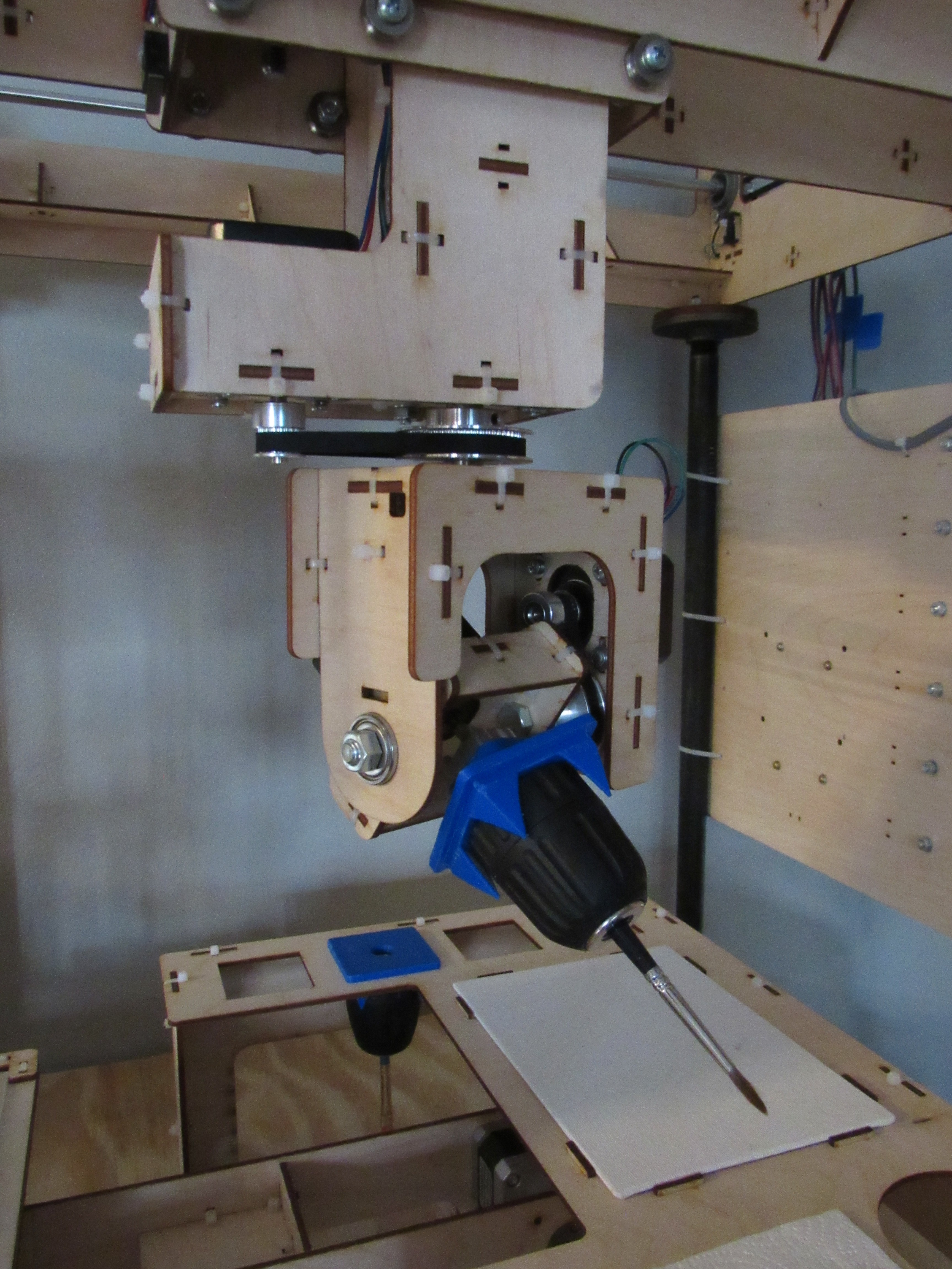
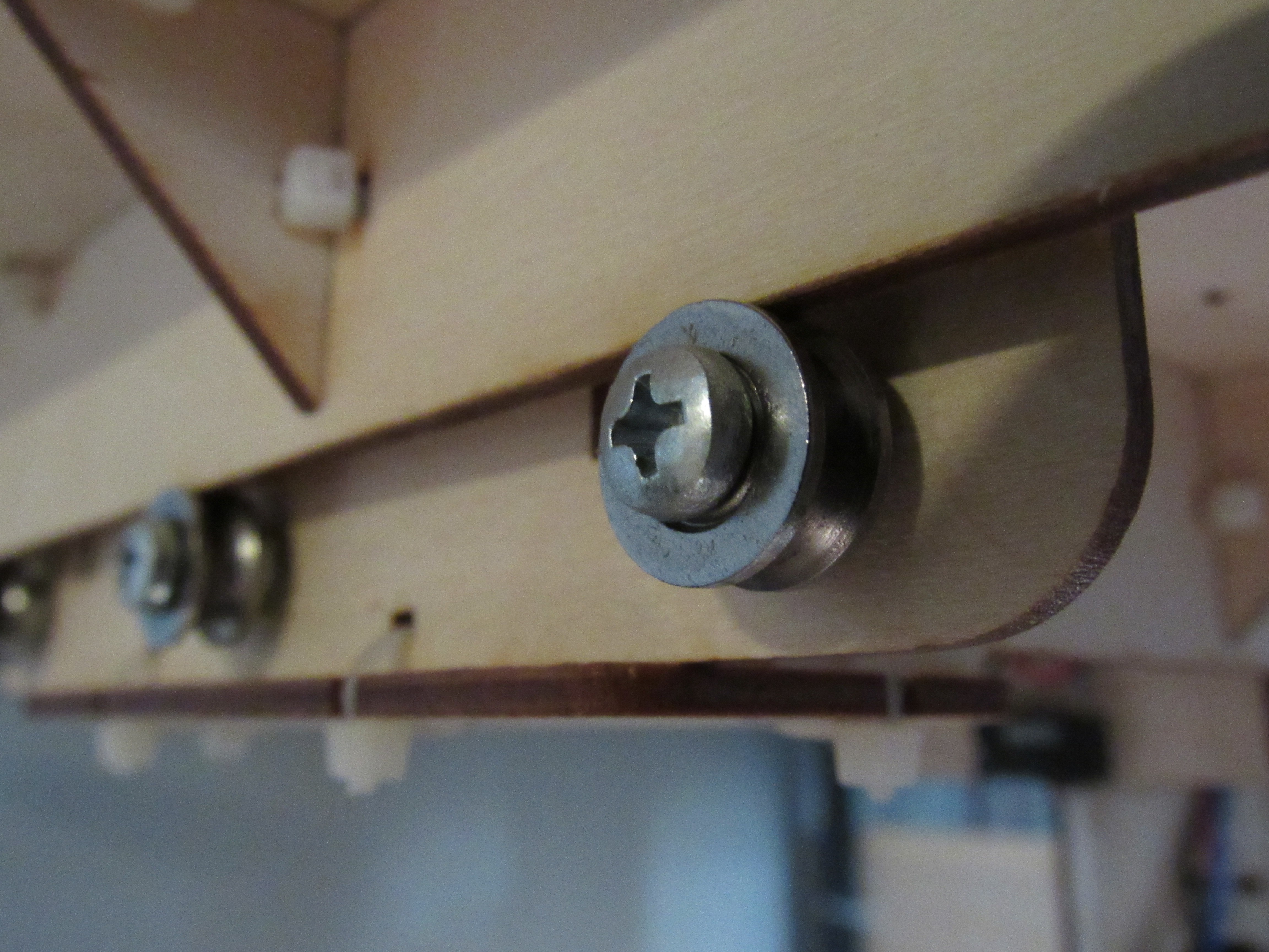
I settled on a simple screw-in design. Drill chucks are used to accommodate tool handle diameters up to 0.375in. A 3D printed part is fastened to the top of each drill chuck to assist with locating the tool into the tool docks on the workspace. Four tool docks are available on the workspace next to the canvas. Each drill chuck assembly has a 3/8-24 threaded hole on the top. A 3/8-24 bolt is secured to the C axis (aka sixth axis). To pick up a tool, the machine simply screws the C axis bolt into the threaded hole on one of the drill chuck assemblies. The C axis is commanded to turn and screw into the drill chuck assembly until the head of the screw contacts the drill chuck assembly and the C axis stepper motor overtorques. At which point, the C axis is set to zero in software. This same process is reversed for returning a tool to a dock.
On the topic of tool holders, I open sourced two laser cut artist tool chuck designs that can be used to retrofit a three axis cnc mill for cnc art: https://mega.nz/#F!Tc9w1DCI!gCbwh5lii0nDh_tOyw0b2g
![]()
![]()
-
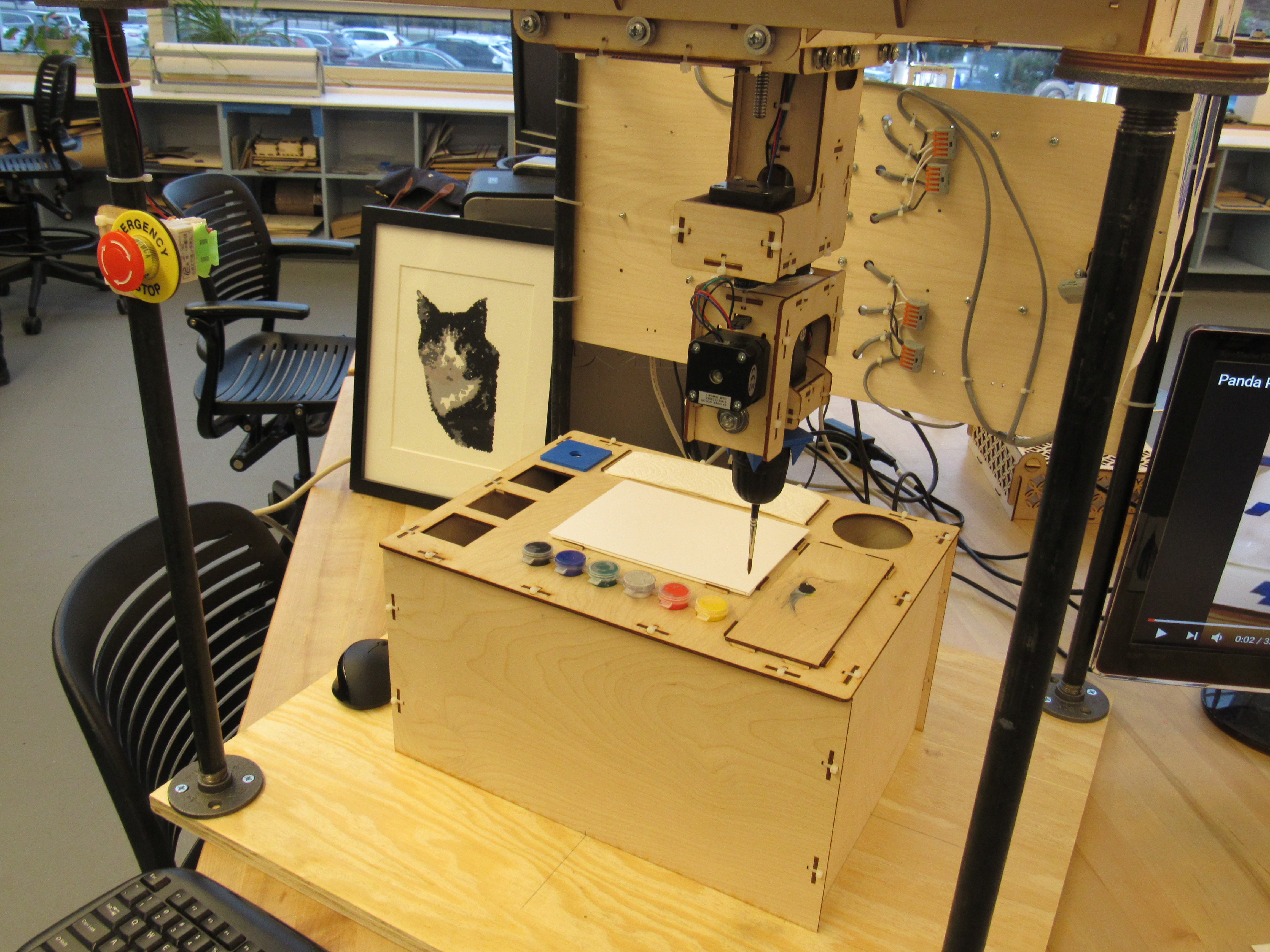
first paintings
07/20/2019 at 22:03 • 0 commentsIn October of 2018, I showcased the painter at a local library fundraiser. Committing to the event gave me the motivation to finalize the algorithm and start my first paintings. The response and feedback from the event was very positive and enthusiastic. Small crowds of event attendees stood around to watch it paint four quick paintings that I had put together for the event. One attendee commented that watching it paint was like the calming effect of staring into a camp fire.
![]()
![]()
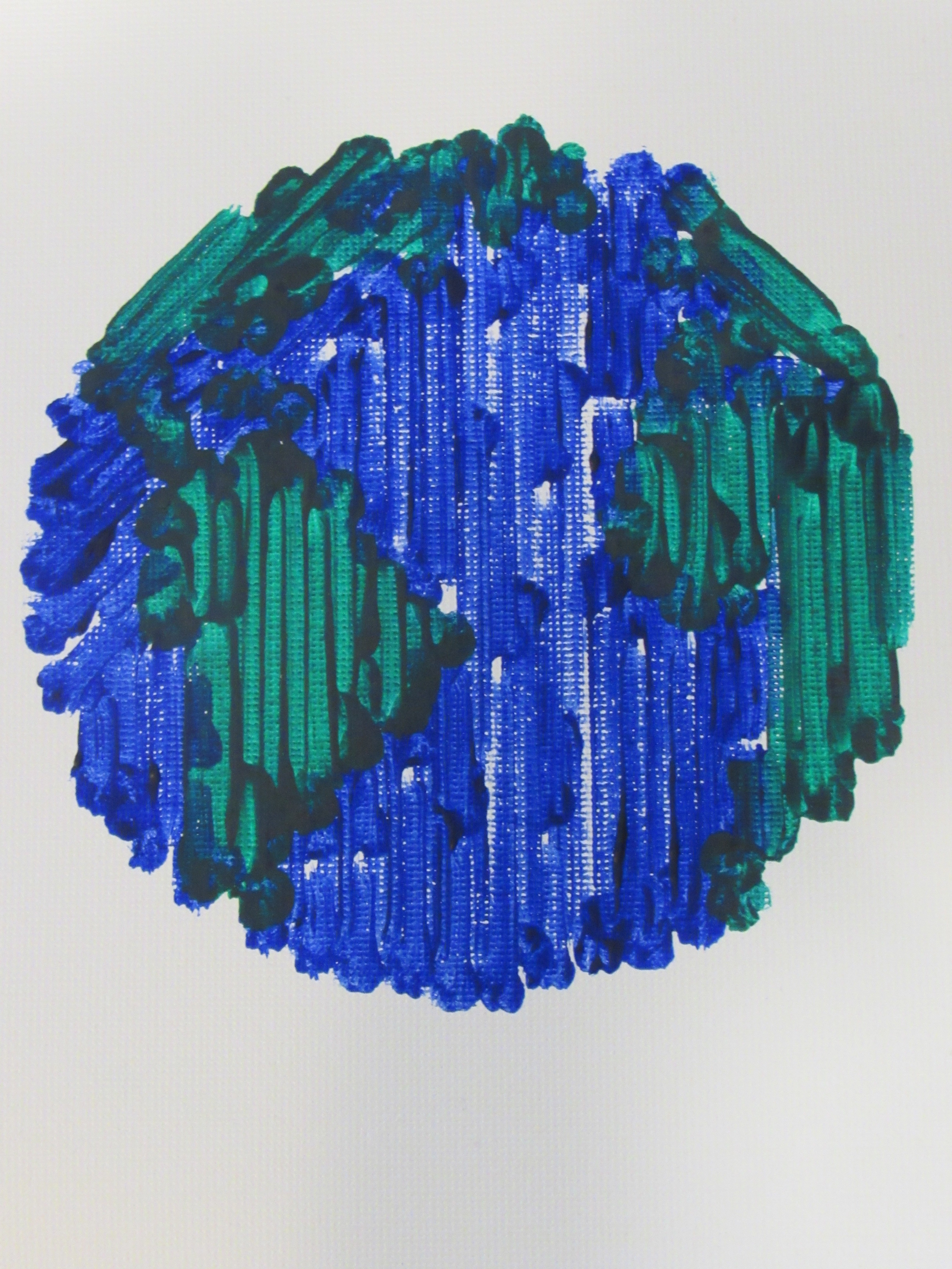
Because one the main reasons I was attempting this project was to become a better programmer, I thought it would be fun to stay true to the classic "Hello World" initiation. I decided that my first painting with this machine would be planet Earth. I probably painted ten of them before finalizing the painting settings (number of axes, brush type and size, distance brush can travel on canvas before going back for more paint, etc.). From an aesthetic point of view it's not my favorite painting but hey you have to start somewhere.
![]()
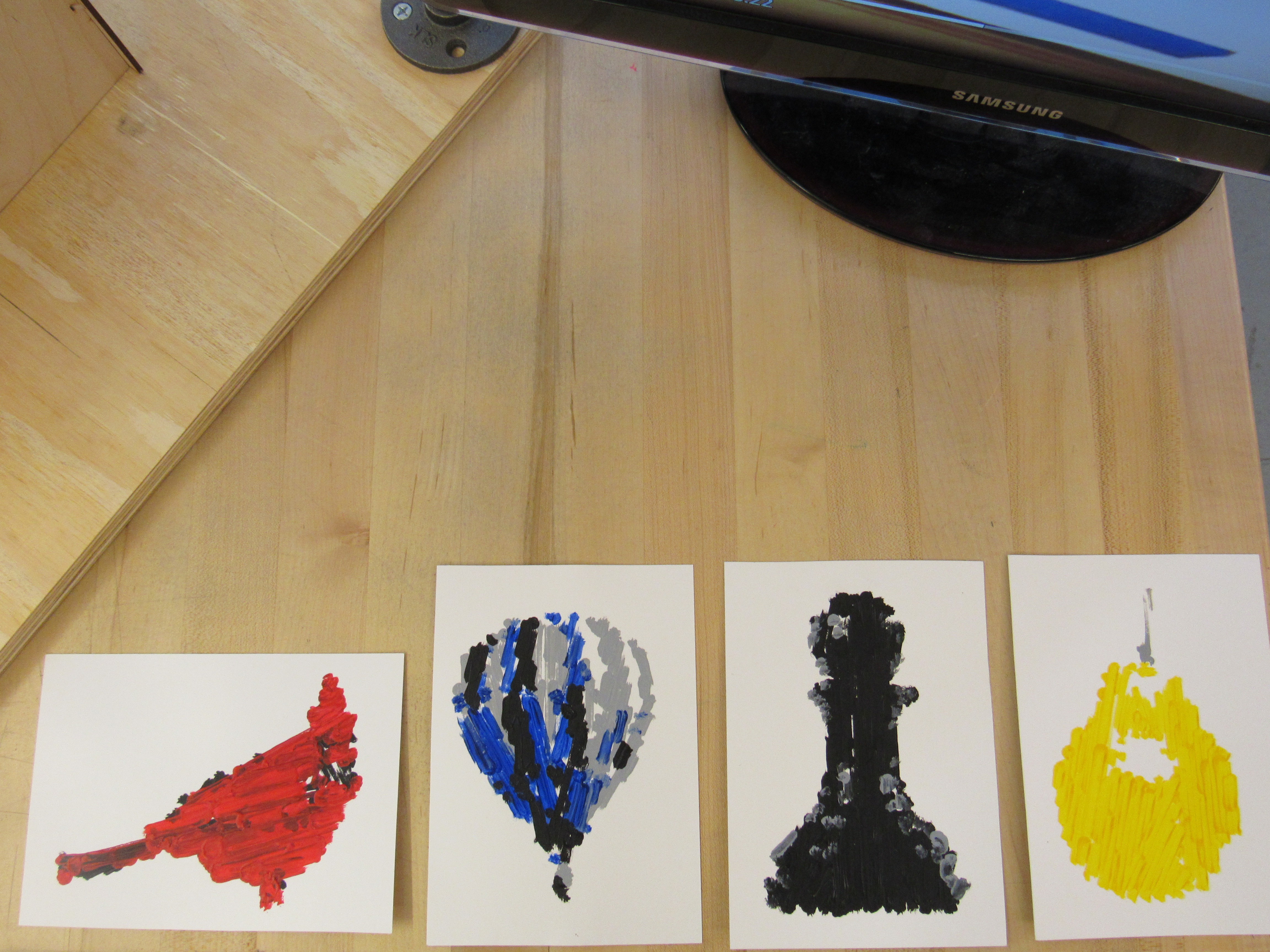
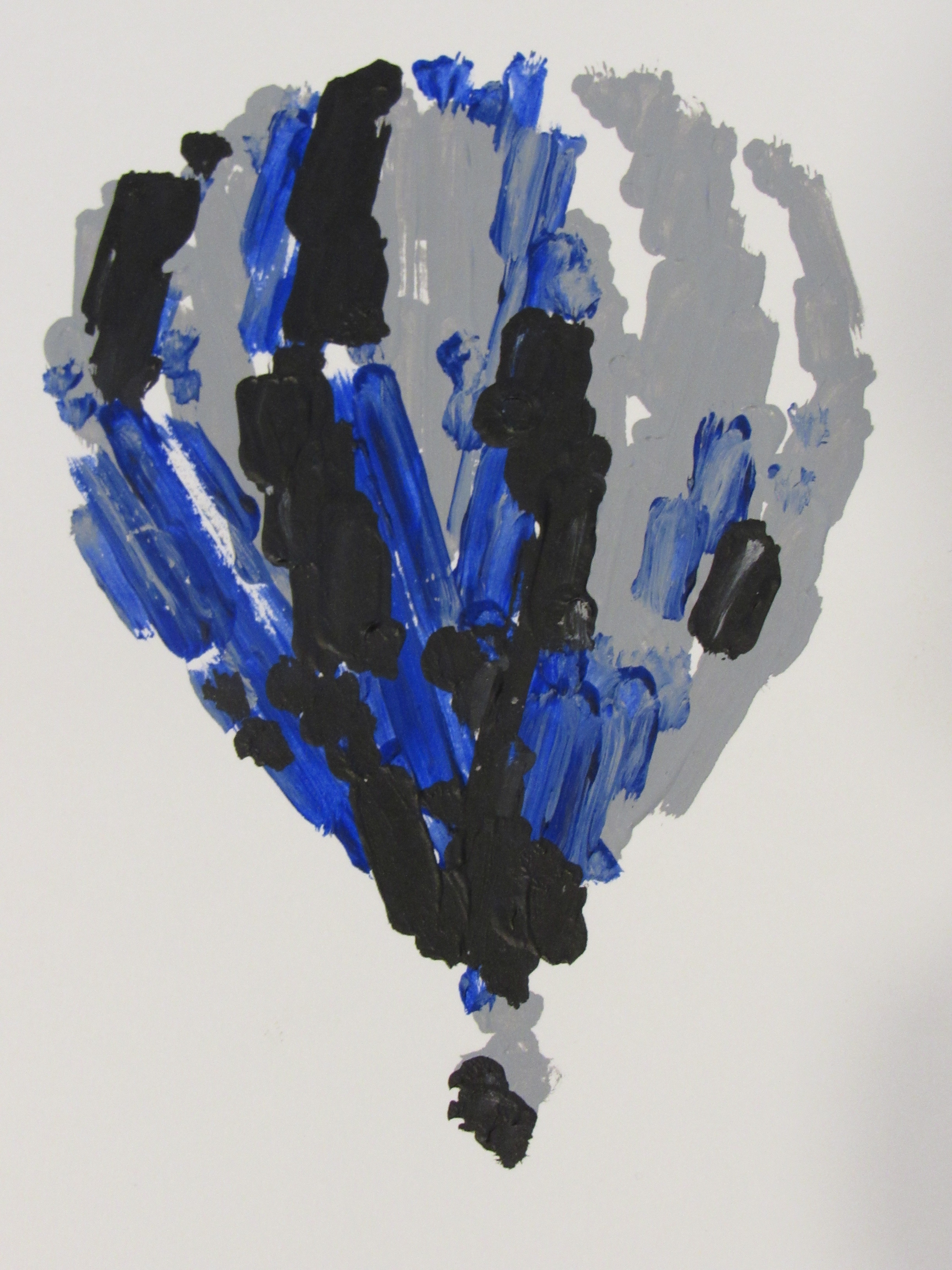
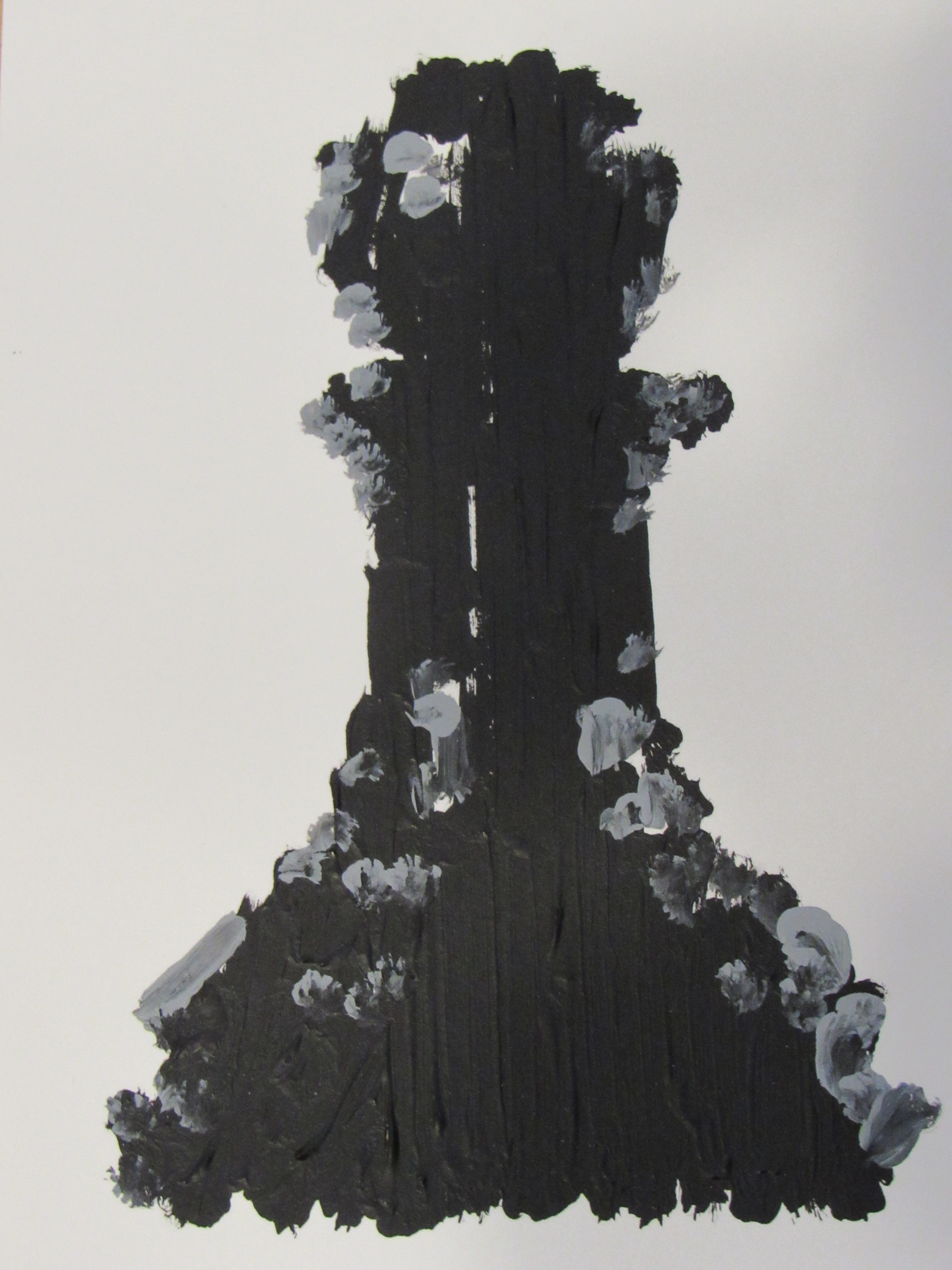
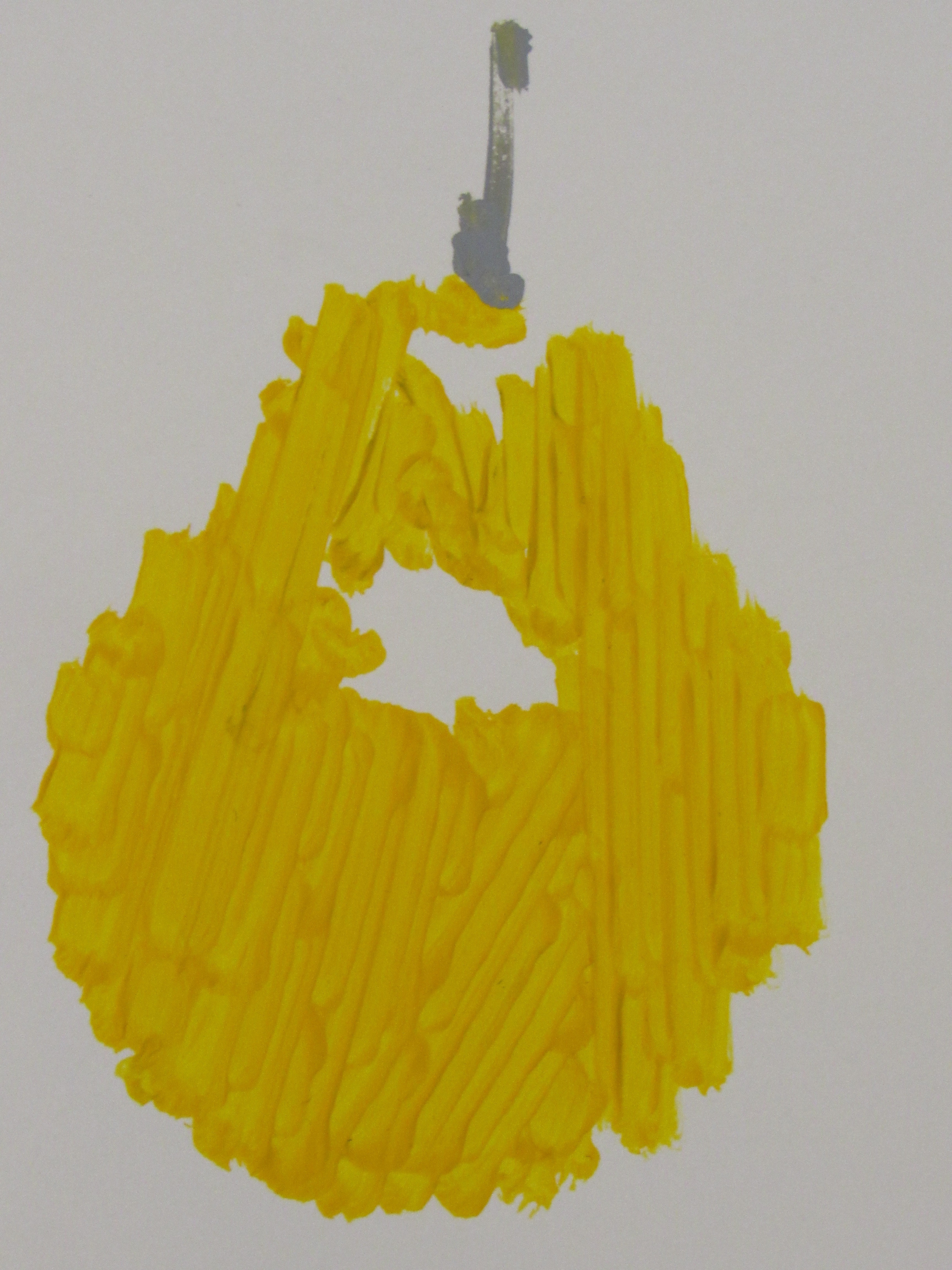
Once I had figured out painting settings that worked reasonably well, I painting several more. The hot air balloon was my first attempt at a three color painting. The chess pawn exposed a flaw in my algorithm that I was able to fix. The pear was a great example of paint stroke placement with the longest line algorithm. Overall, I was pleased with the paintings and became more excited with the project after finally putting paint to canvas.
![]()
![]()
![]()
These first paintings also solidified my decision to start working towards a fully automated cnc painting system. I wanted a system that performed brush changes, cleaned the brushes, and dispensed paints without my help.
-
generate paint strokes from a bitmap image
07/16/2019 at 03:30 • 0 commentsAfter completing the six axis cnc mechanical design, I switched gear and focused on developing an algorithm that would generate paint strokes from any bitmap image. This log will describe the details of the algorithm and how I arrived at it.
At the start of development, I committed to the following requirements:
- Must work on any bitmap image. This includes high detail images, low detail images, images with thousands of colors, images with only two colors, rectangular images, images of irregular shapes, etc.
- Accommodate all brush profiles. This includes all brush types (filbert, round, flat, angle, etc.) and brush sizes. Also, allow any number of brush profiles to be used for the painting or even a single color of the painting.
- Find the brush strokes that a human painter might choose. This is an attempt to find paint strokes along the "natural" contours of the image. I generalized this as the "window frame" problem. See details below.
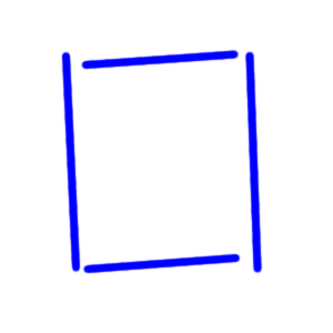
The purpose of the window frame problem is to define "human" painting style in a mathematical context. The window frame problem goes like this: Suppose you are asked to paint a rectangular window frame (like the one shown below) on canvas. Which brush size and paint strokes do you use?
![]()
Regardless of which brush size you use, I propose that 99% of the time, you (and other humans) choose brush strokes that run parallel to the perimeter of the frame. The other 1% of the time you choose brush strokes that run at other angles relative to the perimeter of the frame and would most likely be doing so for artistic effect. The window frame problem is how do you develop an algorithm that will choose brush strokes that run parallel to the perimeter of the frame?
Before I evaluate my brush stroke algorithm against the window frame problem let me explain at a high level how the algorithm works:
- Scan across an image (at an angle relative to the horizontal) using a pixel evaluation size that matches the selected brush profile. Brush profile being the area that a brush covers when it contacts the canvas.
- If a specified percentage of the pixels in evaluation of the scan (typically 90% or greater) match the current color being painted, mark those as valid areas.
- If several valid areas are adjacent to each other along the angle that the image was scanned, connect these valid points to form a brush stroke line.
- Repeat steps 1-3 for multiple scan angles between 0 and 180 degrees from the horizontal.
- Combine all possible brush stroke lines into a single list (call it brush_strokes_all and order in decreasing length.
- Take the first brush stroke line of brush_strokes_all list (i.e. the longest stroke line found during all scans) and put it in another list. Lets call the other list brush_strokes_final.
- Take the next brush stroke line of the list and determine if it overlaps any brush stroke lines currently in the brush_strokes_final list. If it doesn't overlap, add the brush stroke line to the brush_strokes_final list. If it does overlap, do nothing and move onto the next brush stroke line in brush_stroke_all.
- Repeat step 7 until all brush stroke lines of the brush_stroke_all have been evaluated. The brush_strokes_final is now a list of all the longest possible brush stroke lines that do not overlap.
- Void all areas of the image covered by the brush stroke lines in the brush_stroke_final list.
- A few pixel areas the size of the brush profile may still be available at this point due to the no overlap rule. Rerun steps 1-9 until no new brush stroke lines can be created from the image. At this point that algorithm has captured all brush stroke lines needed to cover one color of the image.
- Repeat steps 1-10 for all paint colors.
Step 7 is currently my best attempt at solving the window frame problem. It is still an approximate solution because the image would have to be scanned at 0 and 90 degrees from horizontal to capture strokes that are parallel to the perimeter of the frame. Additionally, if the brush profile is significantly smaller than the frame width of the window frame and the image is scanned at angles close to 0 and 90 degrees from horizontal, the algorithm will find the longest brush stroke lines along the diagonal of each side of the frame (as opposed to the longest lines parallel to the perimeter; see blue strokes of example below). The resulting brush stroke lines from the algorithm sometimes look like a wood grain pattern. I certainly was not expecting to discover something organic looking when trying to paint a rectangular square window frame.
![]()
Progressing from low detail to high detail is a feature that I have not yet explored with this algorithm. It should be possible to start with larger brushes for each color and gradually move to smaller brushes for finer detail. My first thought to make a complete solution for this is to modify step 9 of the algorithm. Instead of voiding all area covered by the brush stroke lines, only void the pixels in the area covered by the brush stroke lines that match the paint color. By not voiding the 10% or fewer pixels that don't match in color, the algorithm will be able to define paint strokes at those locations when a smaller brush is used.
There is so much more to develop and refine with this algorithm and other methods for generating paint strokes from bitmap images. I will post the algorithm code to this project after I have cleaned it up and added comments.
Recommended reading on stroke-based painterly rendering algorithms:
- A Survey of Stroke-Based Rendering by Aaron Hertzmann: http://www.dgp.toronto.edu/~hertzman/sbr02/hertzmann-cga03.pdf
- Artistic Composition For Painterly Rendering by T. Lindemeier, M. Spicker, and O. Deussen (Univeristy of Konstanz, Germany)
- Feedback-guided Stroke Placement for a Painting Machine by O. Deussen, T. Lindemeier, S. Pirk, M. Tautzenberger (University of Konstanz, Germany)
- Image Stylization with a Painting Machine Using Semantic Hints by T. Lindemeir, S. Pirk, O. Deussen (University of Konstanz, Germany)
- Artist Agent: A Reinforcement Learning Approach to Automatic Stroke Generation in Oriental Ink Painting by Ning Xie, Hirotaka Hachiya, and Masashi Sugiyama (Tokyo Institute of Technology, Japan)
- Creativity Is Probably Just a Complex Mix of Generative Art Algorithms by Pindar Van Arman: https://medium.com/datadriveninvestor/creativity-is-probably-just-a-complex-mix-of-generative-art-algorithms-6d37a0087e86
-
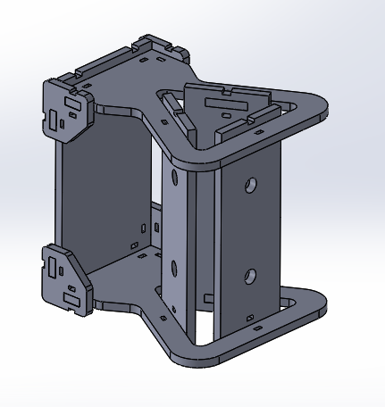
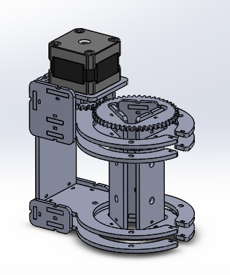
six degrees of freedom brush position control
07/13/2019 at 22:14 • 0 comments![]()
![]()
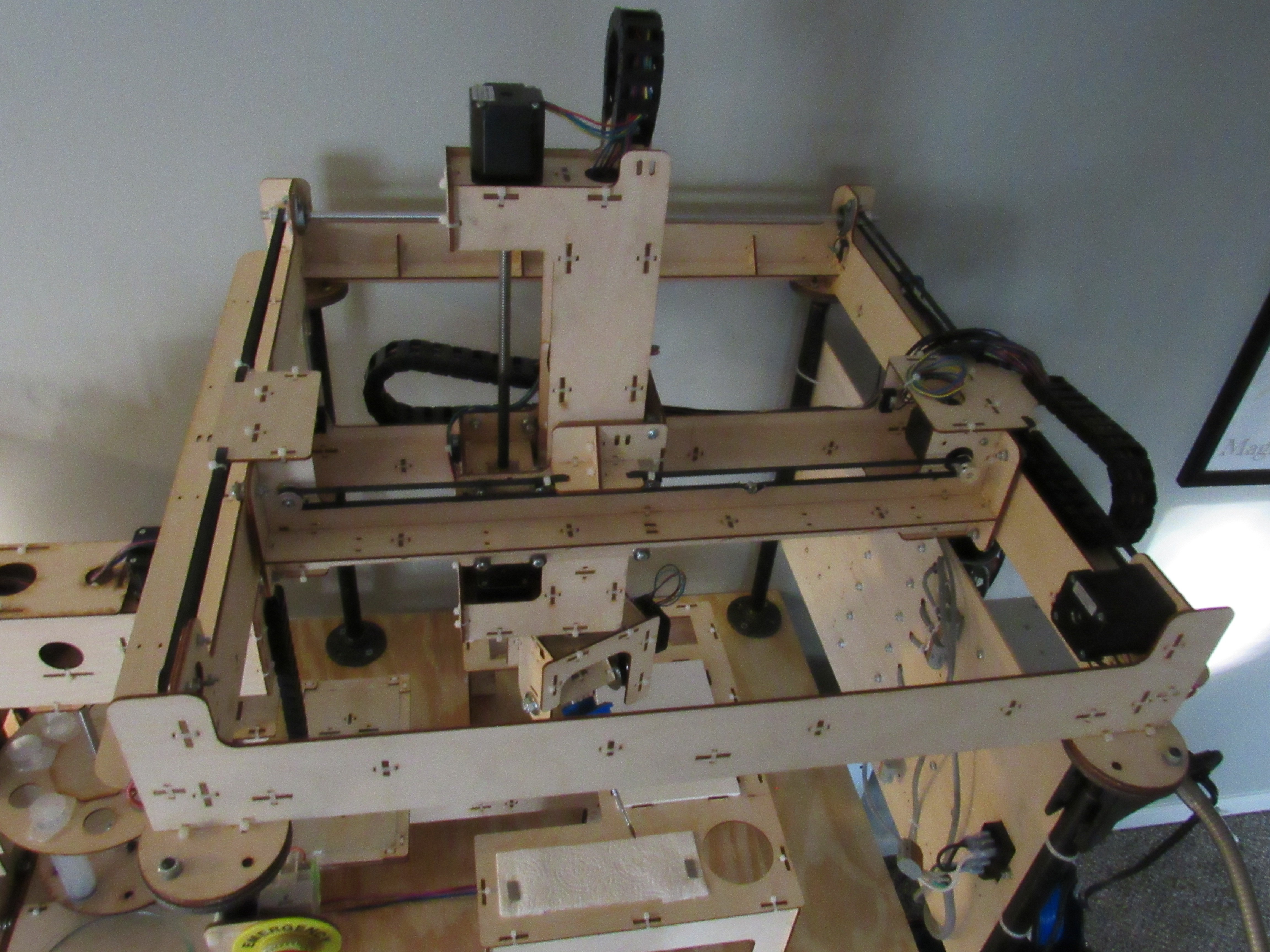
The first major challenge of this project was to develop a cnc machine that can orient a brush in any position relative to a horizontal canvas. There are two parts to this challenge -> 1) develop a cnc machine design capable of achieving six degrees of freedom, 2) identify a microcontroller and a gcode interpreter that can be used to operate the machine.
At the start of the six axis cnc machine design effort, I committed to the following mechanical design constraints:
- Laser cut fabrication of 1/8in Baltic birch plywood for all structural components. 1/8in Baltic birch plywood is readily available through specialty lumber suppliers in Kansas City. It is a common material for laser cutting because of its relatively low price and high stiffness to thickness ratio. 1/8in Baltic birch seemed to be stiff enough based on my previous wall plotter project.
- A maximum laser cutter bed size of 300x600mm (12x24in). At the time, 300x600mm was the maximum bed size of the laser cutter at the Johnson County Central Resource Library in Overland Park, Kansas. Laser cutting is free at the library. Yes, I did all the laser cutting for this project at a library and it didn't cost me anything but taxes and time (guessing 10+ hours total).
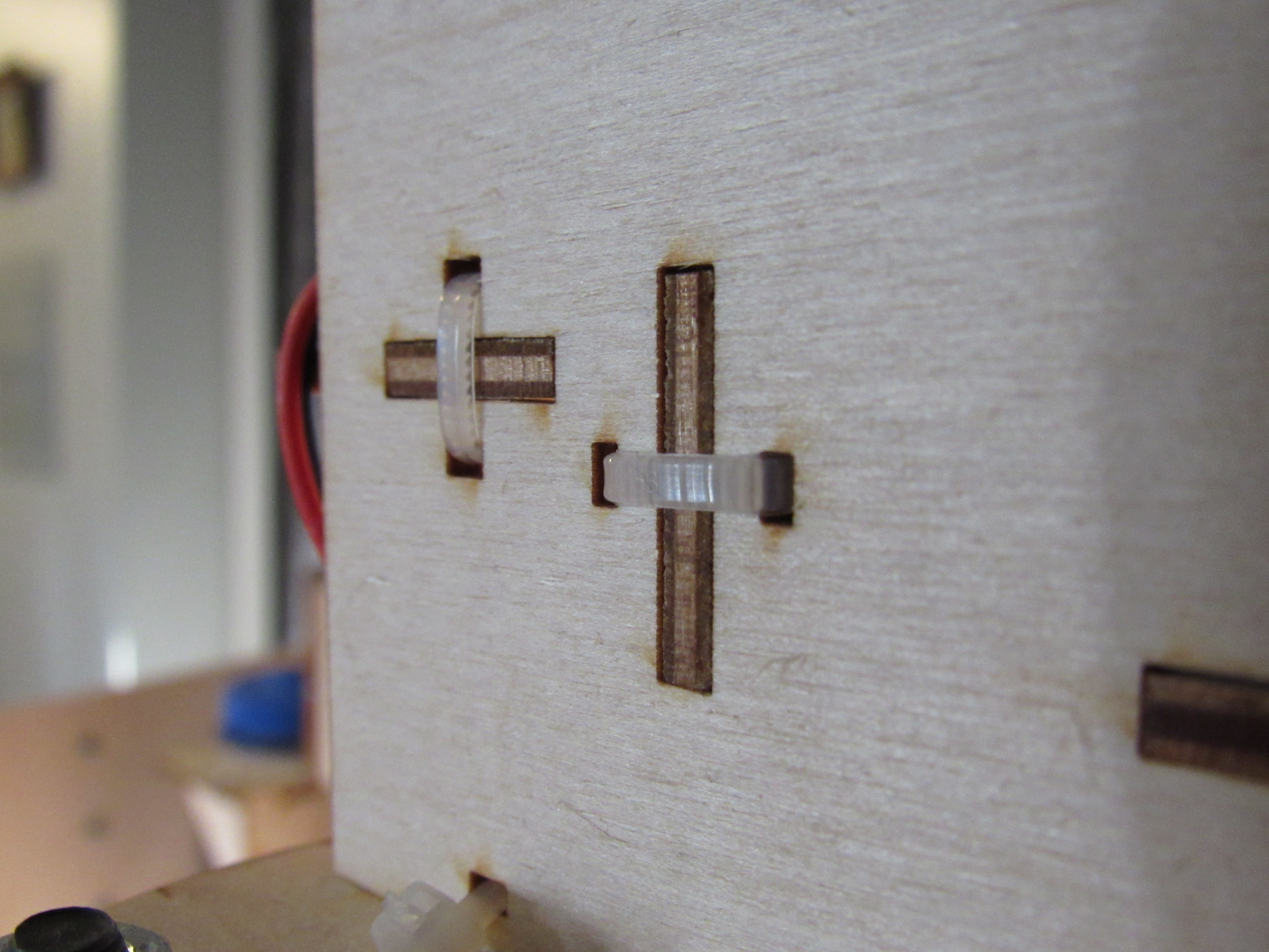
- Tongue and groove with a 100mm zip tie method to fasten all structural components together. This fastening method worked really well for my wall plotter project, so I ran with it on this project as well.
![]()
- 4x13x6mm v-bearings for all linear rails. Once again, this was a carry over from the wall plotter project. It is a cheap solution that gets the job done.
![]()
I was able to get away with using a structural material with low stiffness (at least compared to other cnc machines) because the end effector of this application (i.e. a brush) is so light weight. The large electric motor at the end effector typical of cnc mills was not needed. In addition, cnc canvas painting is not a precision machining operation. A little wobble or flex in the machine structure during operation is acceptable. Maybe even desirable if it makes the painting look less robotic.
The development of the mechanical design began at the end effector, progressed to the three axis head, and finished with the three axis gantry. Hundreds of design decisions were made throughout the process. It doesn't seem practical to document all of those details here. In fact, it's probably even quicker if you just take a look at the design and use your best mechanical intuition to make a guess on why something was done one way and not the other. The tip I will give you is that at no point were aesthetics considered in the design. The form of all structural components is purely a result of function. A solid model .step file of the six axis cnc painter is attached to this project.
Additional notes about the mechanical design:
- A wire slip ring is used between the three axis head and three axis gantry to allow infinite rotation of the three axis head.
- Wire management rails are used on the x, y, and z axes.
- Limit switches are placed at both ends of each linear gantry axis for homing and preventing damage to the machine during operation. No limit switches are incorporated into the three axis head rotatory axes. Instead, each rotary axis has a physical method for setting the zero position.
- Outside dimesions of the six axis cnc painting machine are approximately 710x710x915mm (28x28x36in)
- Total workspace area when the brush is in the vertical position is approximately 300x400mm (12x16in)
- Z-axis movement: 205mm
- Three axis gantry accelerations should be adjusted so that the machine does not shake during operation.
Identifying a microcontroller and gcode interpreter were the next part of this challenge. I initially started out using Mach3 and it worked great. But I really wanted a cheap open source option. I ended up making my own branch of grbl-Mega-5X and made modifications to allow six axes control and six limit switch inputs (https://github.com/johnopsahl/grbl-Mega-5X). An Arduino Mega 2650 microcontroller is needed to run grbl. There are still a few issues with the homing routine but otherwise it has worked great so far. I use the cncjs Gcode sender because it is open source and supports up to six axes (https://cnc.js.org/).
It was an exciting moment when all six axes moved using one gcode command.
If ( ) Then {Paint}
a machine to create canvas paintings of your favorite digital images