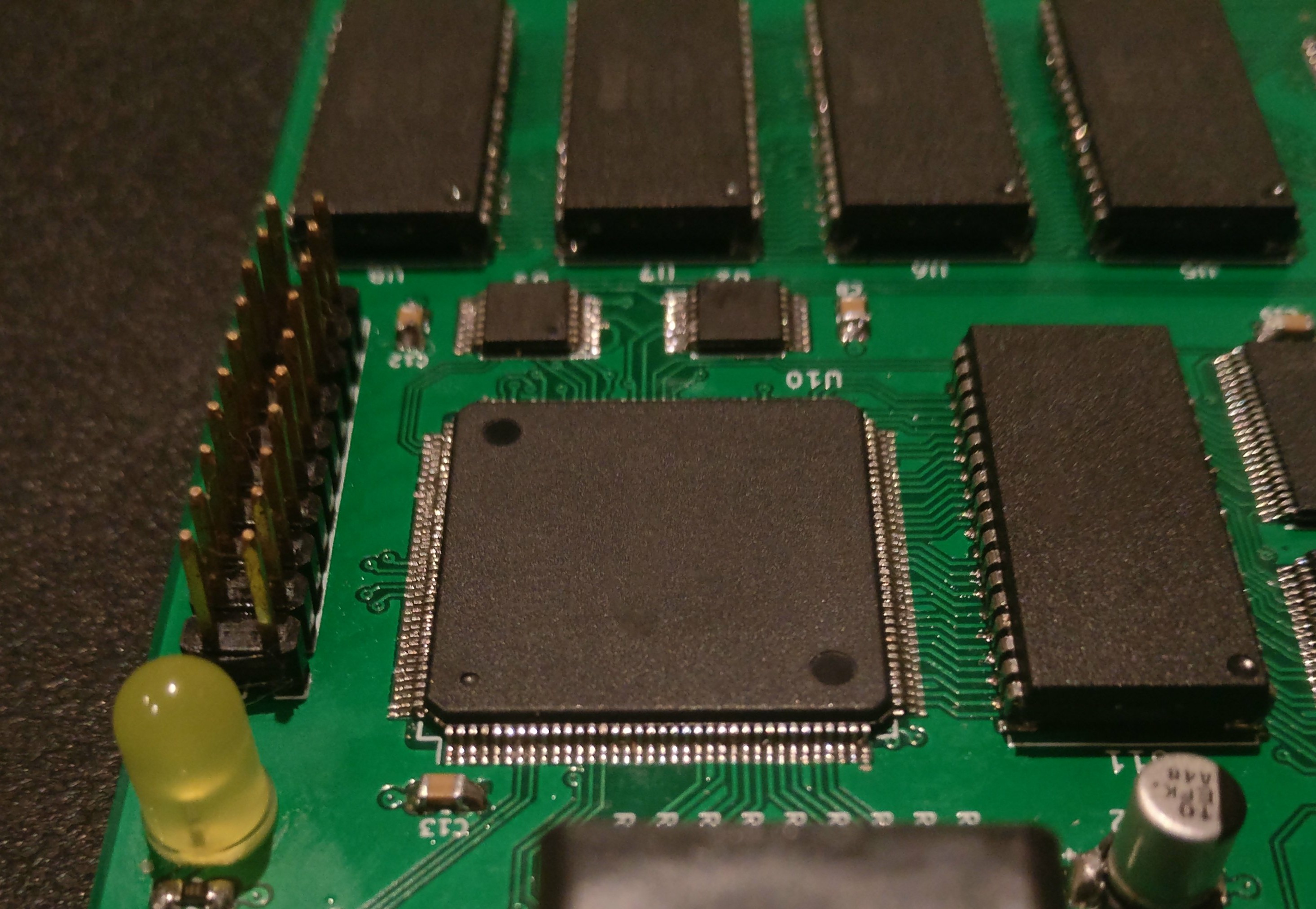
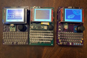
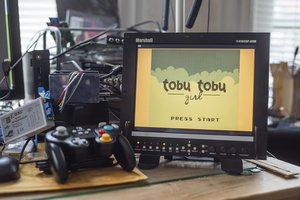
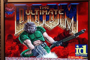
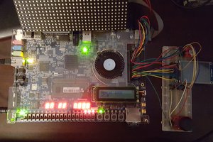
The GitHub repository for the FPGA core itself can be found HERE. The core is what most of this project is focused on, but there will be a lot of hardware testing along with it.
An m68k homebrew with an FPGA acting as a VGA graphics controller
To make the experience fit your profile, pick a username and tell us what interests you.
We found and based on your interests.
The GitHub repository for the FPGA core itself can be found HERE. The core is what most of this project is focused on, but there will be a lot of hardware testing along with it.
Diapason-KiCad.zipThe KiCad project files for Rev.A of DiapasonZip Archive - 264.09 kB - 07/12/2019 at 20:20 |
|
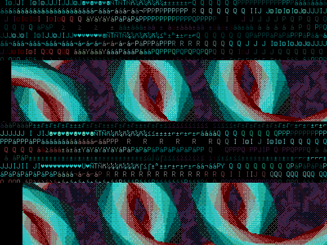
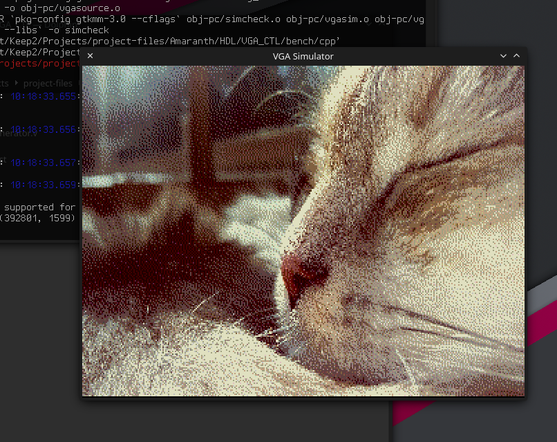
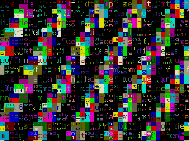
Before the rest, I wanted to mention I made a new test image for the bitmap modes. The new one shows artifacting much better than the old one, and is a little more visually interesting:
This is what I'll be using from now until I decide to change it (never). Above is what it is supposed to look like, so if it doesn't match then you know something is broken.
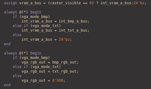
First and most important thing, I fixed the strange bug causing the pixels to change size! The problem was with the way I was multiplexing the internal buses with the external ones. I have no clue how exactly this caused the screen to do what it did, but at least its fixed. The old logic driving it was this:
The new working logic seen here:
However, I noticed another bug playing around: The screen is shifted up by two pixels, even when the scroll register is 0. I don't think this bug was caused by anything recent, because I looked back at the Images on my previous project log and It's there too! It flew right under my radar, probably because it blended in with my desktop theme's black frames. I only noticed this because I accidentally made the background colour off white (again, no idea how), causing those lines to become a blinding beacon to my eyes:
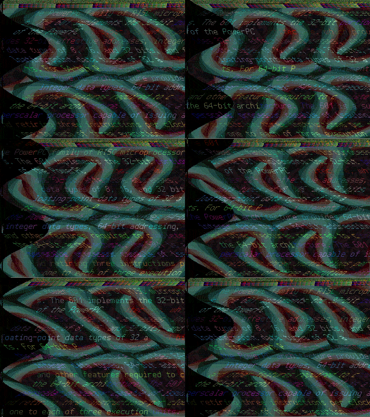
I've tired myself out implementing new things as of late, so I spent some time just playing with it and trying to generate interesting effects. Here's a few of the ones i thought were the most interesting:
I'm pretty pleased with what I was able to get out of Diapason so far, to say the least. This time I'm going to focus solely on bringing the hardware up, any maybe a bugfix.
And here's that list of future feature ideas:
This log is going to focus mainly on the FPGA core, as I am still having some teething issues with the hardware. I'm fairly sure the Altera USB Blaster isn't going to play nicely with it until I put pull-up resistors on a few of the MAX10's configuration pins. I have yet to get around to doing this, but do have some good progress on the FPGA core to show.
Finally, I've implemented a separate bus for the host CPU to communicate to the controller with, as seen in the following verilog code snippet:
The bus is asynchronous, and is updated at the 50MHz core clock. I chose an async interface mainly because a synchronous bus is a huge pain to debug when it inevitably fails to transfer correctly. vga_ack is the transfer acknowledge output, which is set as soon as the controller realizes it's being accessed, and unset after vga_select is unset by the host.
The verilator testbench has received updates to test this functionality as well. It keeps track of what pins to change each cycle by keeping track of the total number of bus cycles, then just doing something different each time. The count number is also abused a bit; it is set arbitrarily a few times to force the next bus cycle to start something entirely different.
Here's the current list of registers accessible through the bus. The function of each register is described either by the blindingly obvious name, or through the comments next to its definition.
The controller can now generate interrupts! They can be enabled by setting one of the enable bits in register 4. Currently, the only implemented interrupt type is the raster interrupt, but I have reserved space for an interrupt generated at the start of the vertical blanking period. The line that triggers the raster interrupt is set using registers 5 & 6; two registers, one as the high byte, and one as the low byte.
The current raster number is checked every cycle, which means it is able to be triggered halfway through a line. I can't imagine any possible way for that to be useful, but it is good to note.
Last project log, I mentioned that I would like to try adding a scroll register; I ended up doing that, both for X and Y. Each register is 8 bits wide, which allows them to move the display data up to 255 pixels in their respective directions. Here's the X scroll reg being set based off the current scanline:
Now, this isn't an entire screens worth of data, as seen above by the sudden resets to 0. If you wanted to scroll any amount past 255 pixels, you would have to manually move the entire brick of VRAM, which can be as large as ≈300KB. If you wanted to do smooth scrolling of the entire screen, that would be pretty abusive to the host device. I'm not 100% sure yet, but I'll probably end up adding an extra register with the 9th bits of each axis so that I can offload as much mindless blitting to the controller as I can.
Yes, and it's only slightly broken! The first thing I tried was using the raster interrupt to change the X scroll register halfway down the screen:
At first look, it seemed to work wonderfully (aside from the very-on-purpose tear in the middle)! It also exposed the first issue: the very obvious error with the first column of pixels. Upon closer inspection, the first column is actually being displayed 1 line early:
After the raster split, the first column also becomes some data I honestly cannot find the source of in the bitmap. Even though this didn't appear previously, I'm not convinced it's entirely new behavior, since the issue goes away if I just set it to bitmap mode and leave it. Even more confusing is that the data actually displayed changes based on the current scroll register value! After an hour or two, I really have no clue where this anomaly is produced. The video mode modules themselves are certainly suspect,...
Read more »As far as hardware goes, assembly is pretty much complete! All that is left is actually getting the FPGA core onto the thing, which has proven to be a little more difficult than I had intended. I have tried a few methods of programming the FPGA through JTAG, which didn't work, but I think i can get this one to function. There are a few pages online that discuss using a Bus Pirate as an XSVF player; I tried using it for plain SVF playback with openOCD, but that didn't seem to do anything. It looks like the Bus Pirate is only capable of playing back XSVF files, probably because of its limited onboard memory. Regardless, that's the method I'll try next time I work on the board.
On a more positive note, openOCD did correctly recognize and identify my FPGA over JTAG. So at the very least, the design is sane enough to not blow up its components.
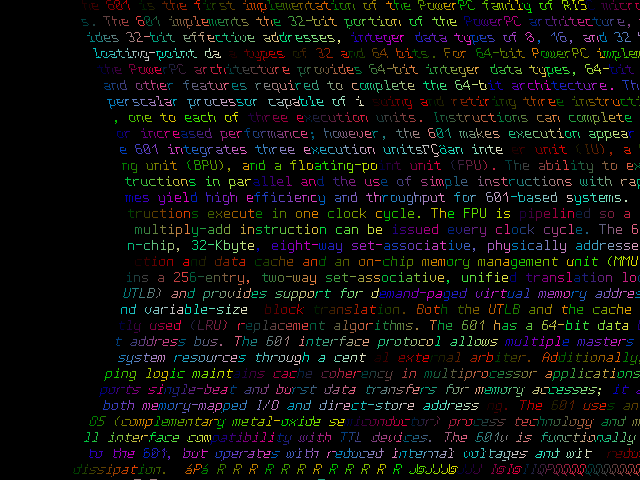
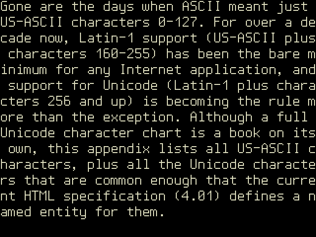
Despite the hardware not really existing in a functional state, the FPGA core is actually pretty far along in development. I have been using Verilator to compile the core and simulate it locally. I have a verilator test-bench using a VGA monitor simulator that i found somewhere online that i have modified to interface with my verilog sources. If the simulator is to be believed, my core's VGA signal generation is at least functional:
And maybe a bit more than functional, as well. So far i have 2 distinct graphics modes implemented:
The verilator test bench also simulates the VRAM that the core grabs the graphics data from, and can pre-load data into the VRAM on startup.
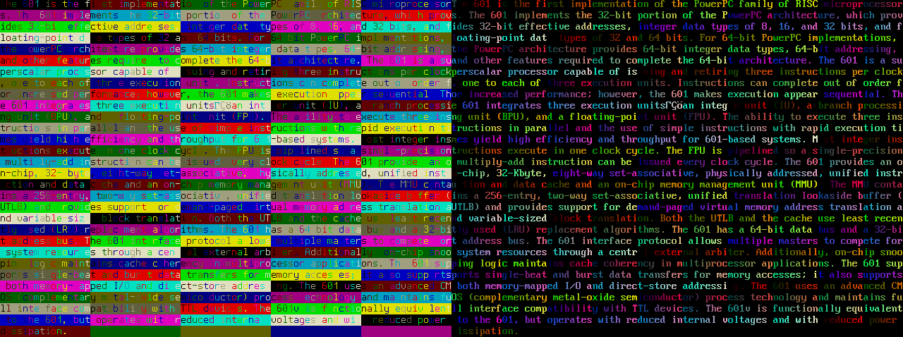
The text mode has a few configuration bits that it uses to alter aspects of the display. So far it can either do 256-color text mode, or VGA compatible 16-color foreground+background text mode:
More config bits include the ability to double the height of a character and double the width of a character:
Of course, you can twiddle any of these bits in any combination you like:
Here, you can see a vertical line at the start of a lot of the color cells; As far as i can tell, this isn't an issue with my VGA timings, Its just an artifact of how I'm generating these register values. I'm feeding the X and Y registers back into the config register, which creates a double registered input, thus the 1 cycle delay. (In theory, anyways)
This happens to show how I'm actually fetching things from memory. In the text mode, I'm fetching the attribute byte in the first cycle on the X axis, and the character value in the second, and all that gets repeated nonstop. This leaves 0 cycles left for anyone else to access the framebuffer and is something that's going to need to be optimized. I'm thinking about fetching the character value and attribute byte once per cell on the first scanline of each character, and saving them in a buffer. That way i can leave 98% of the cycles open for the CPU to fiddle with the framebuffer (or even more more if the X any Y are expanded!).
Another part that needs work is the bus that the host CPU uses to write and read to the FPGA's internal registers; It needs work because it doesn't exist. Currently, to select between text and graphics modes, I'm just flipping two bits on a multiplexer. So the framework is there, i just need to move a bunch of things into registers, and then implement that CPU bus.
lots of stuff still left to do, on both fronts. Cant stop thinking of all my favorite video chips and the special tweaks i want to implement here. Maybe I'll add a scroll register next?
Create an account to leave a comment. Already have an account? Log In.
Great project! I was always interested in implementation of video controllers, lots to learn from here! Does is support all standard VGA modes (classic IBM PS/2 I believe was the first one to have VGA?). I am also very interested to learn about the CPU / VGA memory sharing - is it same or separate memory space, and if same does CPU only have access during H and V sync/blank or something more elaborate?
Become a member to follow this project and never miss any updates
Hmm, I'd love the schematics in an editable form (KiCad, EagleCad) for not only this project but your other 68k project with the 68030. Looking to base myself on both these designs and work from there on my own custom DIY approach. Can you drop a link?