 Andrey Ovcharov
Earlier this year the new standard of secure passwordless authentication was submitted to W3C. Major browser are already in the process of implementing this standard so we can expect that this kind of authentication will be available to the end users very soon. Meanwhile I was playing with the ESP32 development board which features Bluetooth Low Energy connectivity. I think it will be extremely interesting to build personal authenticator device.
0%
0%
URU Key
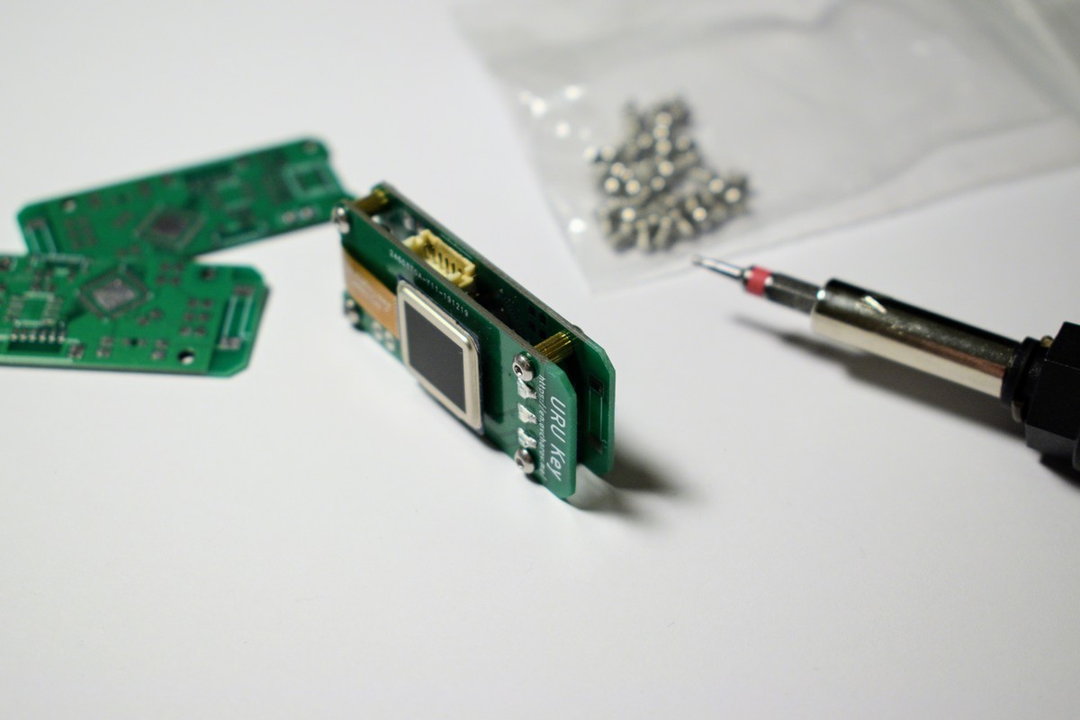
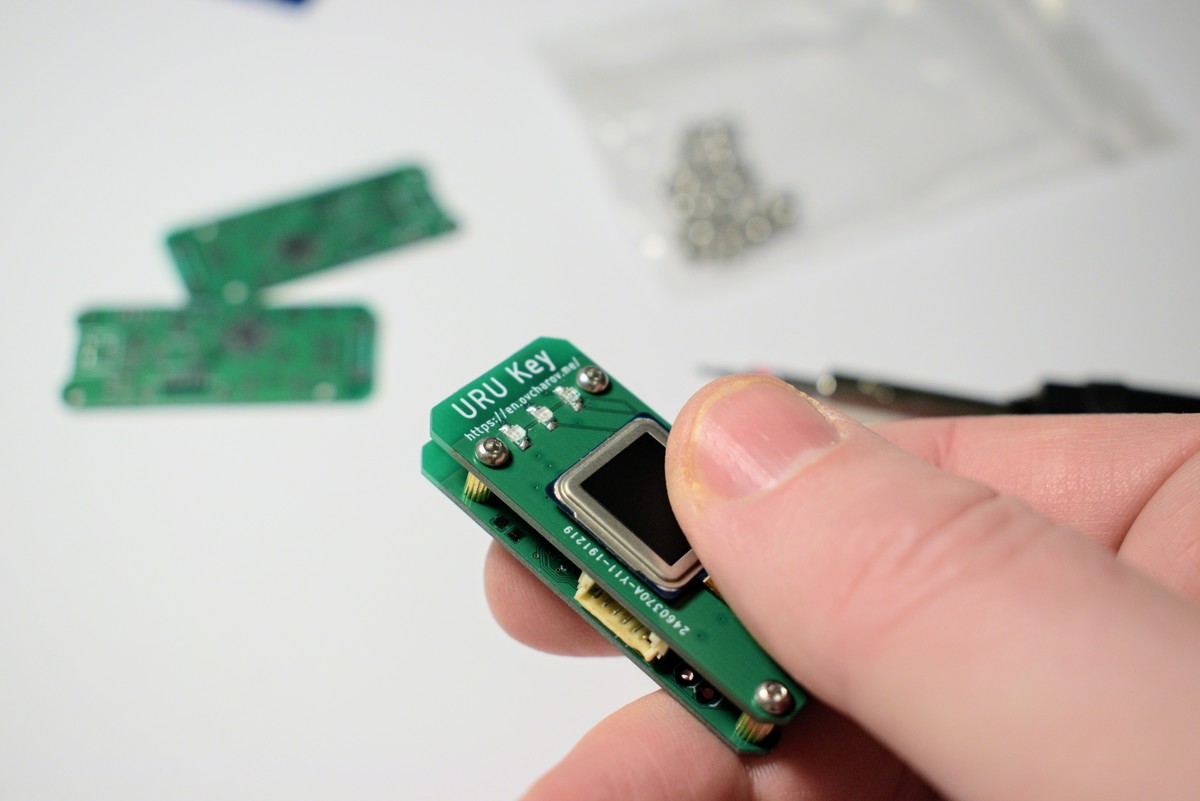
URU Key - a biometric FIDO2 Authenticator
built with ESP32 / ATECC508A / FPC1020
Become a Hackaday.io member
Already have an account? Log in.
Just one more thing
To make the experience fit your profile, pick a username and tell us what interests you.
Pick an awesome username
hackaday.io/
Your profile's URL: hackaday.io/username. Max 25 alphanumeric characters.
Pick a few interests
Projects that share your interests
People that share your interests


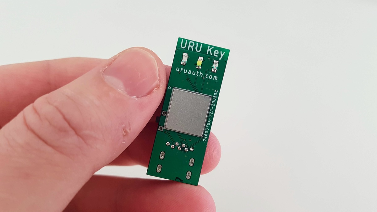


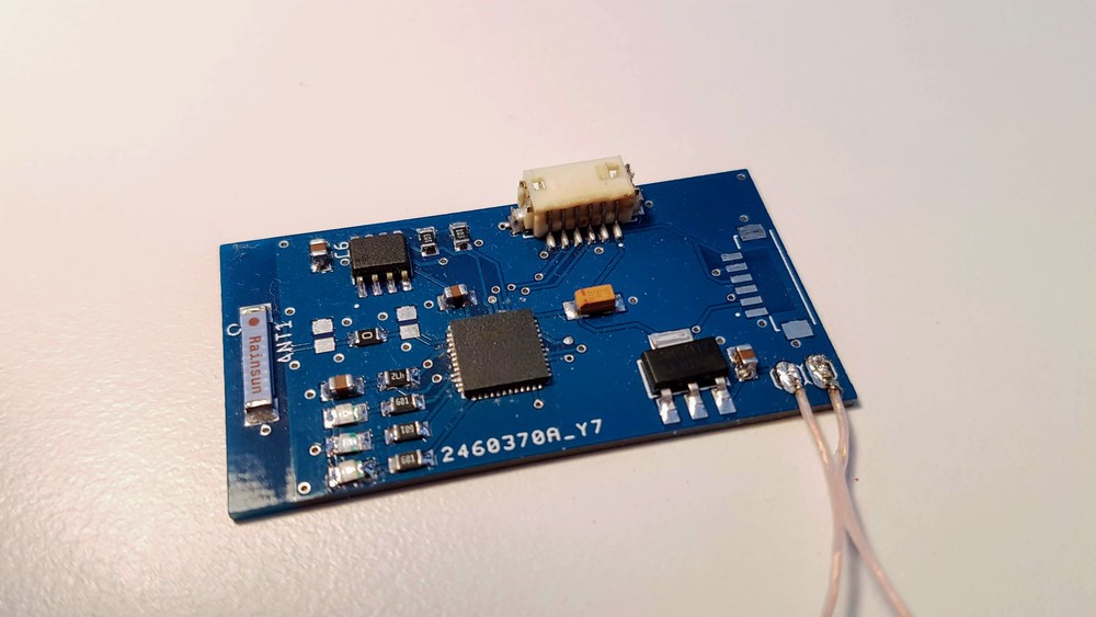
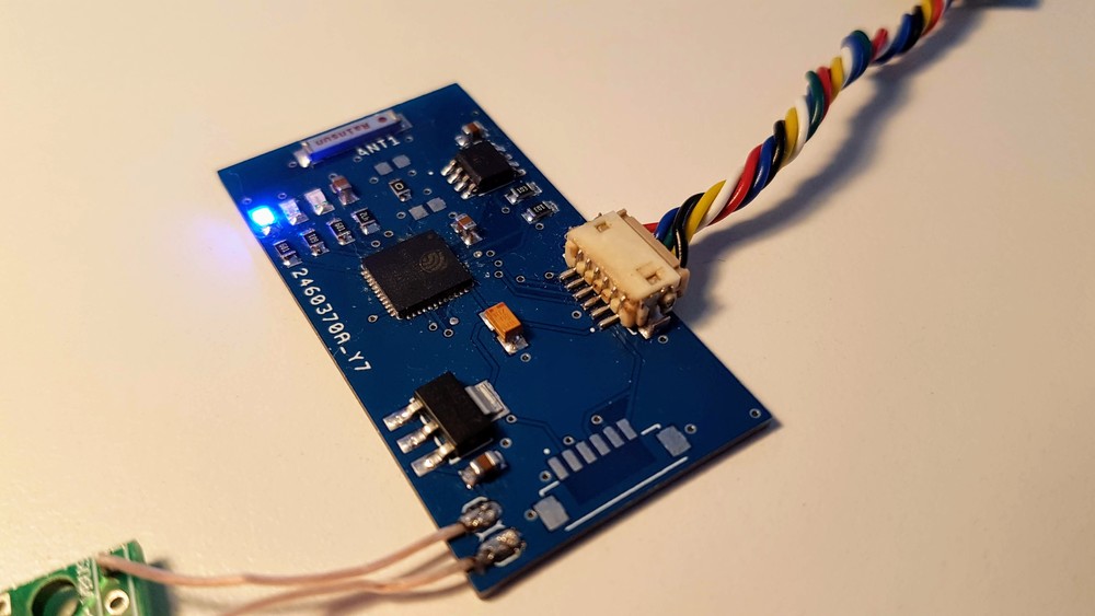
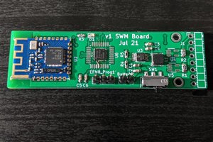
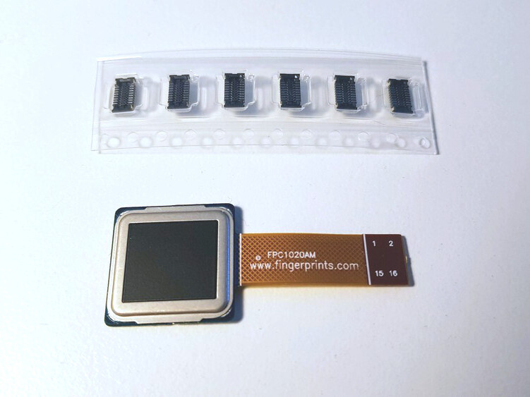 FPC1020AP is the same scanner in LGA package and I’ve spent some time figuring out how to properly connect it.
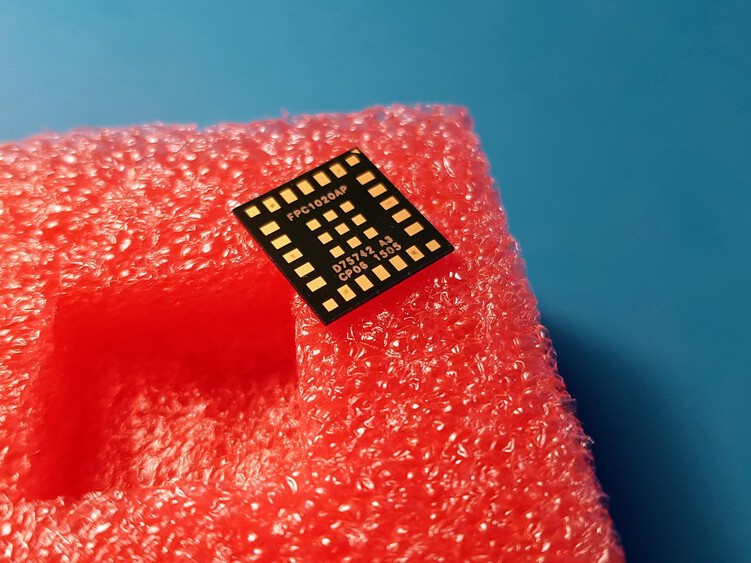
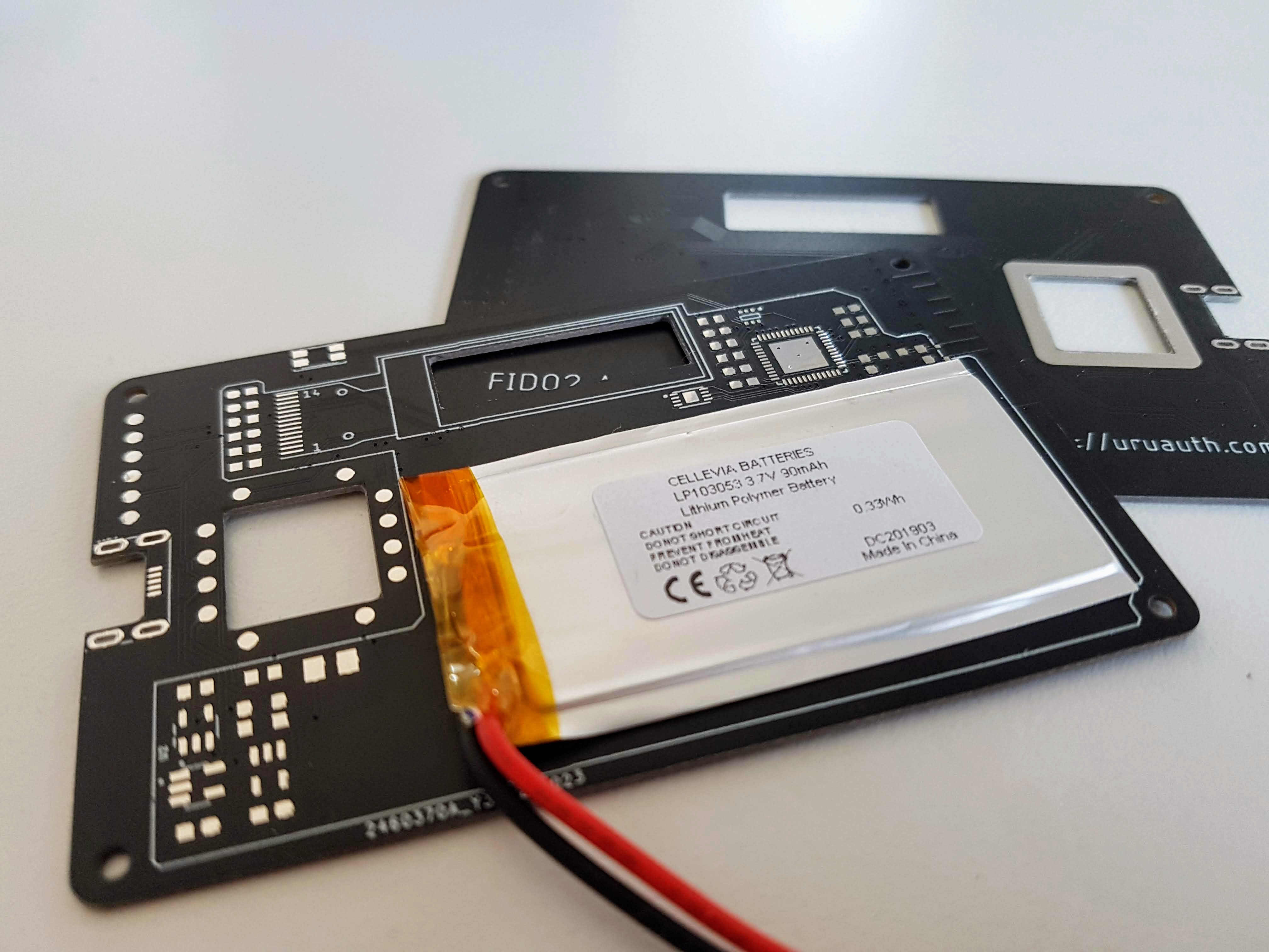
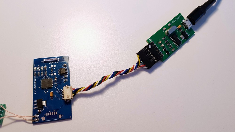
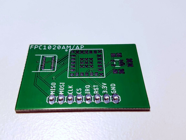 The board is connected to the ESP32 development board with four wire SPI interface.
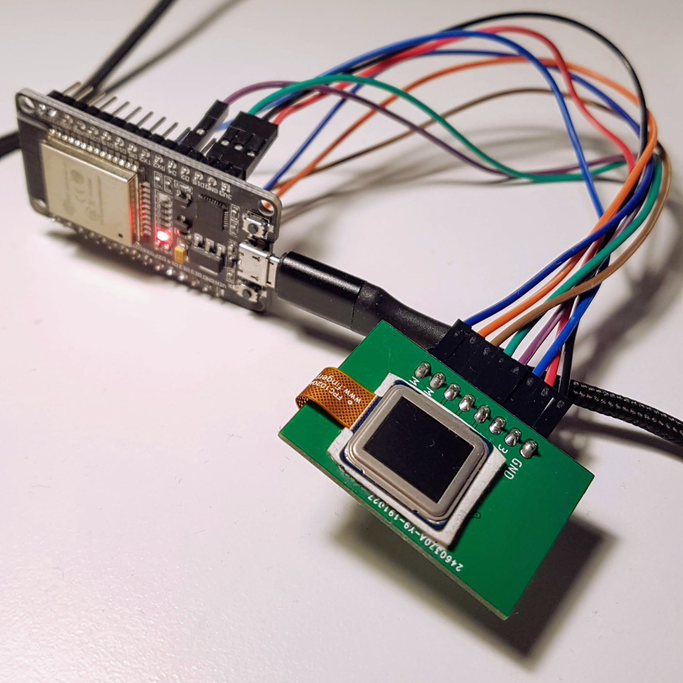


 mulcmu
 Matias N.
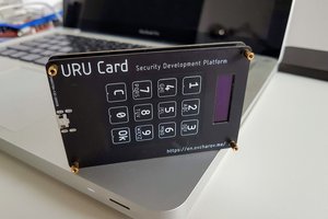
 Ben Lim
You said you won't opensource it due to biometrics.
But perhaps you can make a "URU Key Lite" without fingerprinting, but with a simple click-button (and maybe tiny screen in the freed from fingerprinting space), and perhaps a pair of USB + USB-C connectors for desktop uses ?