 Bin Sun
-
1Parts and Schematics
All the parts are available from Amazon.com and the BOM are provided above.
Additionally, the sensor body and the case which consists of device box and back panel need to be 3D printed using the STL files below. The sensor body should be printed in vertical position with support to for best results.
-
2Build and Initial Testing
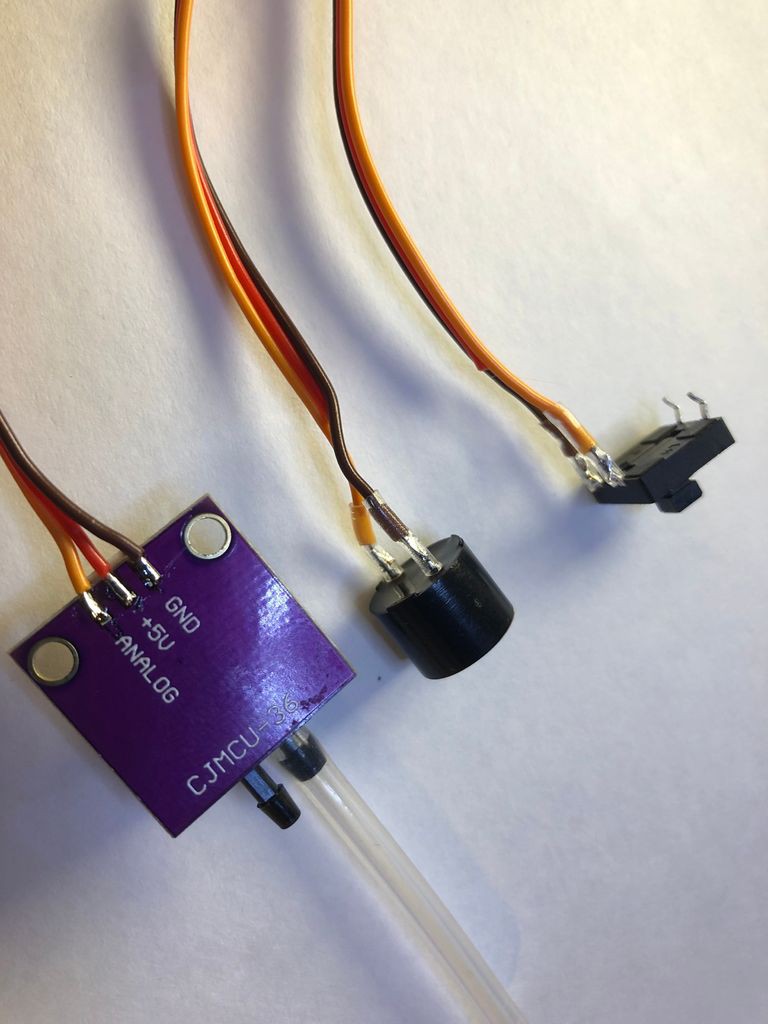
First prepare all the parts for final assembly. Solder the pins to the Nano board if needed then install the Nano board to the I/O expansion board. Then, attach or solder the jumper wires to the button switch and the buzzer. I used some leftover servo connectors instead of jumper wires. For MPXV7002DP, you can either use the wire that comes with the breakout board without soldering or solder the wire to the breakout board as shown in the picture. Also, cut about 30 mm silicon rubber tubing and attach it to the topside port (P1) on the MPXV7002DP.
![]()
![]()
Once the parts are prepared, the final assembly is very simple due to the use of the I/O expansion board and the serial I2C LCD.
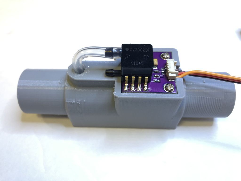
Step 1: Install the MPXV7002DP breakout board to the 3D printed sensor body. Inert the open end of the silicon tubing to the measurement hole then secure the board with 2 small screws. Connect the sensor to the S pin at port A0 on the expansion board.
- Analog --> A0
- VCC --> V
- GND -- > G
Step 2: Connect the LCD to the Nano expansion board S pins at port A4 and A5
- SDL -->A4
- SCA -->A5
- VCC --> V
- GND --> G
Step 3: Connect the Buzzer and Switch to the expansion board port D5 and D6
- Switch: to port 5 between S and G
- Buzzer: to port 6, the positive to S and the ground to G
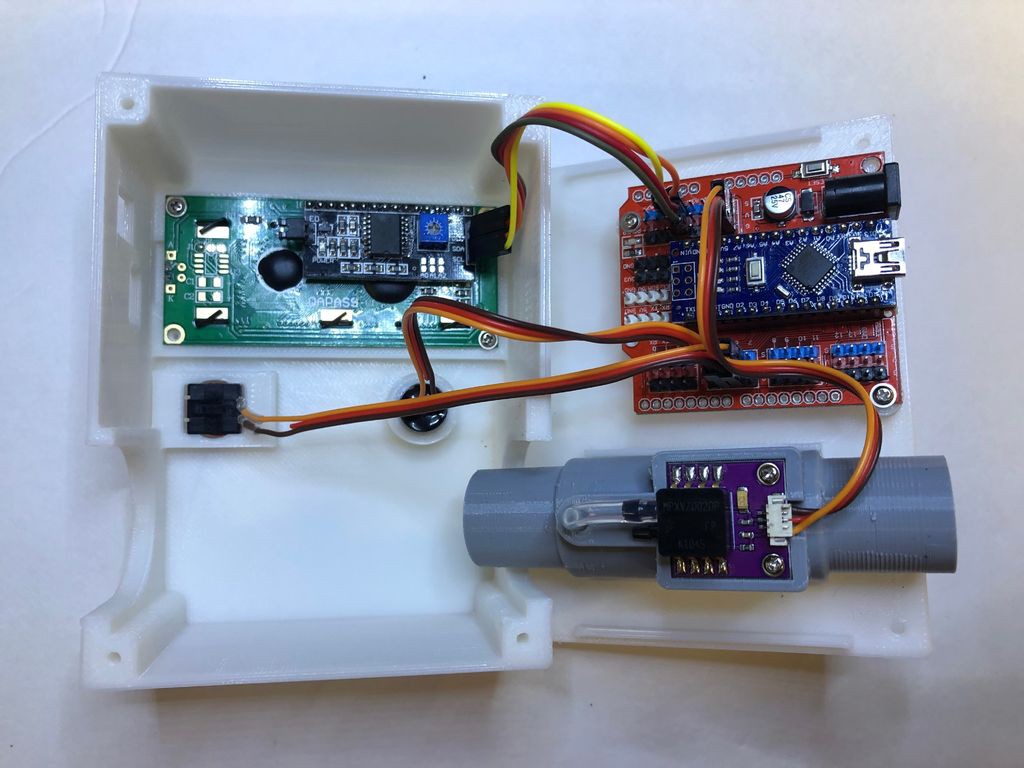
Step 4: Final assembly
Secure the sensor body to the back plate with 4 M3 screws, then install the LCD screen and the Nano expansion board and secure them with small screws. Push the button switch and the buzzer into the case and secure them with hot glue.
![]()
Step 5: Programming
- Add the libraries to your Arduino IDE. The libraries can be found at: LiquidCrystal-I2Cand RunningAverage.
- Connect your Arduino to the computer and install the Arduino sketch.
That's it. Now power the unit up with either USB or apply 9-12V power to the DC port on the expansion board (recommended). If the LCD display back-light is on but the scree is blank or the letters are hard to read, adjust the screen contrast by turning the blue potentiometer on the back of the LCD I2C module.
Finally attach the the back plate to the front case with 4 M3 screws.
-
3Simple Manometer Test Set Up
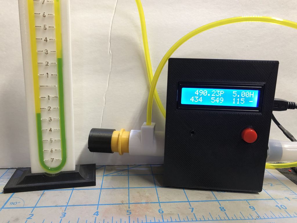
I was curious about the accuracy of this digital manometer and built a simple test stand to compare the meter readout to a classic water manometer. With an electric air pump controlled by a motor speed controller, I was able to generate variable air pressure and took the measurements simultaneously by both digital and water manometers connected in series. The pressure measurements are pretty close at various.air pressure levels.
![]()
-
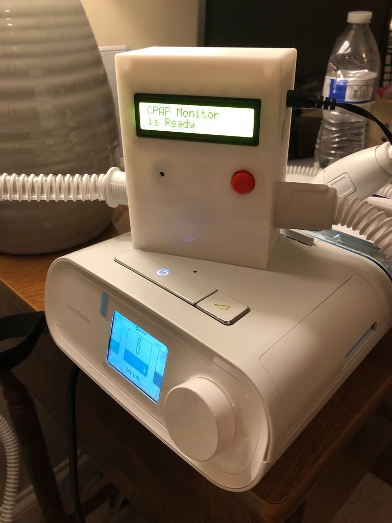
4Put It Into Action
The use of this device is pretty simple. First connect the device inline between the CPAP machine and the mask use standard 15mm CPAP pipe. Connect one side of the monitor to the CPAP machine then the other side of the monitor to the mask so the air can pass through.
![]()
Power-on calibration
The MPXV7002DP sensor needs to be calibrated to zero pressure against ambient atmospheric pressure every time when power-on to ensure its accuracy. Make sure the CPAP machine is turned off and there is no additional air pressure inside the tubing when powering up. Once the calibration is finished, the meter will display the offset value and a device ready message.
The meter operates in either Manometer mode or CPAP Alarm mode by the push of button. It is worth noting that the LCD back light is managed according to the operation mode and sensor value to make the meter less distracting during sleep.
Manometer Mode
This is the standby mode and a "-" sign will be displayed at the right bottom corner of the screen. The alarm function is disabled in this mode. The screen will show the real-time air pressure in both Pascal (P) and the cmH20 (H) at the first row, and the Minimum and Maximum pressure as well as the Difference between Min. and Max. observed in the past 3 seconds at the second row. In this mode the LCD back light will be constantly on but will time-out if zero relative air pressure has been measured continuously for over 10 seconds.
CPAP Alarm Mode
This is the alarm mode and a "*" sign will be displayed at the right bottom corner of the screen. In this mode the meter will be checking the differences between the peak and trough levels of air pressure. The LCD back light will time out in 10 seconds and remains off as long as there's no low pressure difference has been detected. The back light will turn back on again if a difference of less than 100 Pascal has been detected. And the buzzer will sound an audible alarm with a "Check Mask" message being displayed on screen if the difference in measured air pressured levels has been persistently low for more than 10 seconds. Once the patient re-adjust the mask and the pressure difference returns above 100 Pascal then both alarm and the back light will be turned off again.
Digital Manometer/CPAP Machine Monitor
Ever wake up in the morning found your CPAP mask is off? This device will alarm you if you have unintentionally removed mask during sleep.
Discussions
Become a Hackaday.io Member
Create an account to leave a comment. Already have an account? Log In.