 Andrey V
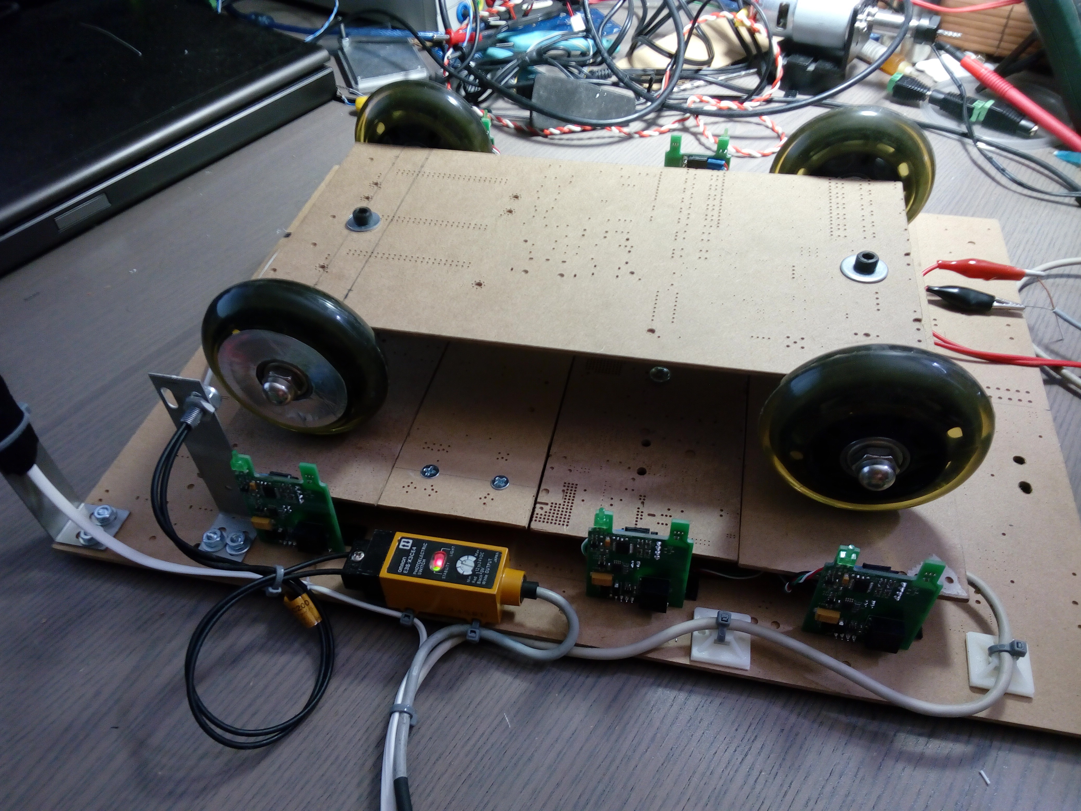
It's time to do a test setup for 3 axle truck weight measurement.
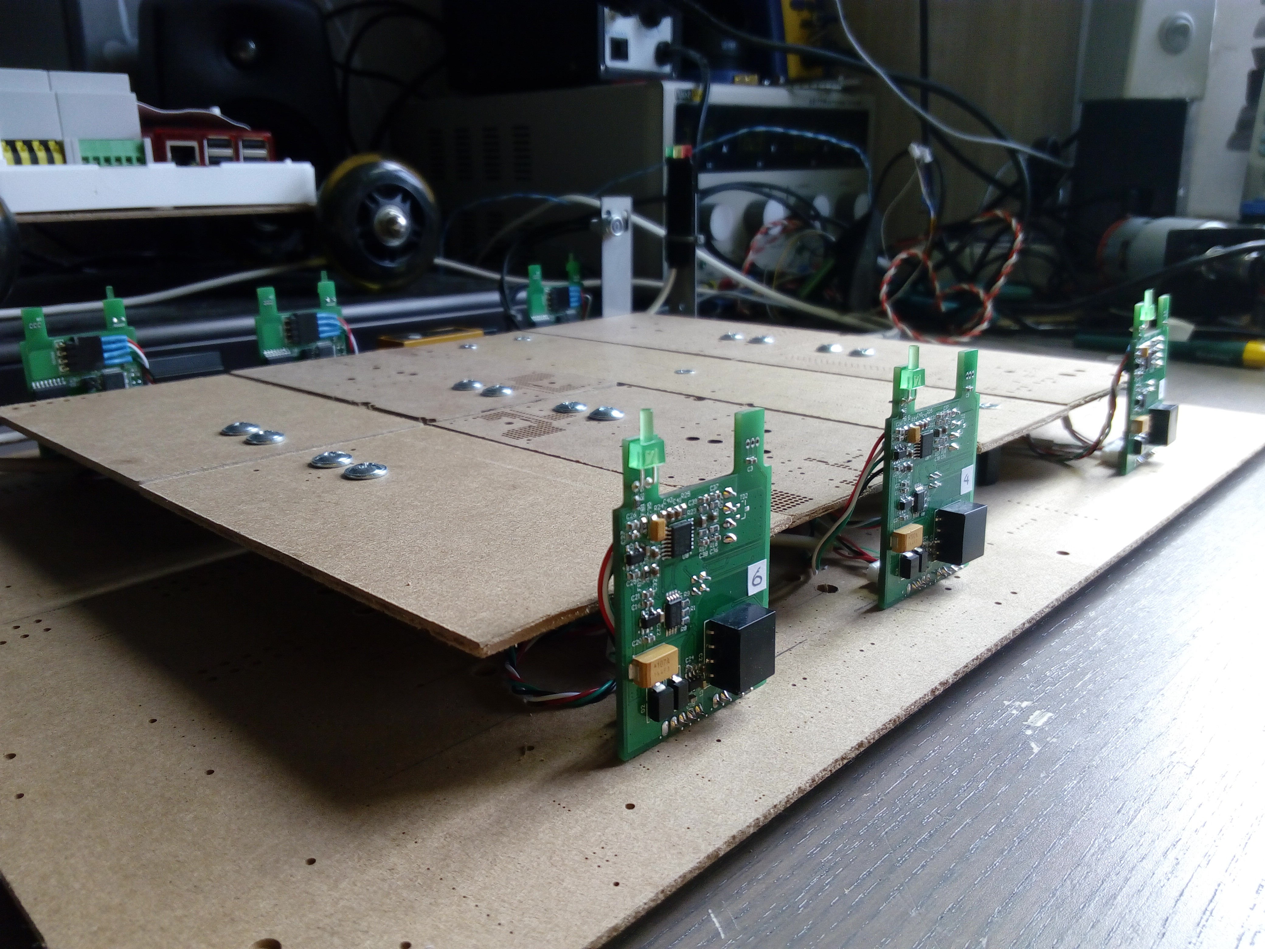
Don't ask me, why I used this ugly carton (I received it as a package for SMD stencils from my Chinese PCB fab), while I have unlimited access to laser cut and water-jet cutter CNC. I could do it from any material like glass, stainless steel or titanium. Let's call it "ECO".
Luckily this carton was very good material for this setup. Easy to cut, and has some flexibility, so I don't need to add any suspension for my trolley (truck model).
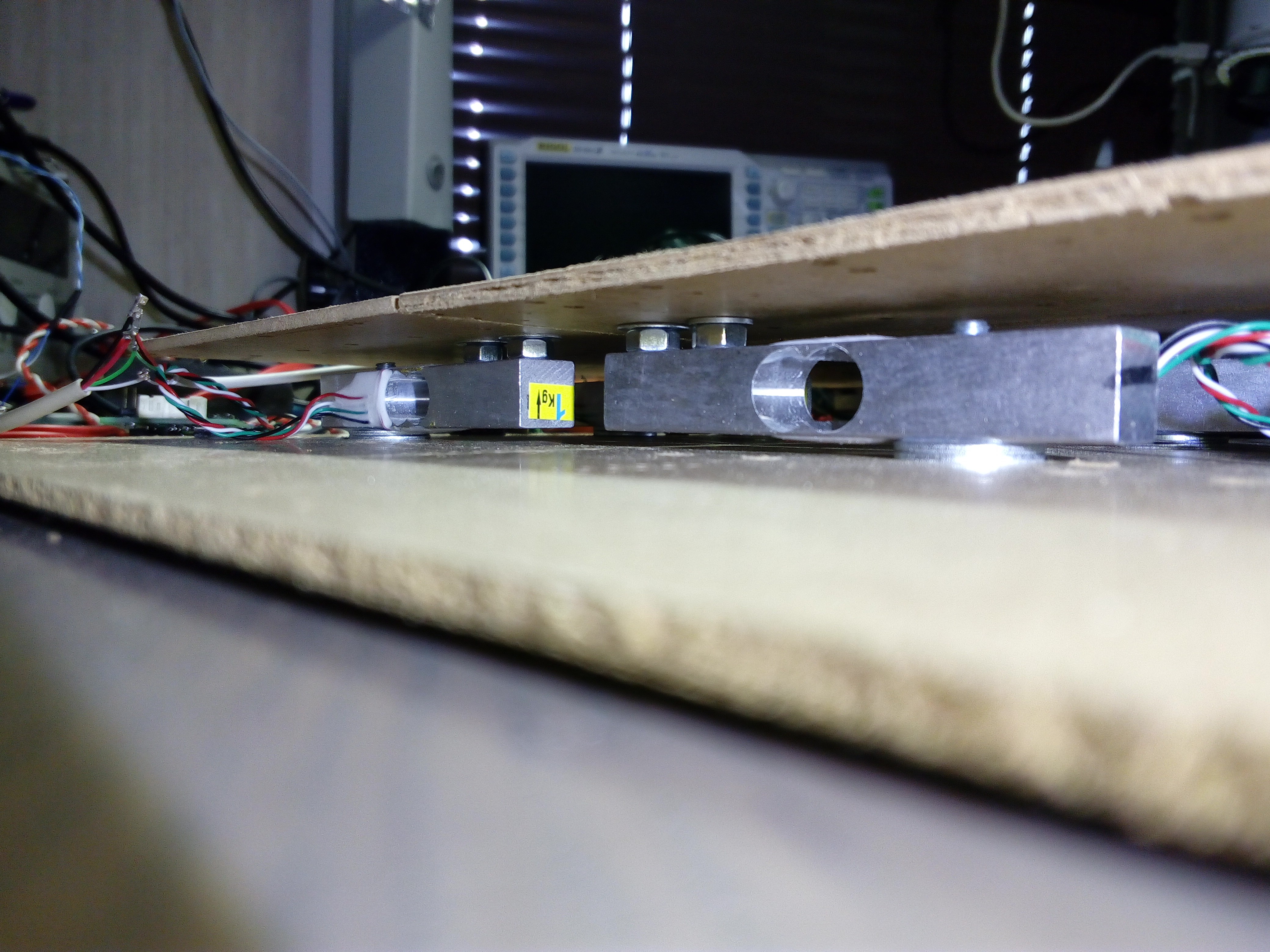
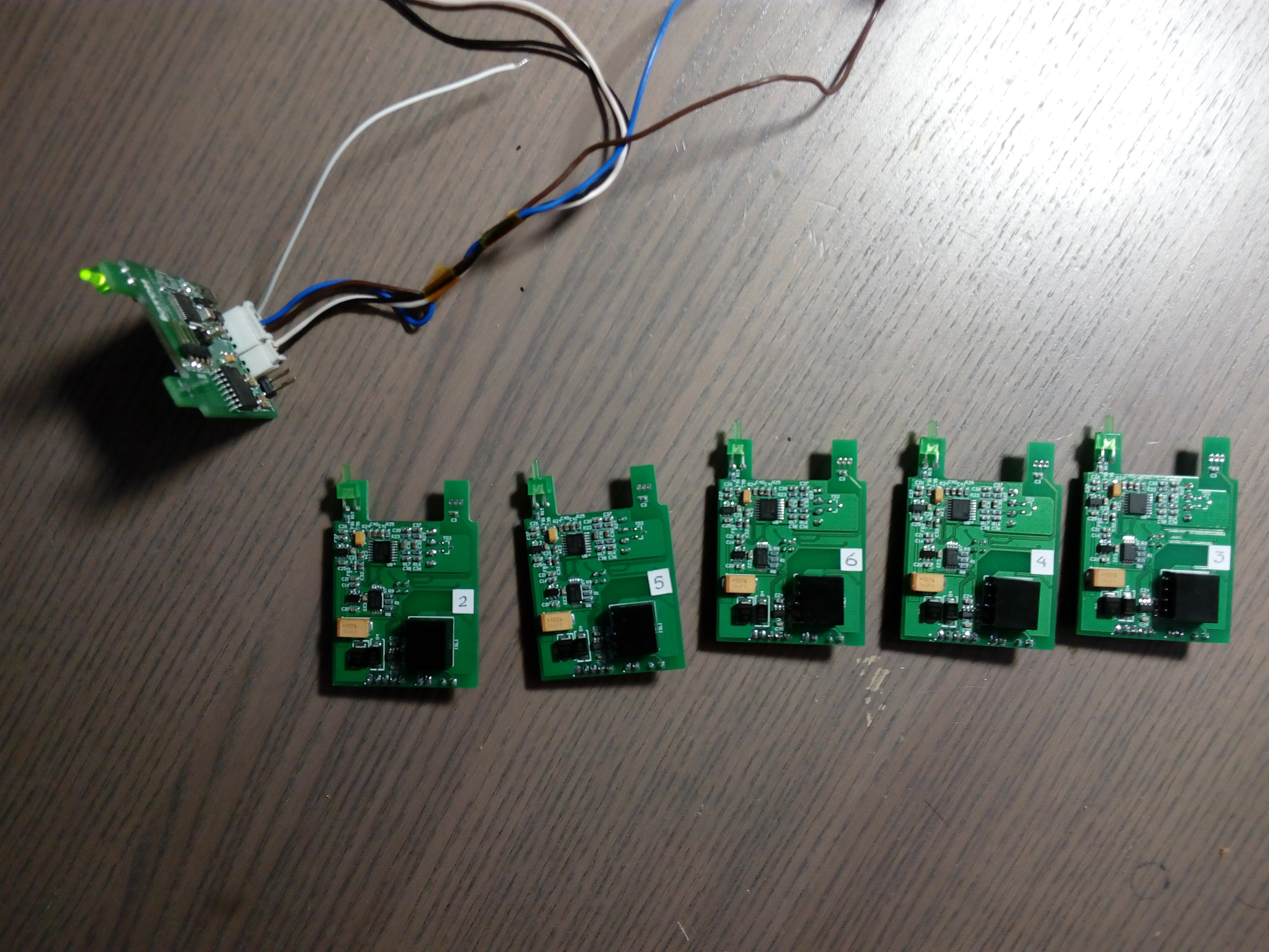
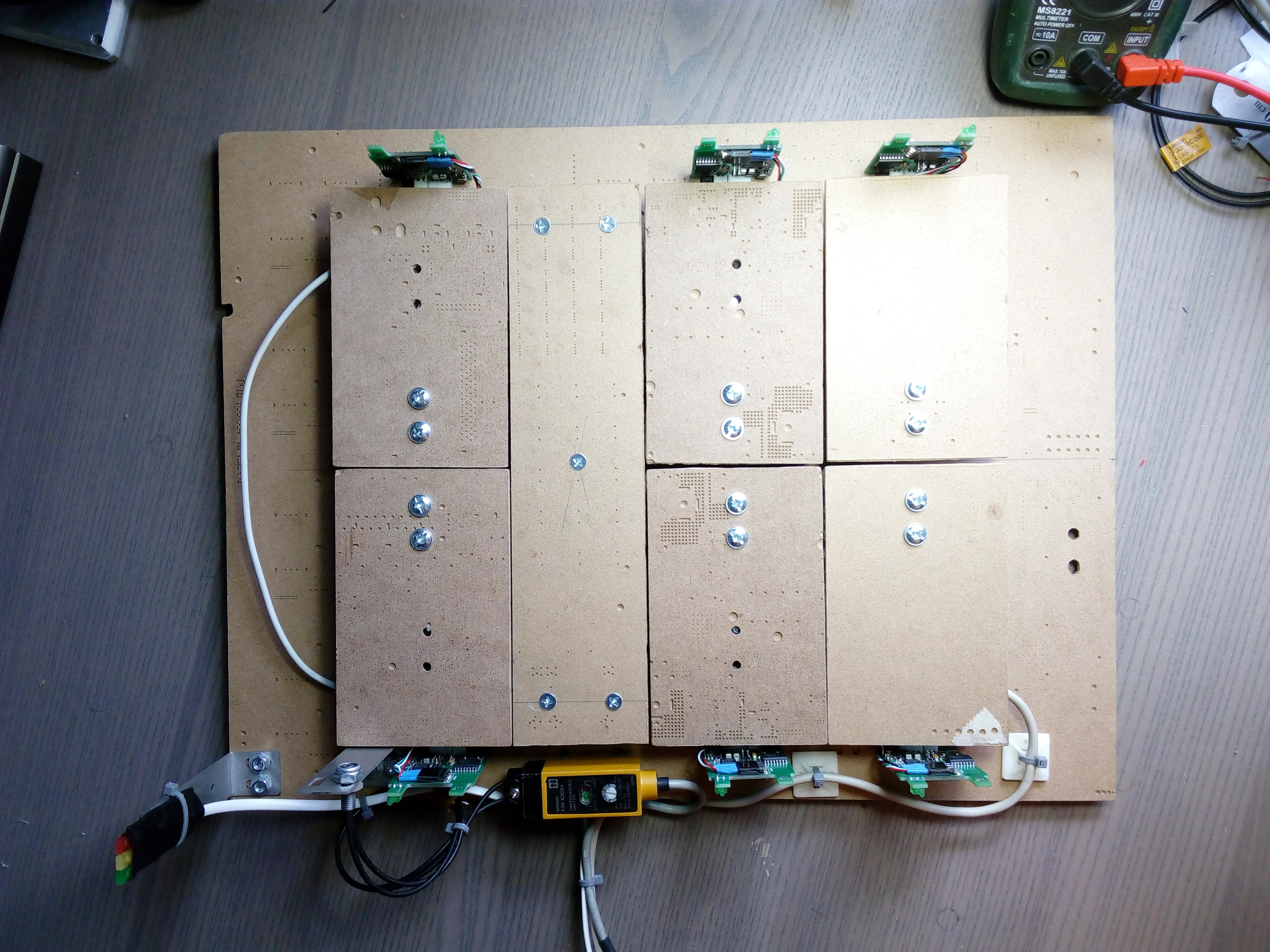
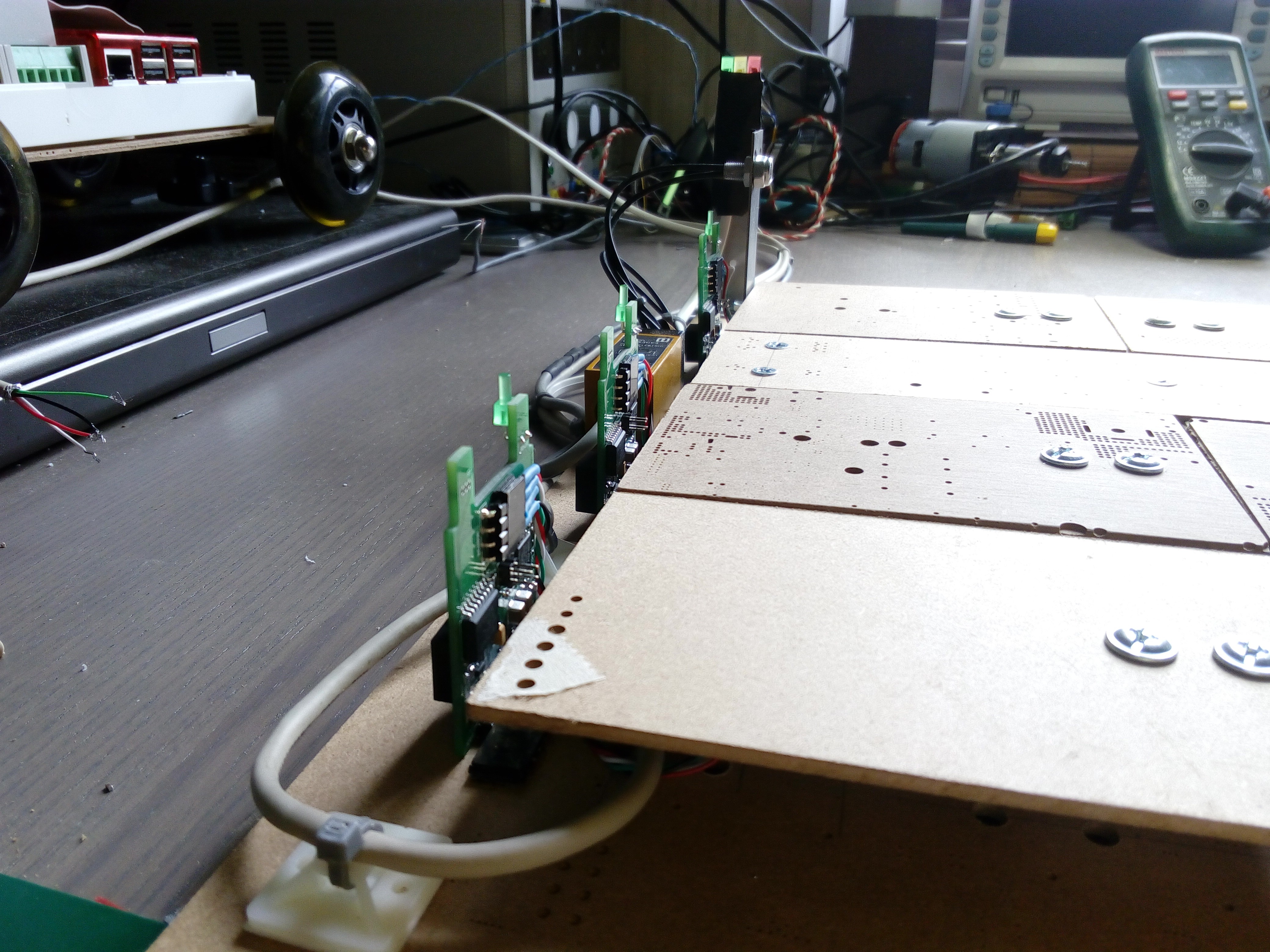
At first, I fixed 6 load cells by bolts to the base and fixed load plates. It's bad quality Chinese load cells, but it's enough tor the test reasons.

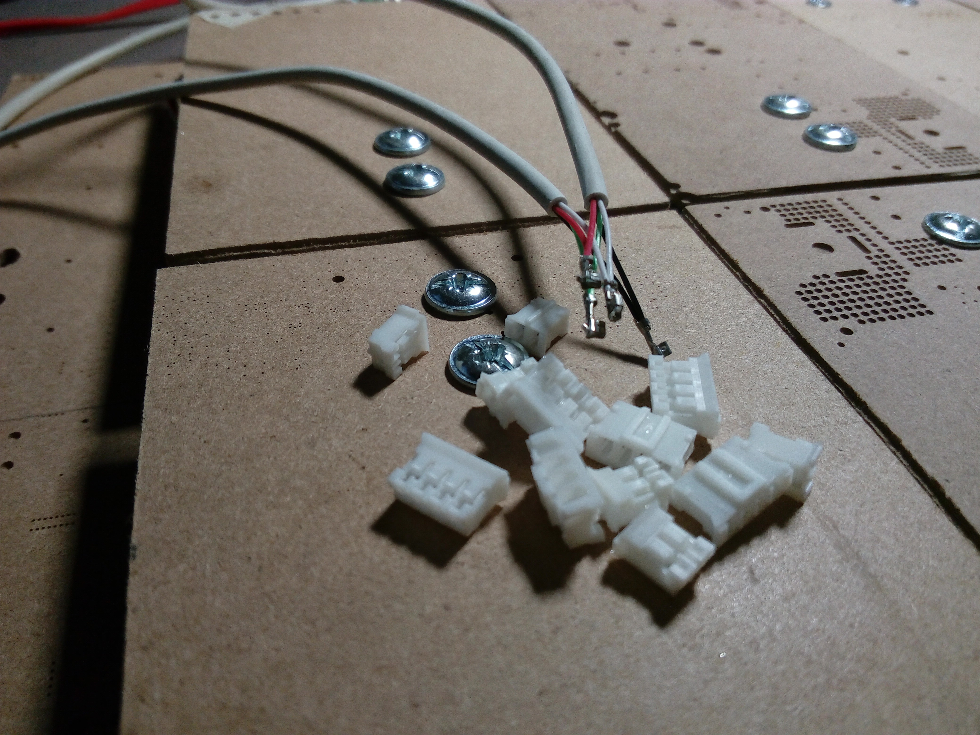
Next, I placed 6 Load cell - Modbus PCBs around, cut cables in length, crimping connector sockets and assembled the connectors.
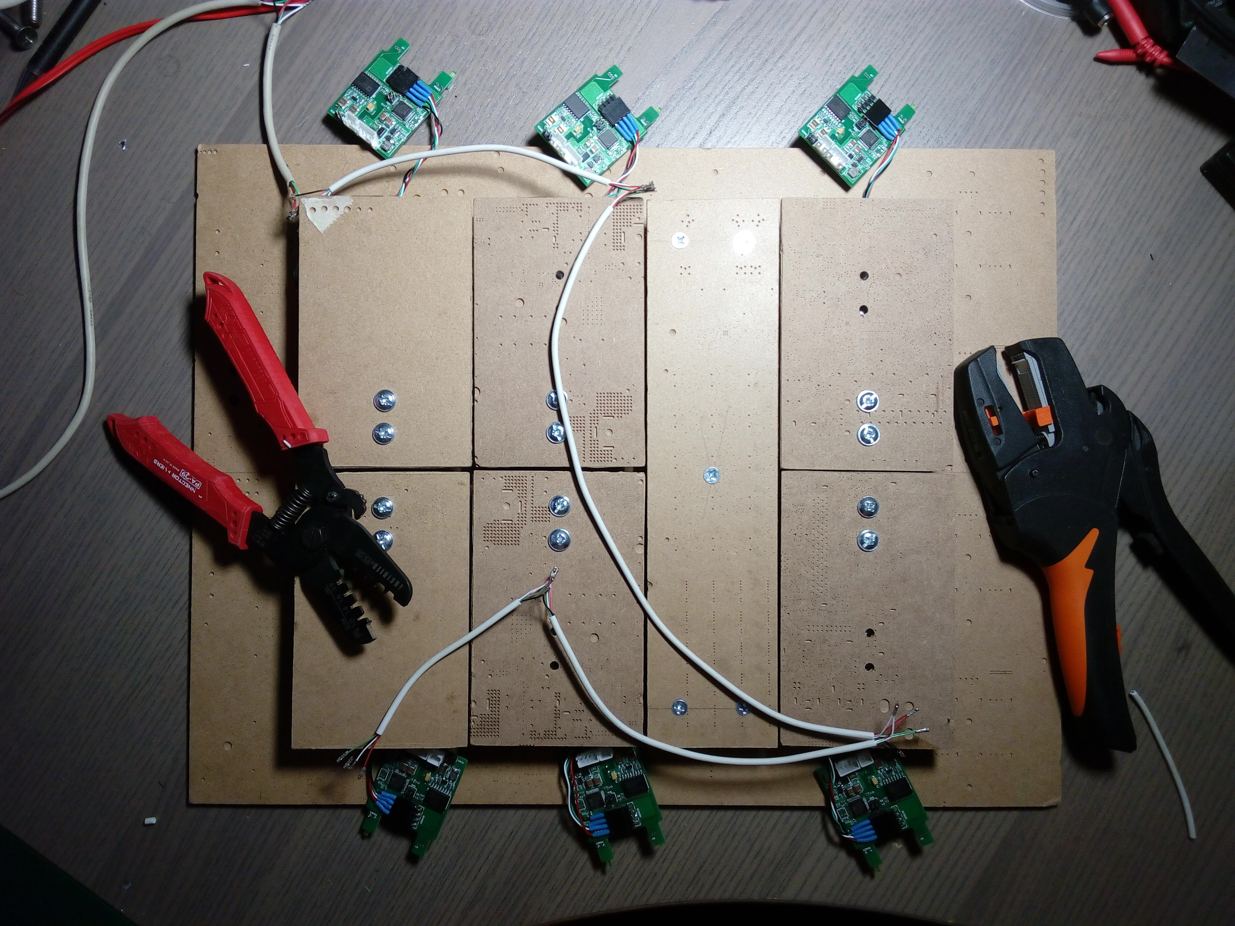
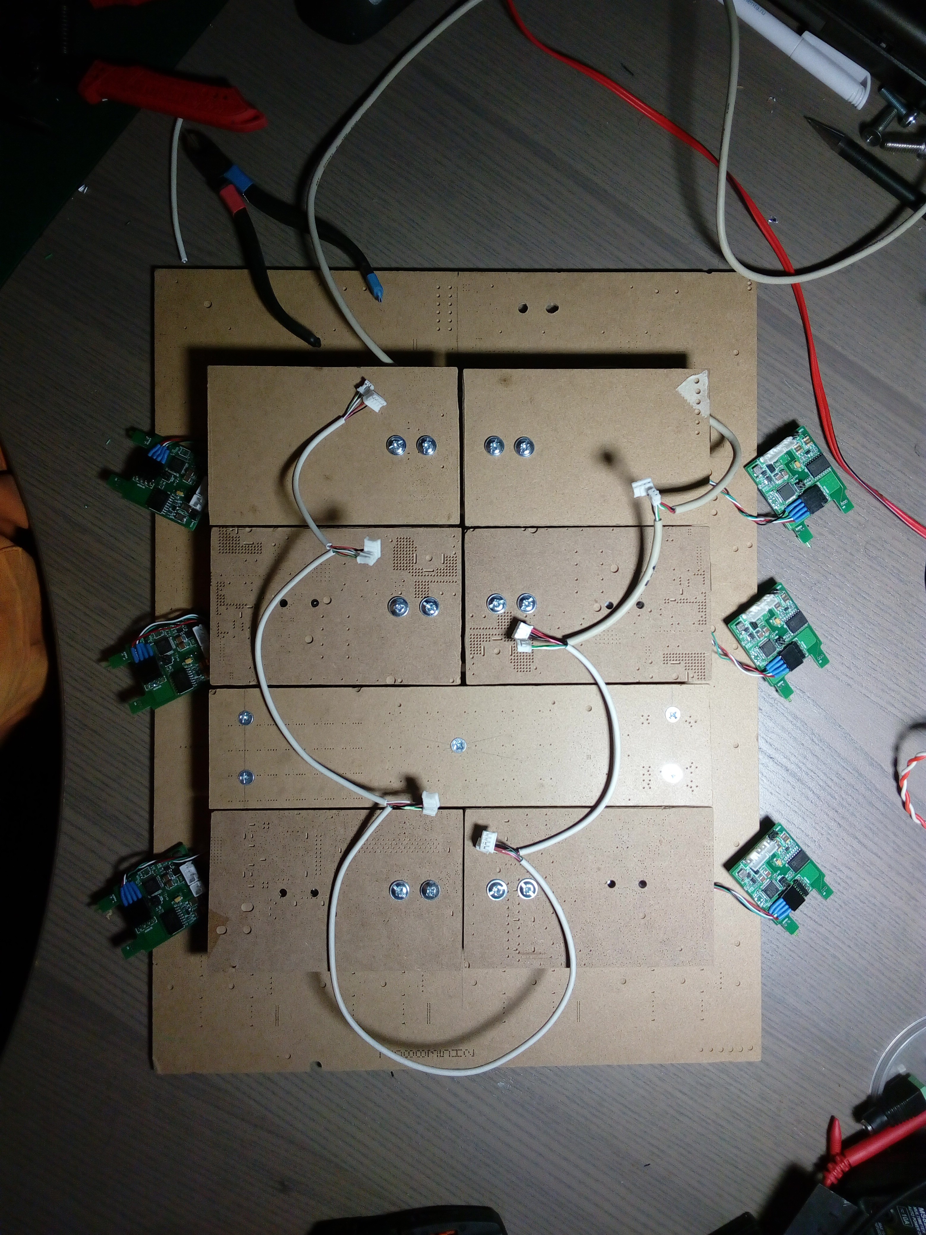
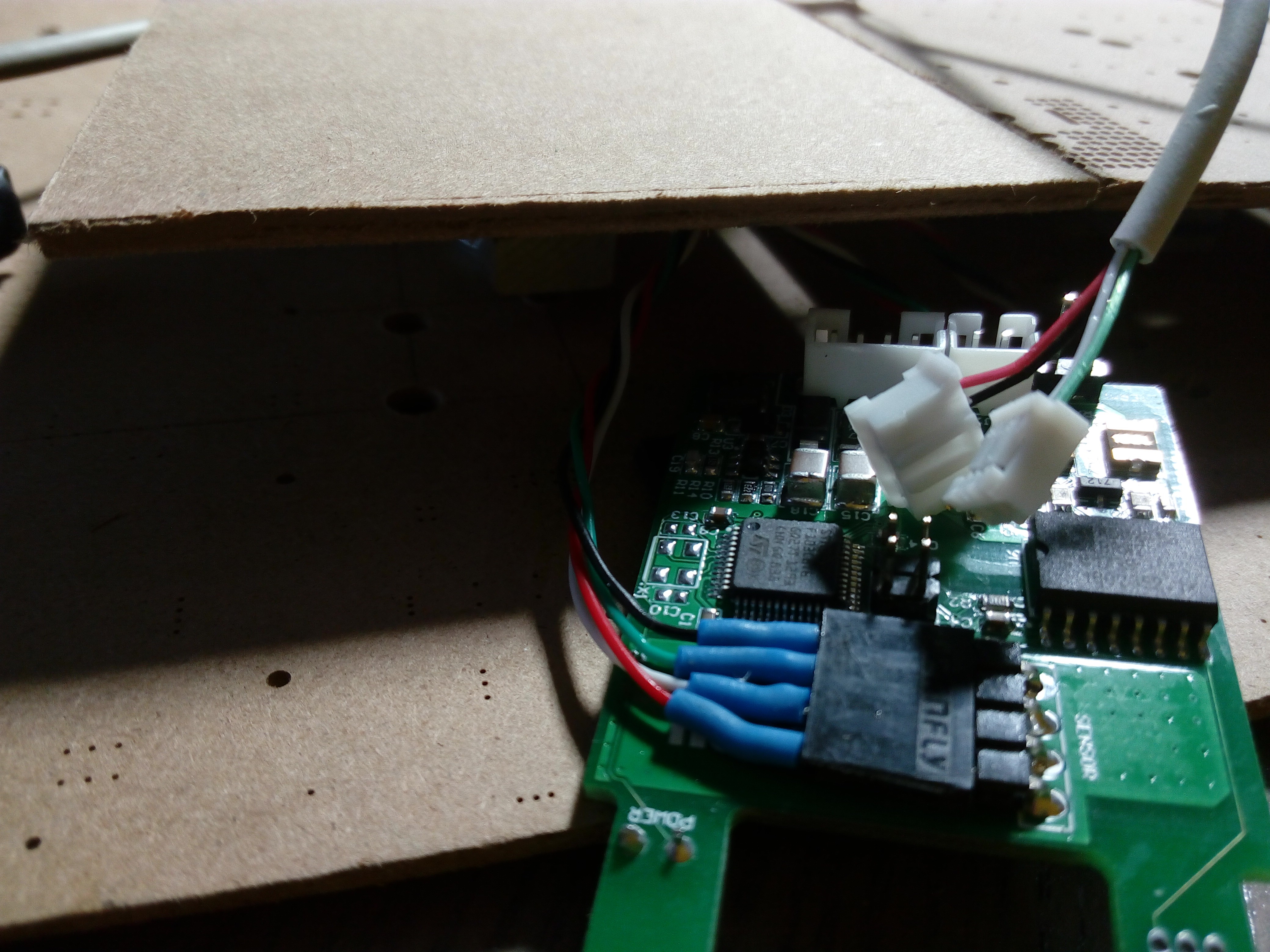
Pay attention to the tool with red handles! I think it's the world best solution for low mass connector crimping. If you are interested in a manufacturer, just ask me.
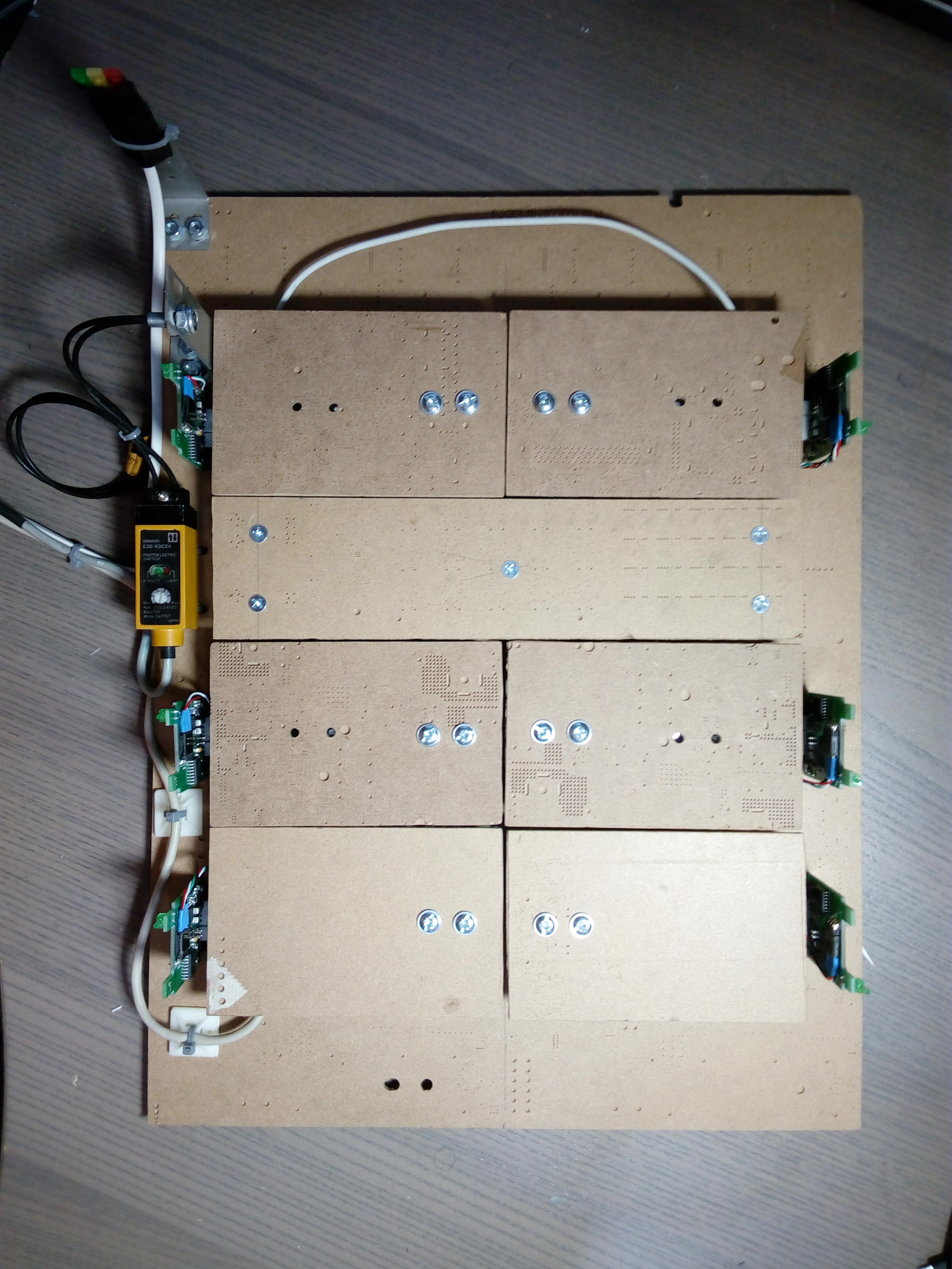
Next, I placed the boards vertically to see the LEDs.

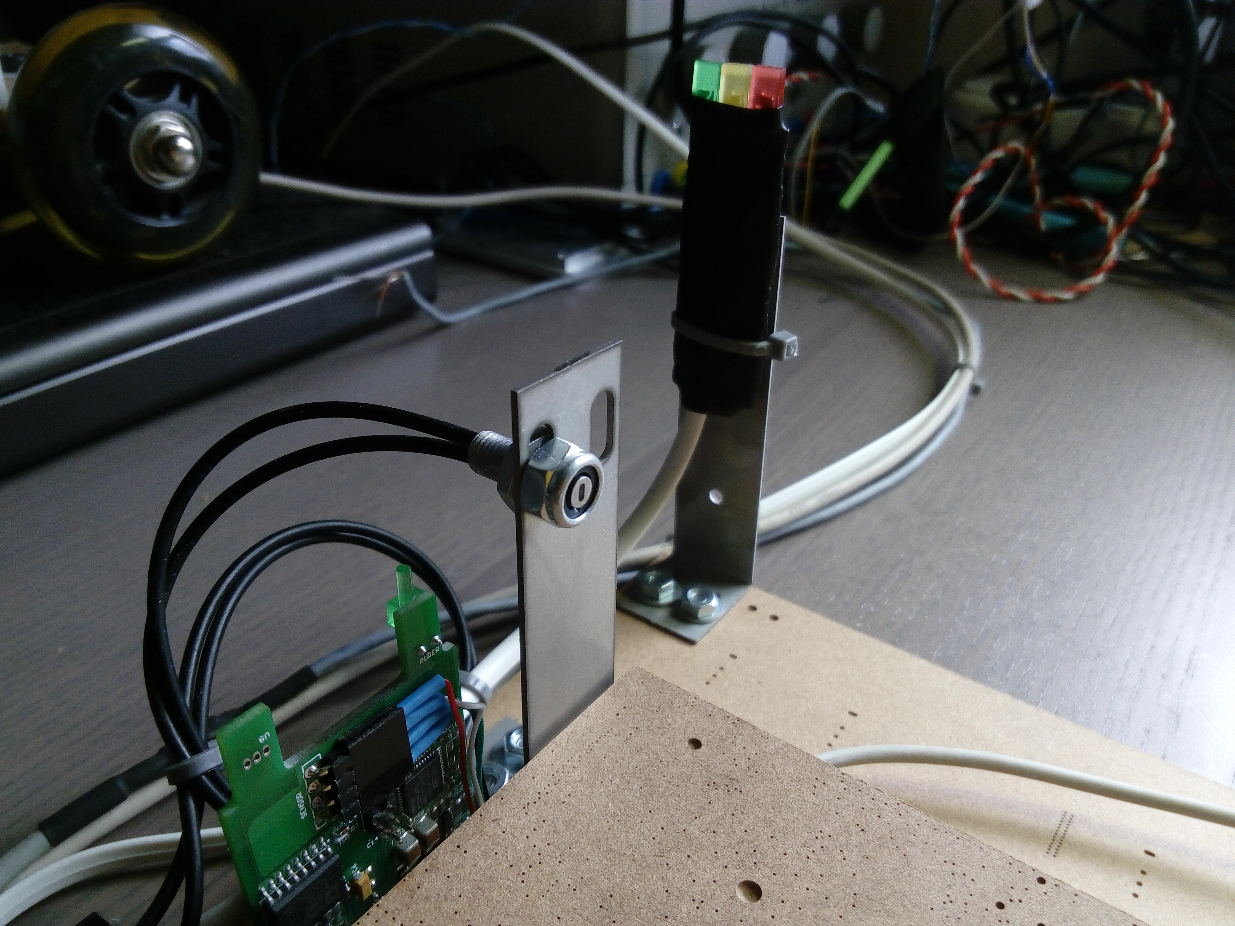
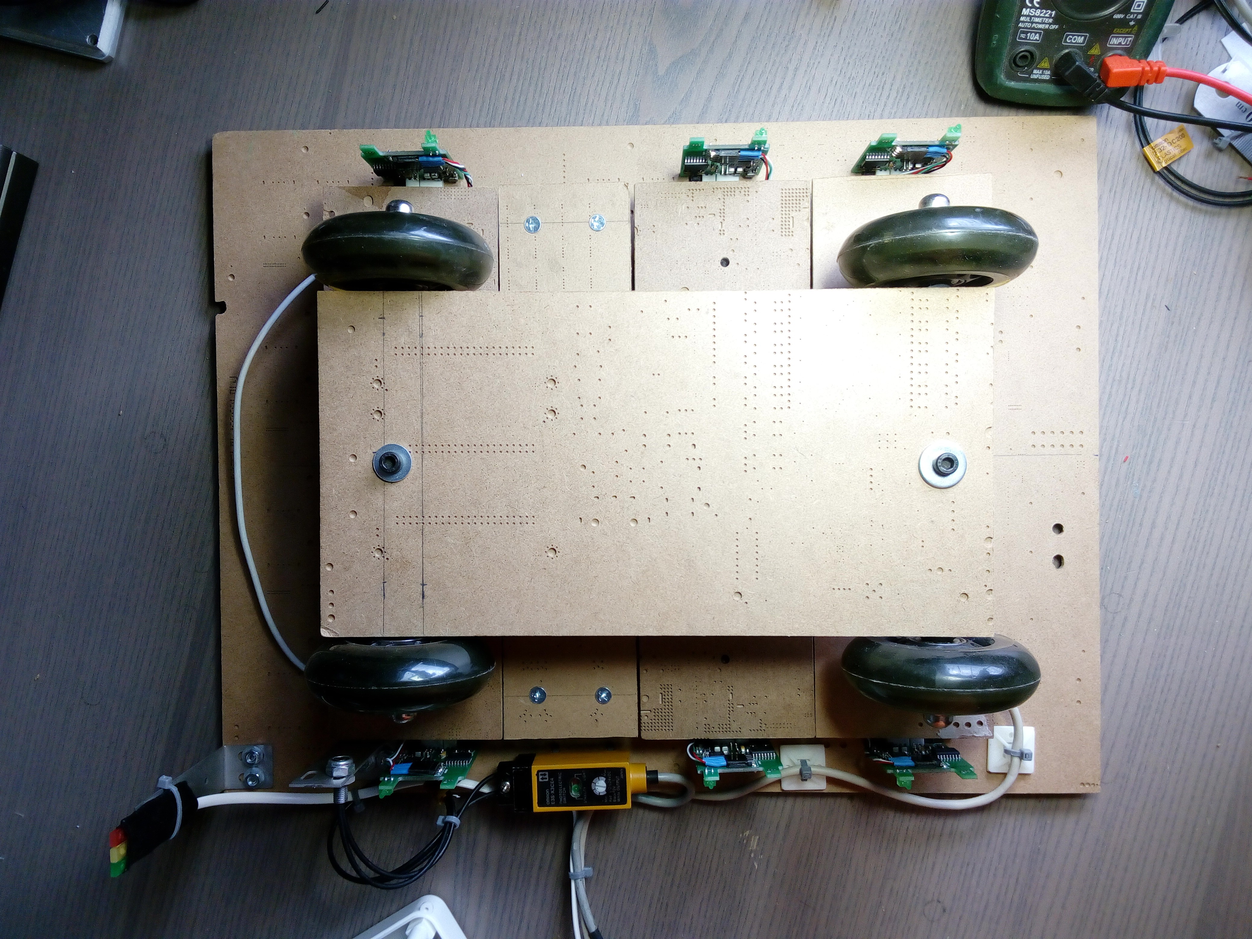
Placed led lights and OMRON distance sensor.
It's time to program Modbus addresses to Load cell - Modbus interfaces. I used MbPoll software and addresses from 1 to 6.
Some additional pics:
With trolley:
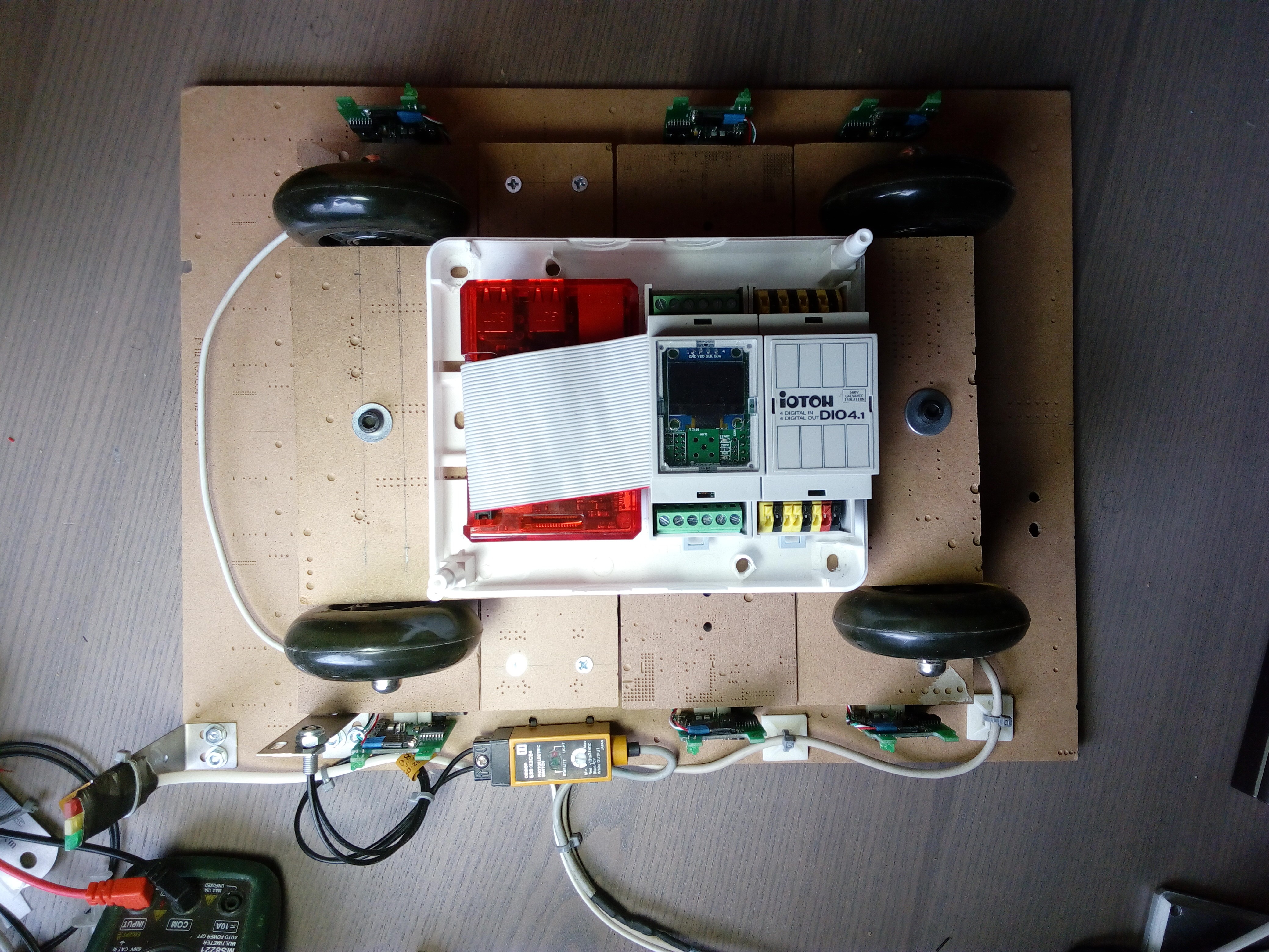
With PI-FACE and DIO4 module:
...
Discussions
Become a Hackaday.io Member
Create an account to leave a comment. Already have an account? Log In.
There are many vehicles in the world and from them the most incredible invention is three wheel axel vehicle and this https://bestwritingclues.com/reviews/essay-company-review/ share quality work. This post is telling about all the measurements they will take before the test of this vehicle.
Are you sure? yes | no