 Electroniclovers123
➢Step descriptions:
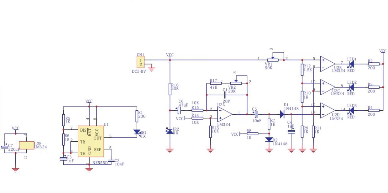
✦Step 1:-This is the circuit diagram.
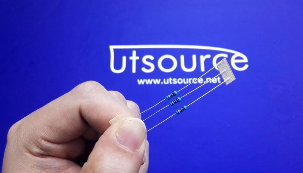
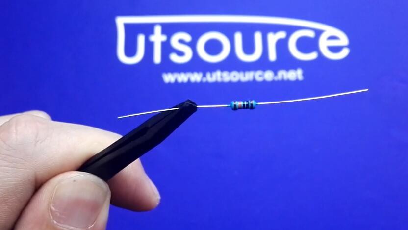
✦Step 2:- first, solder the 10 resistors 3pcs,

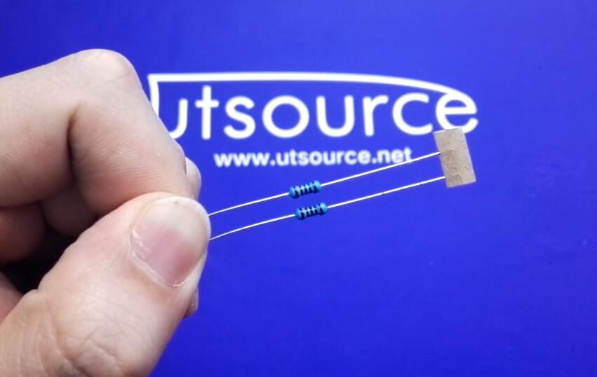
✦Step 3:-Then solder the 1k resistors 2pcs

✦Step 4:-Solder the 10 resistor 1 piece.
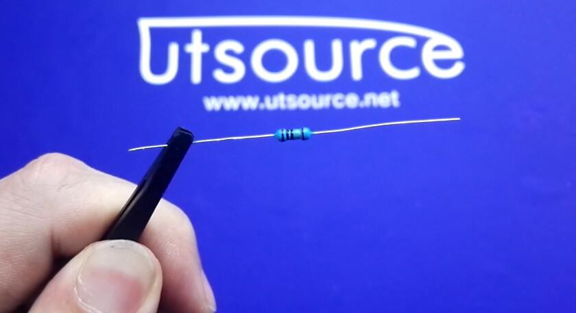
✦Step 5:-.Solder the 1M resistor 1 piece.
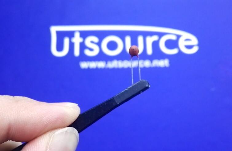
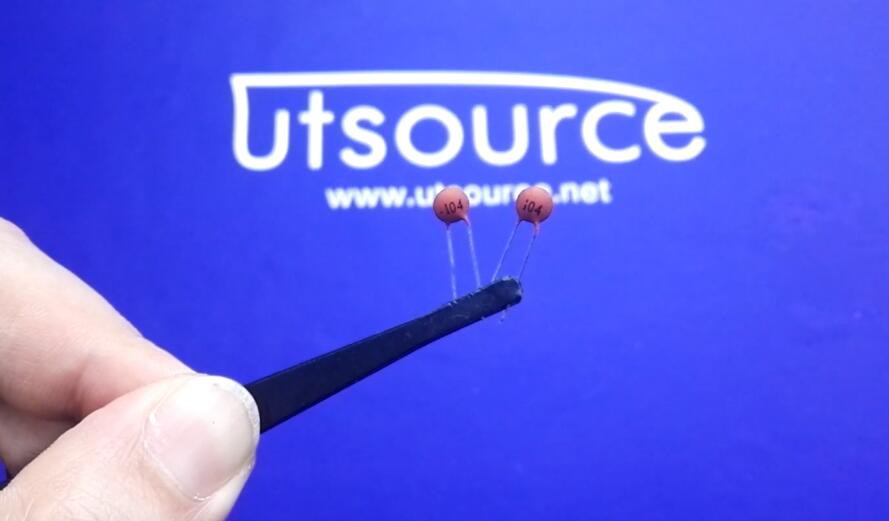
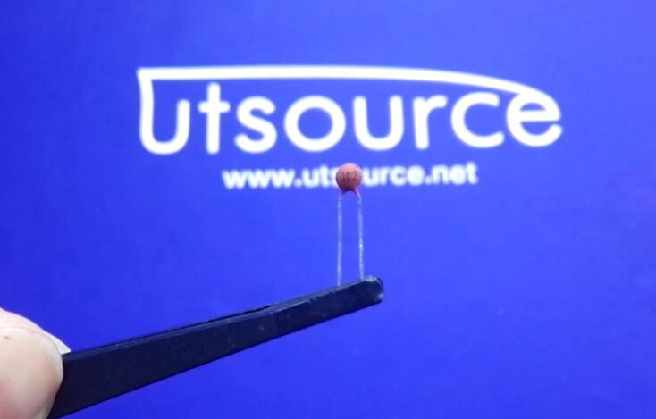
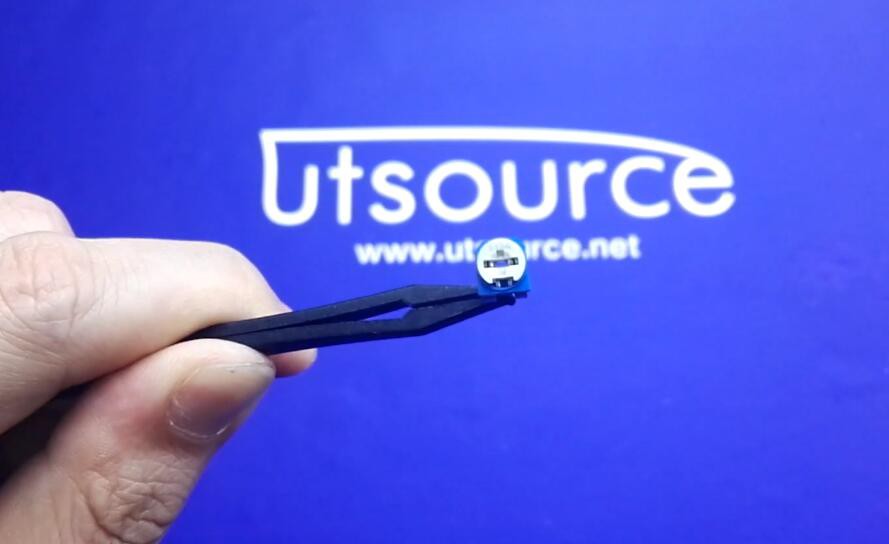
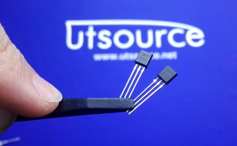
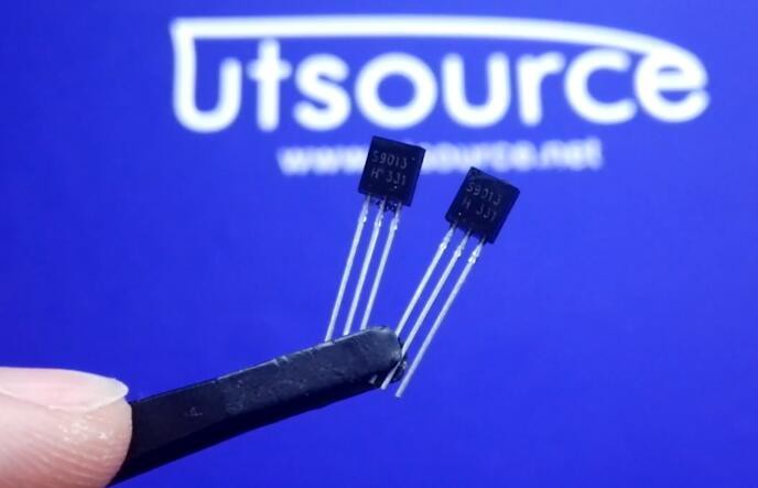
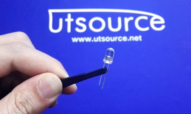
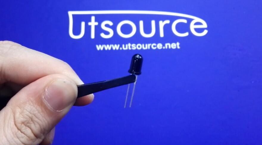
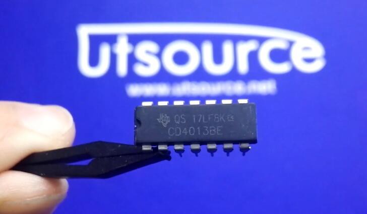
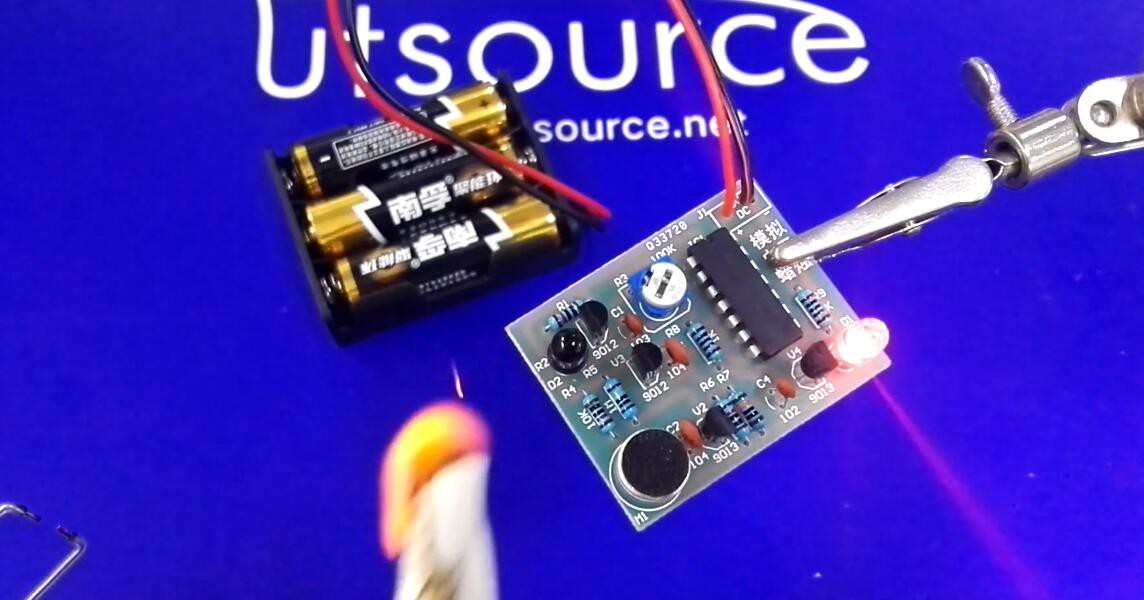
✦Step 6:-Solder the 103 ceramic capacitor 1 piece, 104 ceramic capacitor 2pcs, 102 ceramic capacitor 1 piece, adjustable potentiometer, 9012 transistor 2pcs, 9013 transistor 2pcs, pickup microphone, white led with red light, black infrared receiver diode, CD4013.

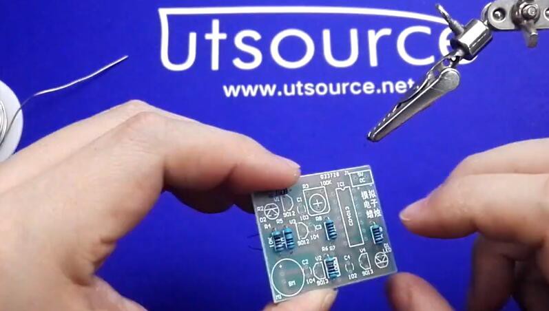
✦Step 7:-.Finish it and connect the power supply to have a test.
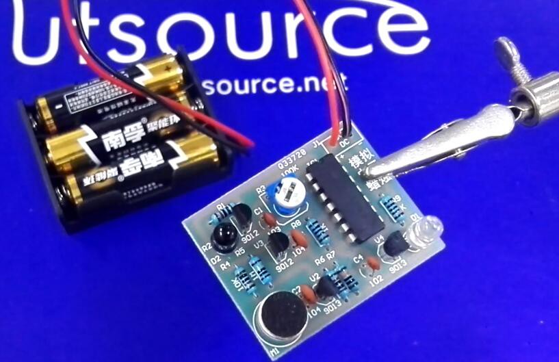
✦Step 8:-When the flame is close to the electronic candle, the led is on, when blowing the the candle, the led will be off, it is like a real candle.
Product list:
『10K resistor 』 view more ⇒ https://www.utsource.net/sch/10K%20resistor
『1K resistor 』view more ⇒https://www.utsource.net/sch/1K%20resistor
『1M resistor 』1M resistor view more ⇒ https://www.utsource.net/sch/1M%20resistor
『Adjustable potentiometer 』 view more ⇒ https://www.utsource.net/sch/Adjustable%20potentiometer
『9012 Transistor 』 view more ⇒ https://www.utsource.net/sch/9012%20Transistor
『9013 Transistor 』 view more ⇒ https://www.utsource.net/sch/9013%20Transistor
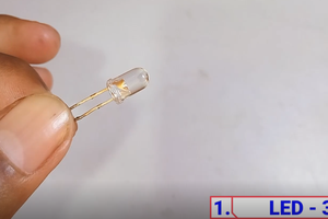
『White LED with red light 』 view more ⇒ https://www.utsource.net/sch/LED%20%20red%20light
『CD4013 』 view more ⇒https://www.utsource.net/sch/CD4013
Video on Youtube:

The diagram on top is from a different project, please change it.