 Dillon Nichols
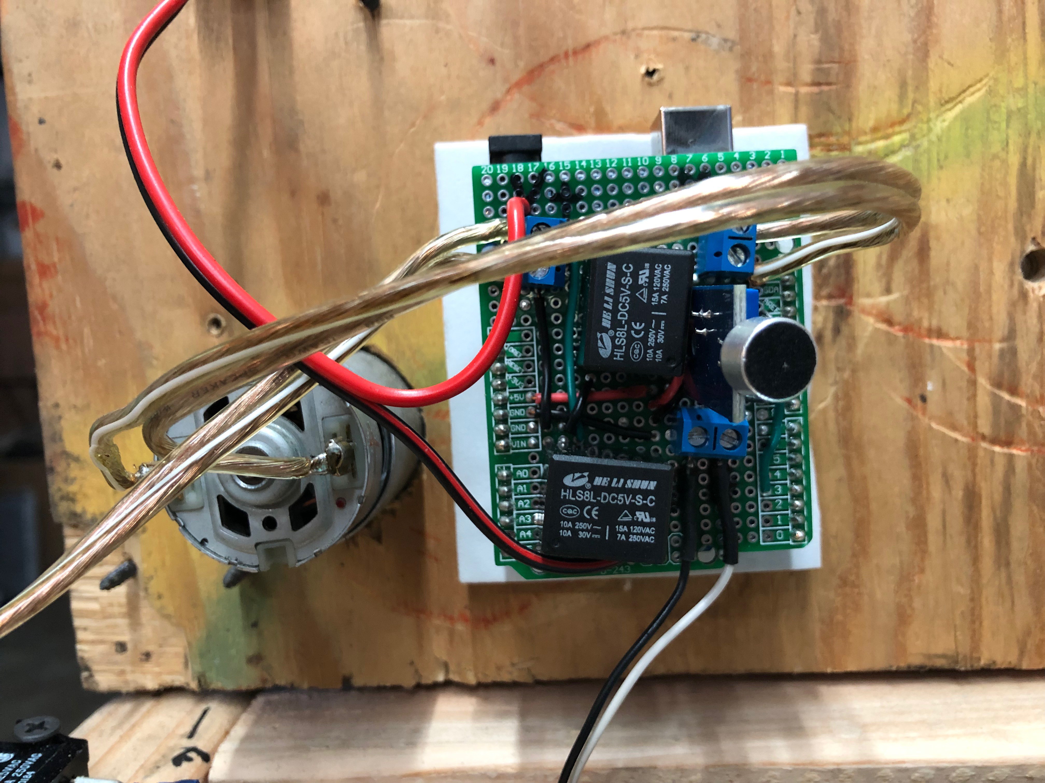
As mentioned in the description, the electronics are mainly an Arduino Uno with a homemade shield. The end result is fairly simple but it took quite a bit of effort to get to that point.
I began by controlling the motor with my 30A adjustable power supply. I found that about 10V provided some good torque but it still spun too fast. I found a small DC motor driver but it couldn’t handle the motor’s current. First the flyback diode exploded and I replaced it with something beefier. After that, It worked,but the whole PCB was smoking. I had to find a new idea.
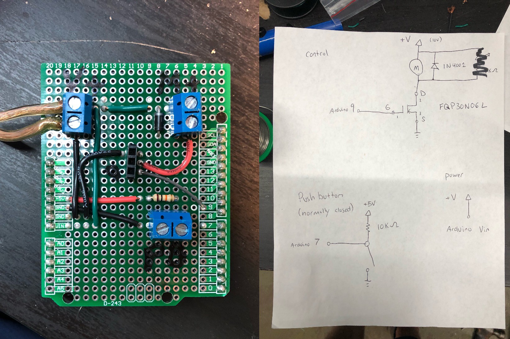
At this point, I decided that I needed to start and stop the motor to add a delay between claps so I knew I’d need a microcontroller. For rapid prototyping simple ideas like this, you can’t beat an Arduino, so I used a protoboard shield and built my circuit up. This first version had motor voltage in (10-12V) that also powered the Arduino via the Vin pin and a logic level MOSFET (FQP30N06L) and flyback diode to control the motor which is connected via another screw terminal. I also added another connector for a switch that can be used to detect the position of the cam and stop it after one revolution.
I had a lot of issues with this circuit, but I eventually gave in and replaced the MOSFET with a relay. I didn’t use a relay at first because I was worried that it would be too loud, but it is silent compared to the overall mechanism (Rue Mohr did provide a circuit on Twitter if you want a solid state alternative). I rebuilt the shield with the relay soldered in place and it works well now. I should mention that I had a lot of troubles with the relay “welding” itself on. This seems to be a problem when too much current goes through the relay and the arc welds it shut. I read that one way to fix it is to just let it happen over and over again until the pads are built up and it won't happen anymore. This either fixed it or the better power supply did.
The next task was controlling the Applause light. This one uses another of the same type of relay that the motor uses. I turn the light on when the clapping is detected and turn it off after the whole process is complete.

I actually bought an official Clapper to use for this project, but it doesn’t work with how much noise the machine makes. The Clapper has to have proper timing between claps with silence and a period of silence afterwards that my machine can’t make. I knew I needed to make my own clap detection circuit so I searched for a few different options. The first one I tried is a M5StickC with a built-in MEMS microphone. I chose this because it was battery powered and I thought I could just turn on the power supply when it detects a clap and it would automatically run. Unfortunately, the microphone’s communication seemed too slow to detect the sharp sound pulse of a clap. There may be a method to make this work but I didn’t want to become an expert on the SPM1423HM4H-B microphone and I2S communication ust to detect a clap. The next option was a basic microphone breakout that took power in and gave a digital output when noise was detected. I set the threshold of the onboard potentiometer and originally put a capacitor from the output pin to smooth out some noise and it worked perfectly as a trigger. I removed the capacitor when I changed the pin to an interrupt because I only cared about the first pulse. The rest could be done in code.
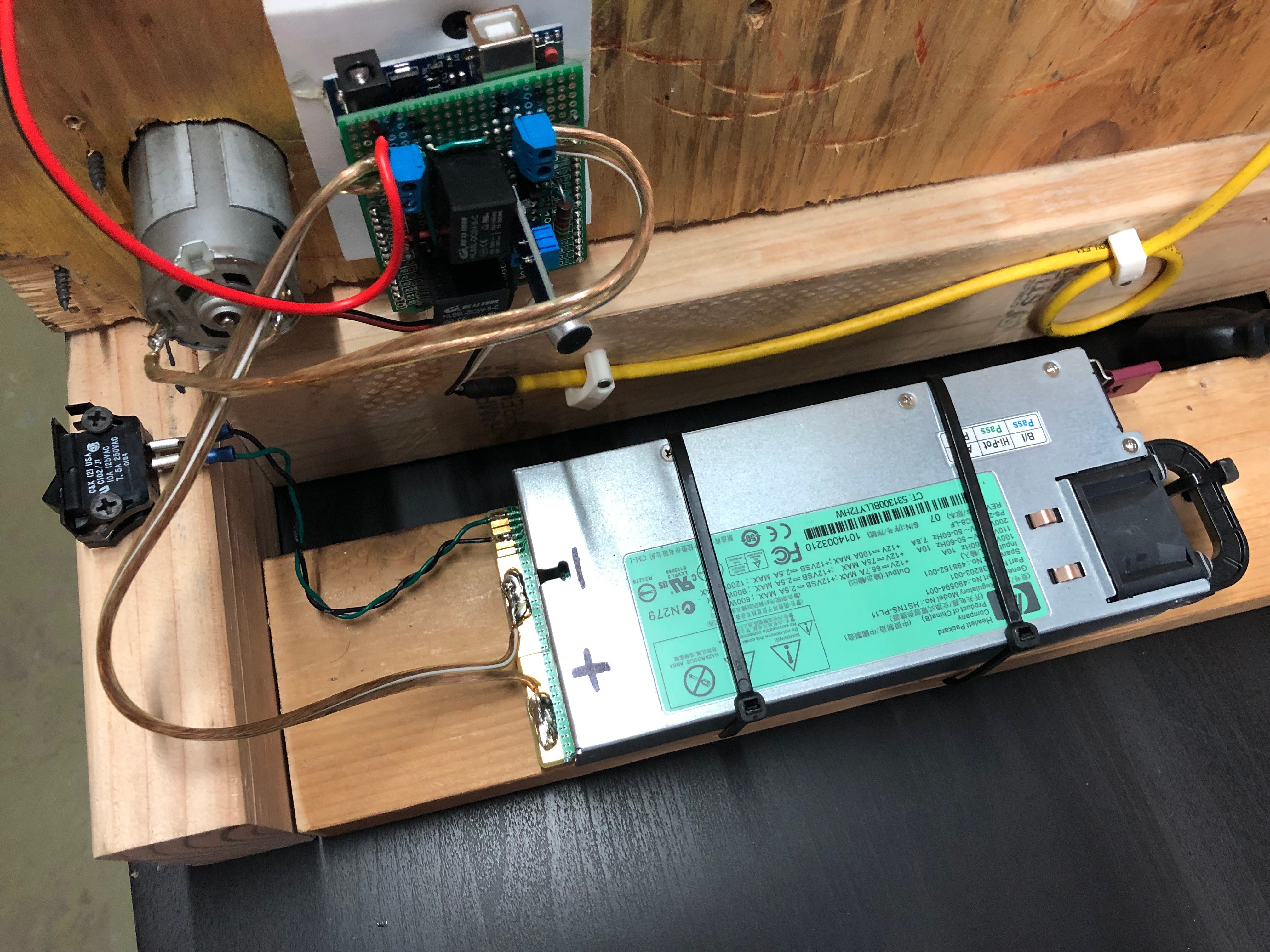
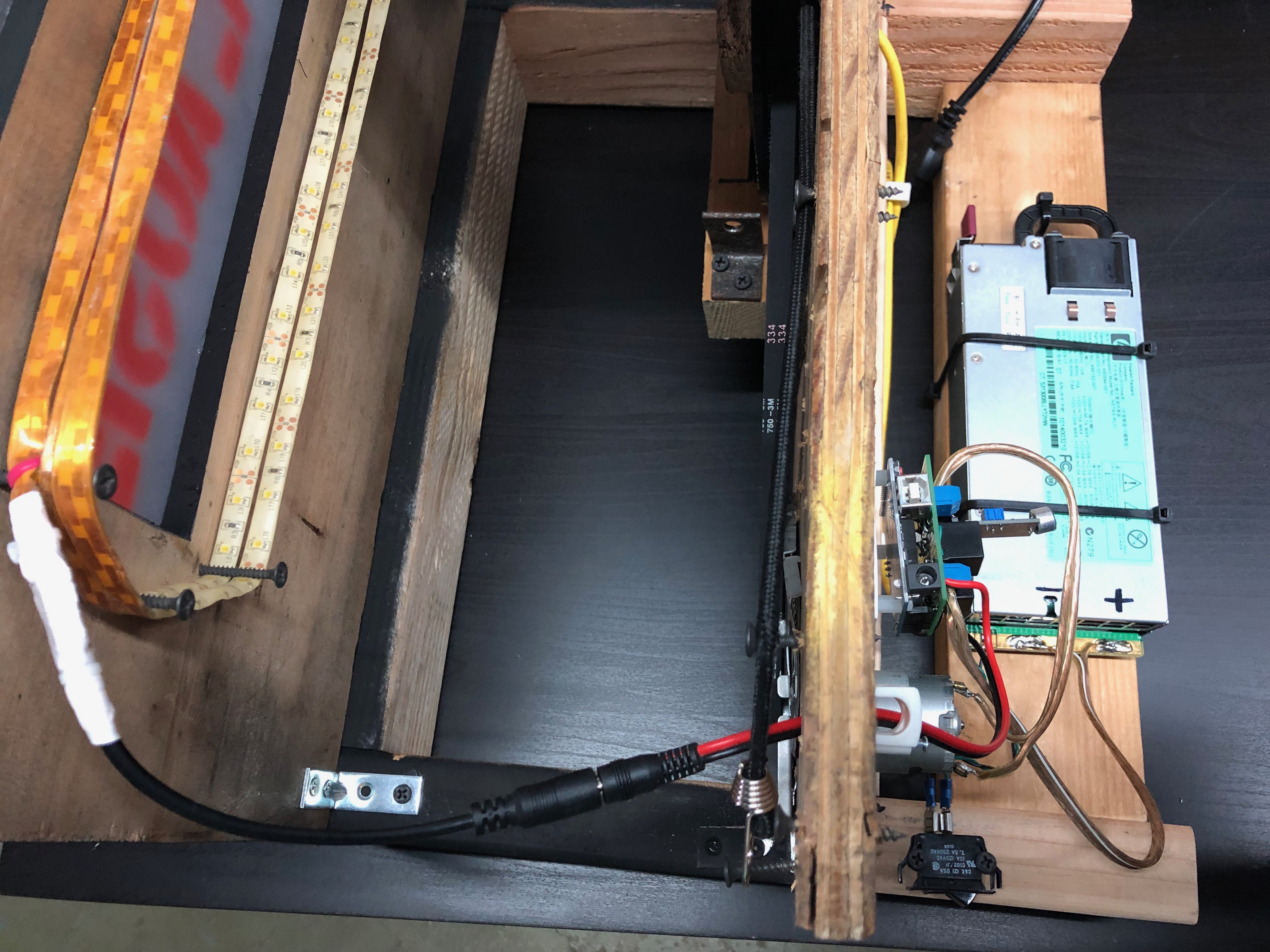
Now that the system was working as a whole, I noticed that my 30A bench power supply couldn’t keep up to the motor’s current draw. It would brown out when the motor turned on which was obvious looking at the applause light, but would also sometimes even get low enough to reset the Arduino and then the clapping would never stop. I went searching on Mouser for another power supply but 12V supplies with >30A current are super expensive. The cheapest option I found was about $50. My next step was to turn to eBay, where I found this project’s saving grace… server power supplies. They have stable 12V supplies and huge power budgets. The one in particular that I bought is a HP Server PSU HSTNS-PL11 1200W but I found that the HP 506821-001 ProLiant 750W is also very popular. After some research, I found the connections to enable the main 12V supply. I added a switch to the enable line so I could easily turn the power on and off when I wanted without unplugging it. Apparently server power supplies like this are popular in the RC car and plane community to quickly recharge batteries. Anyways, After I got this power supply, the issue with the Arduino dropping out went away. You can still see the lights dim when the motor spins but it isn’t as bad as before.
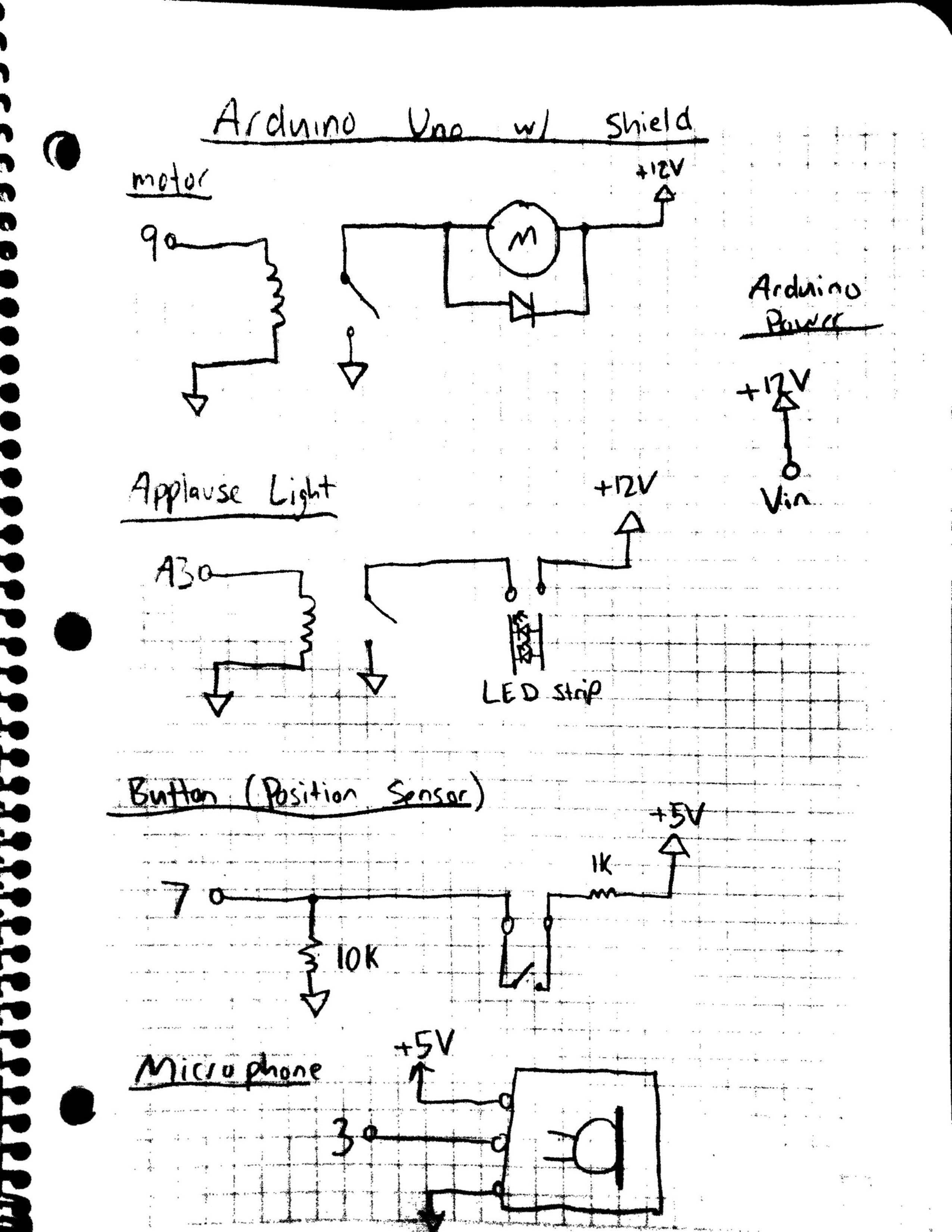
Here's the final schematic for the shield wiring.
This post is long enough so I’ll briefly cover the code in the next log.
Discussions
Become a Hackaday.io Member
Create an account to leave a comment. Already have an account? Log In.