-
Version 2 is almost done!
02/23/2017 at 22:06 • 0 commentsHi everyone, I made a lot of progress since the last log. I worked on the Curve tracer like almost every day around 2-3 hours.
It is more complex then I thought in the past, it will be. Now it is sort of working, with some function.
What is working:
- I can change the voltage range between around 40Vpp - 0.5Vpp in 25 steps.
- I can change the frequency between 170Hz and 1.1kHz in 6 steps.
- It is working from the main now, but if I want I can program the microcontroller at the same time.
What does not work yet:
- I can use only one resistance range at this moment, but I am working on it. It will have 15 resistance range at the end.
- The automatic voltage level stabiliser, which will adjust the lines to the maximum screen size, when you change the voltage range.
- I need to finnish the main sreen (the big one).
- I have to fix some bug.
- The alternating mode is not finnished yet. (second channel)
- And some little stuff.
And the video ;)
-
Sine wave generator test
02/05/2017 at 17:45 • 1 commentRecently I had not too much progress on the V2, but on this weekend I made one of the main part of the curve tracer, which is the sine wave generator. On the Version 1, I did it with a simple solution, with a transformer, which give me 12V 50Hz sine wave. It was good for basic things, but if you would like to measure electronic components with series or parallel with inductance or capacitans, you have to use higher frequancy. At higher frequancy inductive and capacitive parts shoud act differently.
This is the reason, because you have to use a variable frequancy source, to drive your front end electronic. I would like to have 6 or more steps on the frequancy range like the minimum is around 50 (60)Hz and the maximum is up to 1.5 - 2kHz.
As you can see in the video, I did managed to do the electronic, and it is more than capable to make the sine wave up to 10-20Khz, if have to.
I had some difficulty to set up the generator, because sadly I have not get an oscilloscope yet. So I had to do it differently, like I did on the Version 1, I modified the code to act like a simple oscilloscope, because if you think of it, a Curve tracer is a dual channel oscilloscope in X-Y mode, so the arduino is basically an oscilloscope in this project.
After all, I was able to develop one channel with it, so I will just have to copy the other channel from the first one and it is ready to go. It can measure a sine wave up to 1.5-2kHz so it is in the ideal range. (If I have to I will use some ADC accelerator code)
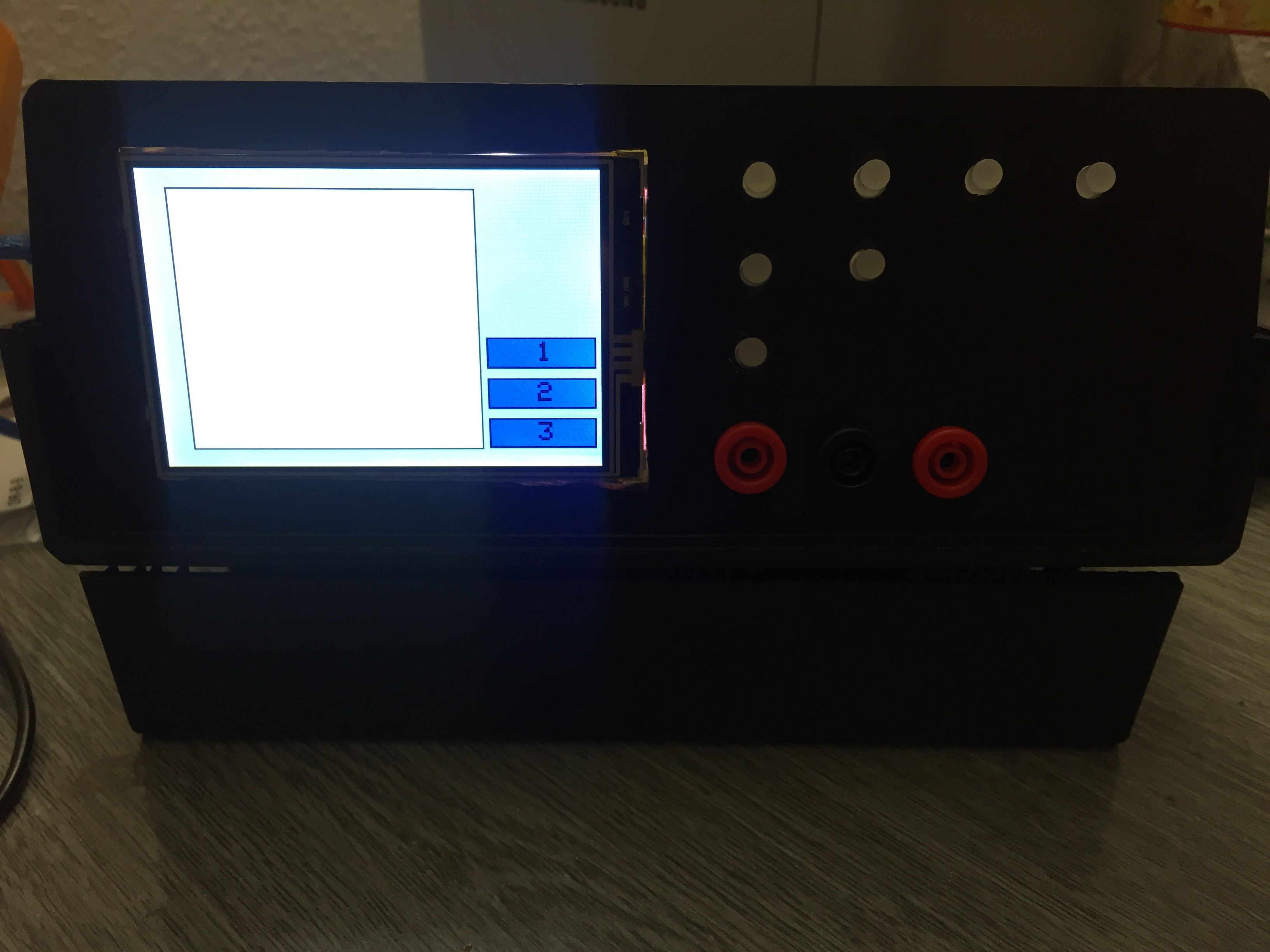
In the video the signal was free running, because I not use any trigger function. I programmed 2 main menu, which you see at the start, and that one where you can see and set the values for the Voltage, Resistance and to the Frequancy.
The left upper button is the menu button, the next to it is the Voltage selector button. When you selected a menu, it show you on the leds and on the screen which menu you ar in. The up and down button is light up that direction where you can set the value. Like if you are 0 on the voltage value it is only showing the up button with the led.
At this state where the project is, I have not figured out if I have to isolate the Arduino DUE (measure and contorl unit) from the sine wave generator completely or not, but I think I might be.
I also changed the code and now the display is smoother than before on the Version 1.
-
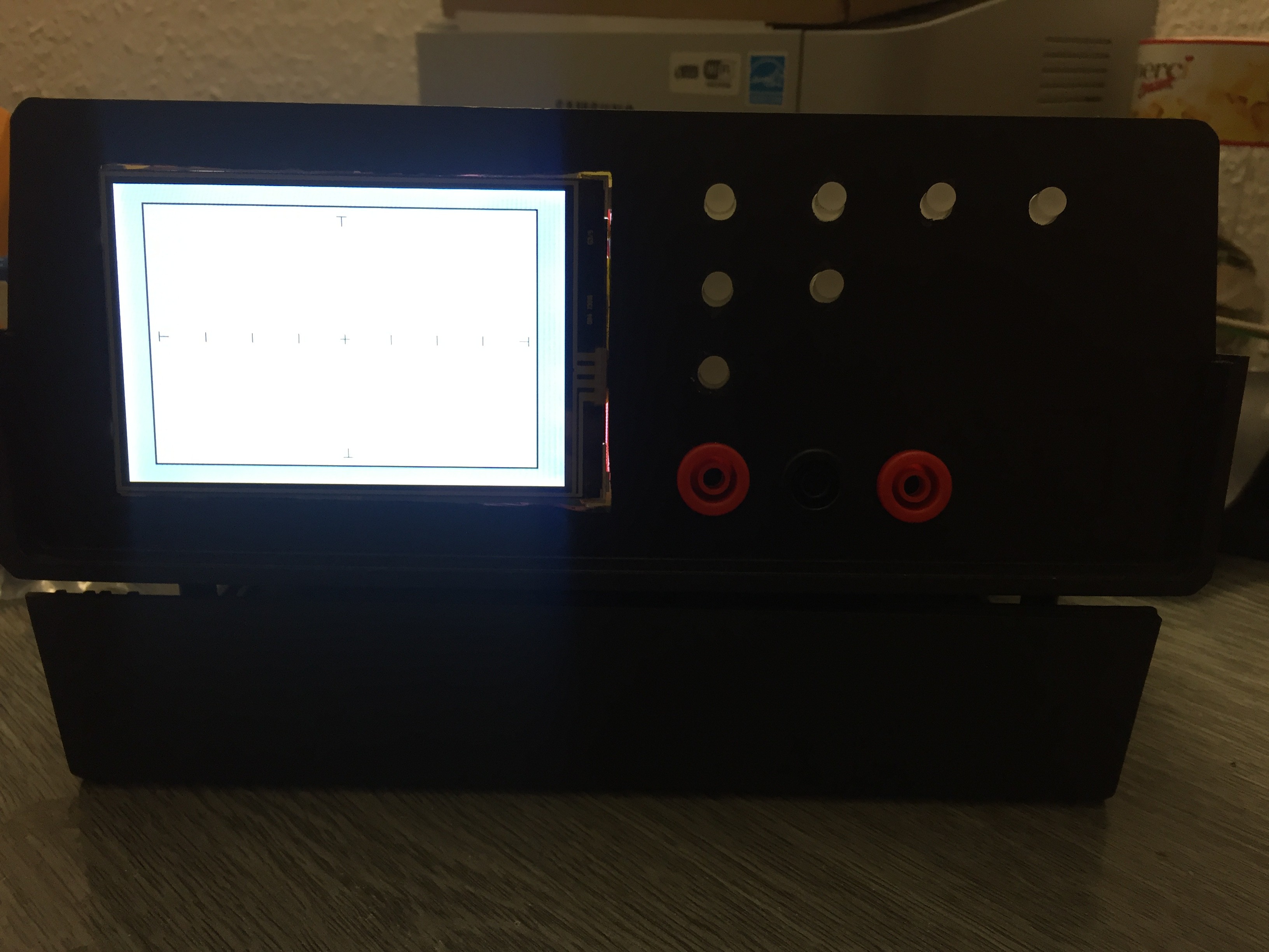
Version 2 front panel demo, test.
01/10/2017 at 22:45 • 0 commentsSo I am done with the case, and the front electronics, the screen, buttons and LEDs all works.
A little demo video, how it gonna look like.
-
A little progress in build Version 2.
01/02/2017 at 19:59 • 1 commentI mentioned in the last log, I had not too much time build the Curve tracer V2, because of the holidays.
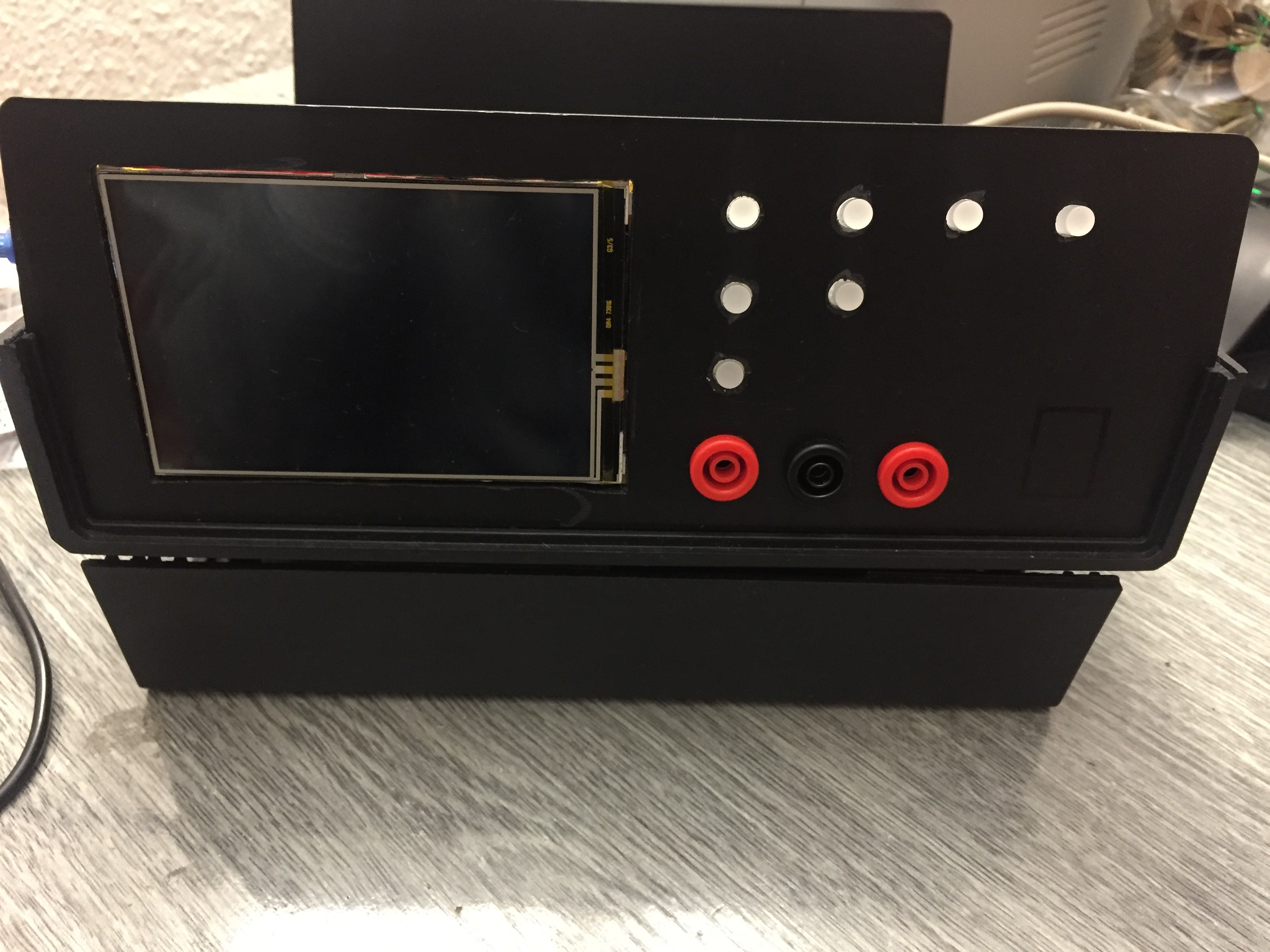
In January I would like to put together the hardware section of the tracker, I did already finish the front of the device, it is looking good I think. After I got the Arduino Due I put ut together with the screen, and started work on the display functions, which is far to be done, but it is something.
The buttons will light up when you selected the mode with them.
I am planning to make a sticker for the front, to hide all mistakes what I made, and also it will looks more professional.
Some picture of the current state:
![]()
![]()
![]()
-
Curve Tracer V2
11/28/2016 at 12:29 • 1 commentI am about to start build the updated version of my curve tracer. I was thinking about a lot, what will I need to improve the functions on the tracer. I was looking the Huntron 3200S spec on the internet, when I specified the functions on mine tracer.
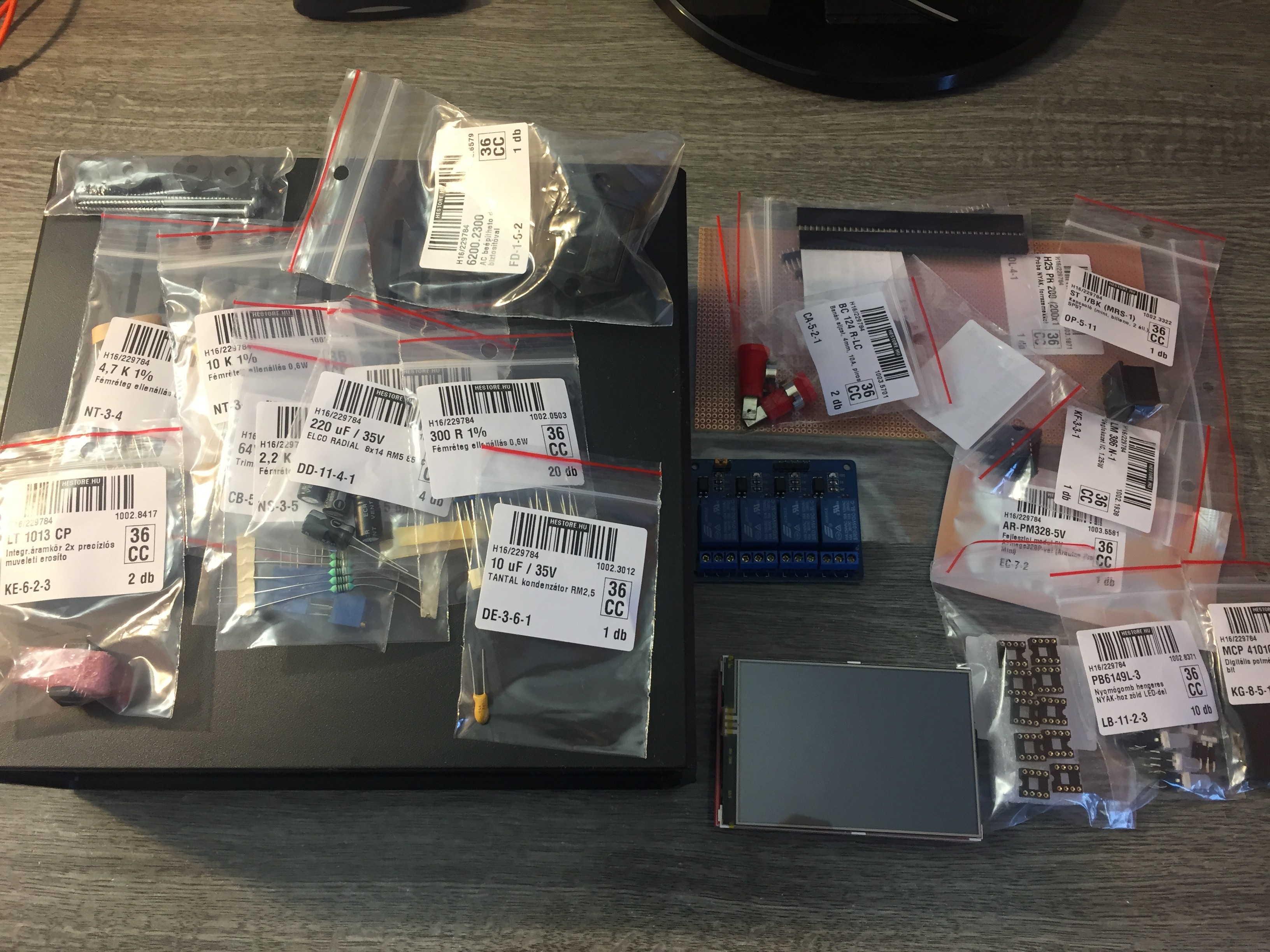
I was sure, if i would like to updrade, I will need more space and a bigger screen, because the last one was a bit small (2.3" LCD). I found a 3.95" LCD touch screen with better resolution (480x320).
The new version will have:
- Two channel input with alternating function, and with that I will able to compare two component at the "same" time.
- Multiple frequency, voltage (sine wave) and input resistance ranges.
- Some buttons with inbuilt LED and a touch display for the easier operation.
- End of the project I would like to make a software for PC and with that I will can log characteristics for save that later repairs.
- If I will have enough money, I would like to make a scanner, wich has around 64 input to measure characteristics on IC-s directly with much better speed.
Only one main part missing, which is an Arduino DUE.
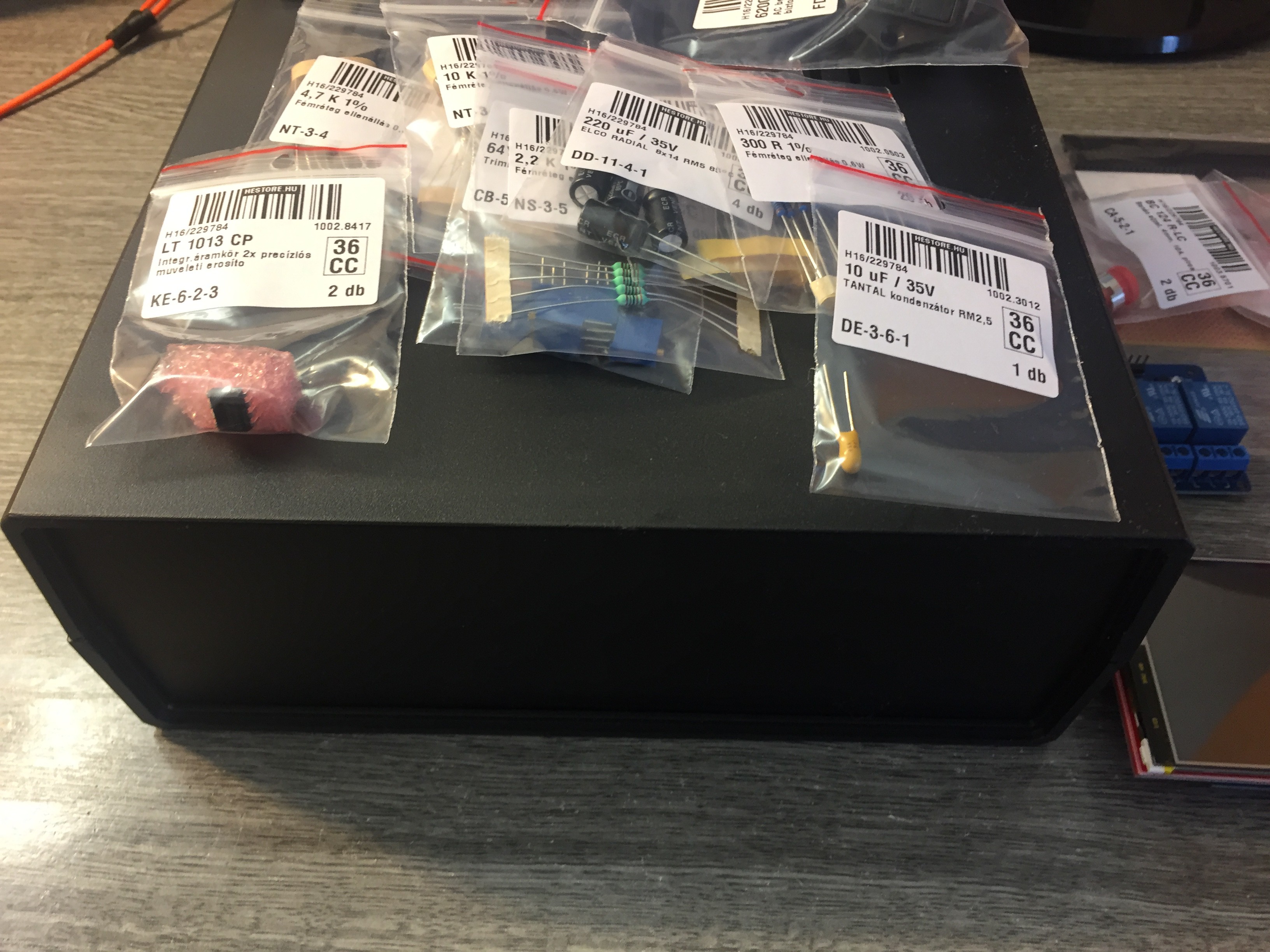
Some photos about parts, what I bought:
![]()
![]()
Microcontroller based curve tracer
Electronic Curve tracer for measure and compare components on circuit boards