Solder Ninja Pen
A 45W Portable USB-Powered Soldering Iron for Makers and Professionals compatible with Weller RT Tips
A 45W Portable USB-Powered Soldering Iron for Makers and Professionals compatible with Weller RT Tips
To make the experience fit your profile, pick a username and tell us what interests you.
We found and based on your interests.
Just as I was confident I had a design that could go into production, the component shortage hit, hard. In particular, the STM32F0 microcontroller at the heart of the product had almost overnight become impossible to source.
A quick chat with a local ST representative made me realize small companies and individuals like me didn't stand a chance against larger companies who were offered the opportunity to bid to secure their supply. I had to find another microcontroller.
I eventually managed to find a roll of some newer STM32G4; only to realize the DC-DC converters were now also unobtainium. After spending weeks browsing through distributor websites, redesigning around components that seemed available, I gave up. It was just too much effort for no tangible result.
But then in summer of 2021, the Raspberry Pi announced the RP2040. With its small footprint, good performance, growing community, and announced stocks, it was the ideal candidate for a final redesign.
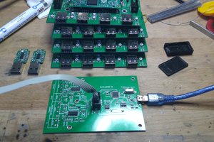
It took some time - and well, the shortages are over - but the dev board works. And the first samples arrived. Next steps? A crowd funding campaign for the first batch. Stay tuned.
I am aware that the following statement might upset some. And yet, open source is something that I truly do believe in. Working on this project, I have come to the interesting realization that there is a difference between design for manufacturing and design for open source that makes not every project the ideal candidate for open source.
Bear me with.
The way I see it, the interest of open source is maximized when the majority of people can actually make use of the published resources, with the least amount of extra steps as possible. It is not good enough to make a product, and say "oh, by the way here are my files", I believe it is important to push things a step further by saying "and this is how you could do it, you, an individual".
And this is what a majority of projects that I see manage to do. But when, in the early stages, I asked myself how I could open source this project, I found myself confronted with a contradiction: the same technical choices that I was making to make this an appealing product where going to prevent people from making an immediate use of what I would share.
In particular, let's take the following three examples:
So, I decided to make the scope of this project twofold:
I fully intend to document both aspects. And I realize this means more work for me compared to just making one device. But I do believe this is the best way to go. Let me know what you think.
Weller RT tips are a beautiful piece of engineering. Some people have gone to the effort of tearing them apart [1] [2]. They embed in a small form factor both a heating element, and a thermocouple, that they expose on just 3 contacts of a 3.5mm jack connector.
A thermocouple makes use of the Seebek effect by which two conductors of different materials joined at one end only will produce a voltage difference at the other end directly proportional to the temperature difference across their length. Thermocouples are arranged by types depending on the pairs of materials used.
That being said, I would like to talk about temperature accuracy. This is probably something on which I spent more time that I thought I would, to be honest. The reason for that is quite simple: there is just not that much information laying around on what type of thermocouple is inside a Weller RT tip.
I found contradicting suggestions that the thermocouple inside could be type-D or the more common type-K. But even if I knew the type of thermocouple, I still had to find a way to ensure the measurements were correct. So I thought for a while, how could I calibrate something that is going to be used at over 300°C?
My initial idea was to use the melting and boiling points of water, putting aside variations in atmospheric pressure, and hoping that the thermocouple response would be linear enough so that a two-points calibration at 0°C and 100°C would still be applicable all the way up to 400°C.
Then I stumbled upon the Hakko FG-100, a calibration device specifically designed for soldering irons, that advertises a +/- 3°C tolerance. I made a few measurements, and determined a linear law to adjust the readings of the Maxim MAX31855 type-K thermocouple to digital converter currently used.
Here is a video showing the final result. Note that the device was powered from 12W supply so that the rising time would be slow enough to see the accuracy over the whole range.
About two years ago, when I first started working on this project, USB Type-C was slowly becoming a thing, and with it along came Power Delivery that was promising power up to 100W. There was a real potential there!
But, USB chargers being nowadays ubiquitous, I decided it didn't make sense both on an environmental point of view, and on a business one to go trough the hassle of stocking and selling USB chargers with the device. Instead people would use their own.
That meant adding support for current non USB Type-C chargers as well. Phone manufacturers have long ago realized that the traditional [1] 5V 0.5A is not enough, and came up with various solutions including the Apple way of using resistors on data lines to allow for up to 5V 2.4A, or the Qualcomm Quick Charge way [2] of using varying voltage levels on the data lines to allow for up to 12V 1.5A.
I wanted that whatever the type of power supply the user plugs into the device, it should always try to negotiate the maximum amount of power. But with that, arose a problem. It meant that the same device could now perform differently based on the amount of power available (for example, heating to 300°C takes around 10 seconds at 18W, but around 15 seconds at 12W). So to ensure a better user experience, I decided that the device should provide visual feedback on the display indicating both the voltage and maximum current negotiated with a potentially smart charger.
I also wanted to maintain the ability to update the product's firmware through USB, which meant that on top of using the data lines for sensing resistors, or changing voltage levels, they should remain available for traditional USB communication.
The current retained solution uses a Diodes Incorporated PI3USB9281 charger detection integrated circuit on the data lines, then a multiplexer that redirects those data lines to either the onboard DACs of the STM32 for HVDCP negotiation or the onboard USB PHY of the STM32. And finally a ON Semiconductor FUSB302 Type-C controller for USB Power Delivery.
Since the initial hardware design, I have stumbled upon multiple other proprietary non-standard charging protocols (OnePlus Dash Charge, Oppo Super Vooc, Huawei SuperCharge, Motorola TurboPower, MediaTek Pump Express) of which little reverse engineering seems to exist. Provided the current hardware design allows for it, I am definitely interested in adding support for those through future firmware updates.
I remember myself at the very beginning of the project trying to sketch on paper what the product should look like. Interestingly enough, this initial shape ended up defining a lot of aspects of the project, and in the two years that I have spent working on it, there hasn't really been a moment where I stopped and questioned whether it was the right choice.
I had already decided that it should be the approximate size of a pencil provided that I could miniaturize everything enough to fit inside. And I defined some additional requirements:
For my prototypes I initially though I could get away with using 3D-printed enclosures made of two parts that would clip on together, but I would eventually always end up braking the fragile 3D-printed details after a few weeks.
So I moved on to metal. With the initial shape being more or less cylindrical, I learnt about threads, and ordered my first CNC-machined prototypes.
I overtime eventually became more aware of what factors impact the pricing of a CNC-machined part, increased the external diameter by a couple millimeters so that it would fit in a perfect cylinder, added a nice notch for the display and buttons and voilà!
As for the inside, I faced a couple of challenges.
Most USB Type-C connectors are conceived for 0.8mm thick circuit boards with a double row of surface mount pins. Those two factors are a problem as 0.8mm is less mechanically resistant, and the second row being under the connector is impossible to inspect visually. Taking into account other factors, the only option left was the very expensive Würth Elektronik 632723300021. At 5 to 6 EUR a piece it was a borderline unreasonable choice, but I have to say that it performs remarkably well.
For aesthetics reasons, I wanted the jack and the USB connectors to be as aligned as possible. But with the jack connector being higher, that meant finding a mid-mount option. Which brought its own set of problems.
Circuit board factories place breakaway tabs in an unpredictable way that is still mysterious to me but I'm sure has to do with ensuring the structural integrity of the whole panel. As a consequence, I've had a few of my early runs fail because the separation process was putting excessive mechanical strain on a clearly too thin part of the board. Even though the amazing guys over at @oshpark have always been kind enough to redo the runs, it was clear that this was becoming a design issue. On an other note, milling trough the whole board for the mid mount connector meant less usable space on the bottom side.
So I thought why not mill only the depth necessary for the mid-mount connector?
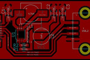
This turned out quite well. The circuit board has better mechanical resistance, and the temperature sensing circuit is now right under the connector for better accuracy.
Create an account to leave a comment. Already have an account? Log In.
Any news or is the project dead? I would be interested in buying
Hey Nicolas,
any update on this project? When can we start buying one :)
One question I do have, is what tips are supported? You say 'Weller RT Tips' but there's 3 kinds, RTP, RTM and RTU, and they are not compatible (the outer ring, RCA style I suppose) has different sizes. If your grip fits the RTU tips, and the smaller ones are 'tight enough' just from the 3.5mm jack, it would fit all the smaller ones as well. Due to the 40Watt limit, I'd argue only RTM and RTP would make sense however.
Weller itself is also not super clear, but yes, there's 3 different holders for the 3 sizes.
I'd buy one when you have it available... be sure to share about that..
Your project is the best! PD, QC, high wattage, upgradeable firmware, beautiful metal case (long lasting, likely travels well). It’s really, really nice.
The TS-80 comes with a Silicon cable, which users say adds a nice touch. This GaN charger also comes with such a cable, except it’s nicer as it’s USB-C on both ends: https://www.indiegogo.com/projects/slimq-world-s-smallest-65w-gan-adapter/x/16789537#/
I'm in for buying at least one of these. Just let us know when and where!
Hi, beautiful soldering iron. I would like to help with open source version!
Become a member to follow this project and never miss any updates

 SUF
SUF

 Ben Holmes
 Casey Banner
HI! Any updates on your crowdfunding campaign?