 igorfonseca83
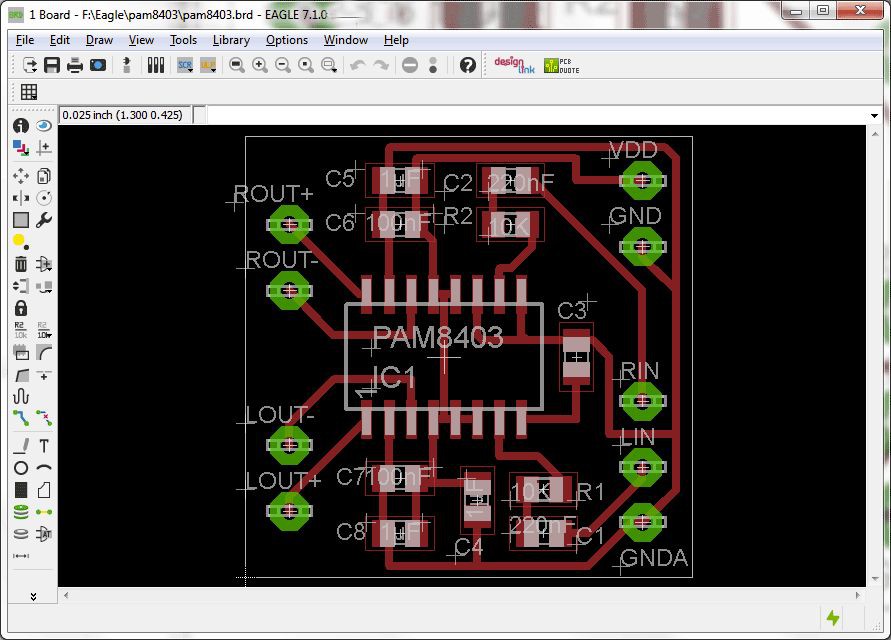
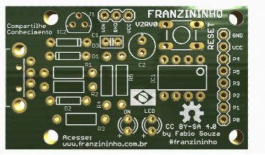
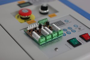
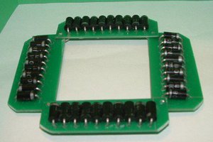
In this tutorial I’ll show you how you I used a low power laser engraver to produce a printed circuit board (PCB). It would be a good alternative if you want to make your first prototype of a circuit board (at least until you order a better version from an online manufacturer!).
You can find the laser cutter I’ve used in the following links:
https://rebrand.ly/laserengraver-BG


 Joseph Lavoie
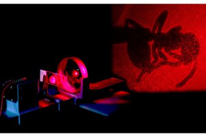
 J
J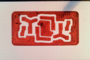
 rolmie