 land-boards.com
Bank Switching is used for RAM Disks and possibly other applications where more memory than the CPU address space is desired.
There are quite a few Z80 memory bank switching schemes out in the wild. Many of them complicate things by trying to replicate a Memory Management unit with multiple banks that can map into multiple locations. For a typical discussion of where this can go see this EEVBLOG thread which goes on for many pages.
Control of bank switching can be done with the PSoC and the Z80. Changing to another bank typically consists of an I/O write from the Z80 to a bank select register. This switches the address of the bank. The PSoC just sees the memory bank control register as a single [up to] 8-bit I/O write which replaces the upper address bits to the SRAM when accesses are in the range of the window.
In the simplest scheme, bank switching involves creating a single window in the Z80 memory space and switching in banks of SRAM into the window.
This is an illustration of the concept for a 16-bit address bus CPU (like the Z80) with a 16KB bank size and a total of 128 KB of SRAM.
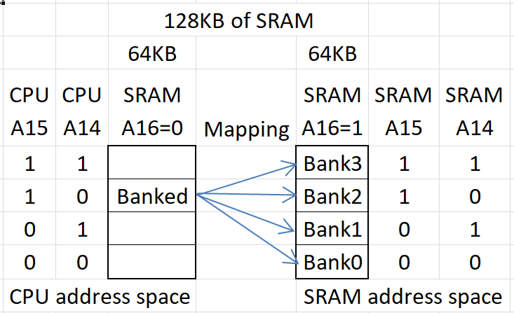
In the example, if the CPU Address is 0x8000-0xBFFF, the bank switch is selected. The upper SRAM address, A16 gets set to 1. Any other CPU address does not get translated but gets directly sent to the SRAM and A16=0. The "Banked" area is actually not filled in the "original" SRAM. SRAM address lines A16..A14 come out of the mapper but only when the CPU address range is the banked space. Outside of the banked range the address lines are unchanged.
The complicating factor here is that the Z80 bank addresses A15 and A14 are replaced by the bits from the bank select register but only when the address is in the banked window. This is set by the Z80 CPU with an I/O write. The relevant factors for banking are:
- Size of the SRAM
- Size of the window
- Address range of the window
The size of the SRAM determines how many banks there will be. The window size determines how many of the upper address bits are altered. The range defines where that mapping happens from the Z80 CPU side and how many bits have to be sent out to the SRAM.
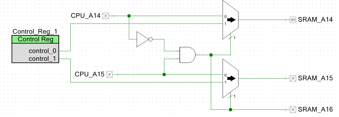
This simple map is implemented as follows:
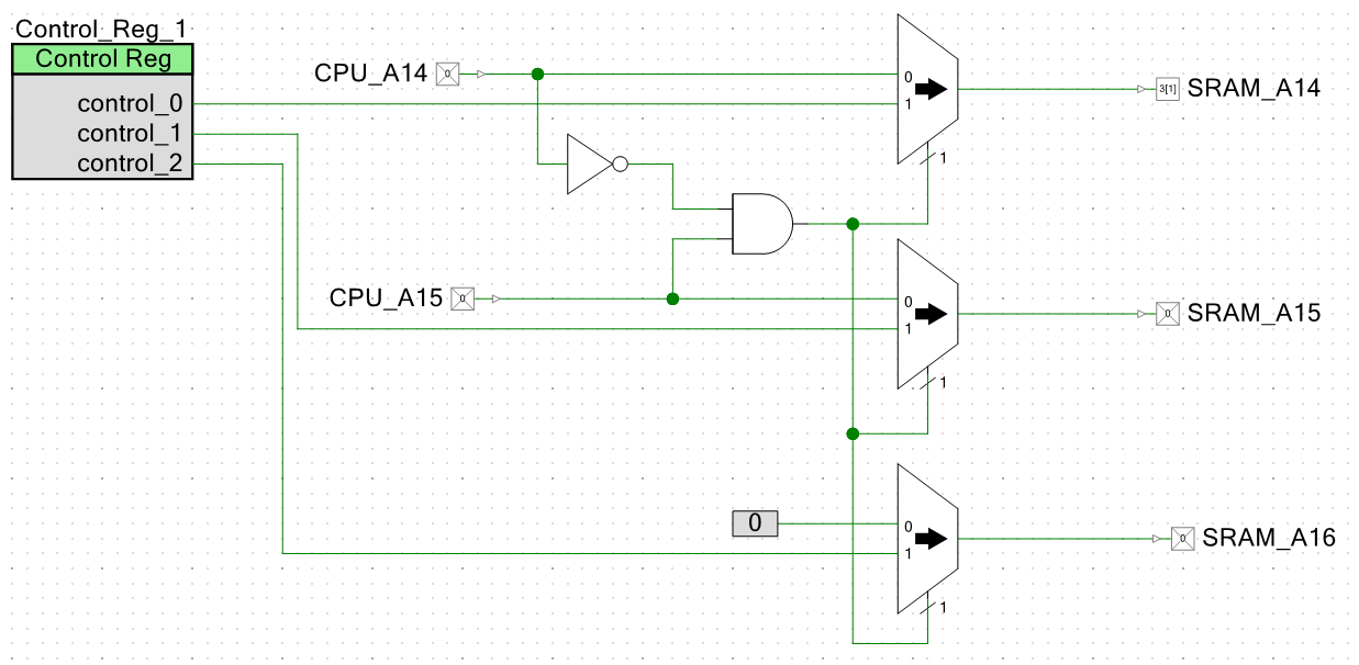
To generalize, SRAM_A16 could be handled with an extra bit from the Control_Register_1 and an additional multiplexer. With this method the 16KB that was "lost" could be recovered. But the mapping register contents have to be more carefully considered to not cause a conflict with the base page. In this instance, it means that the A16 should always be set to 1. Ranges outside of the bank select 0 for SRAM_A16.
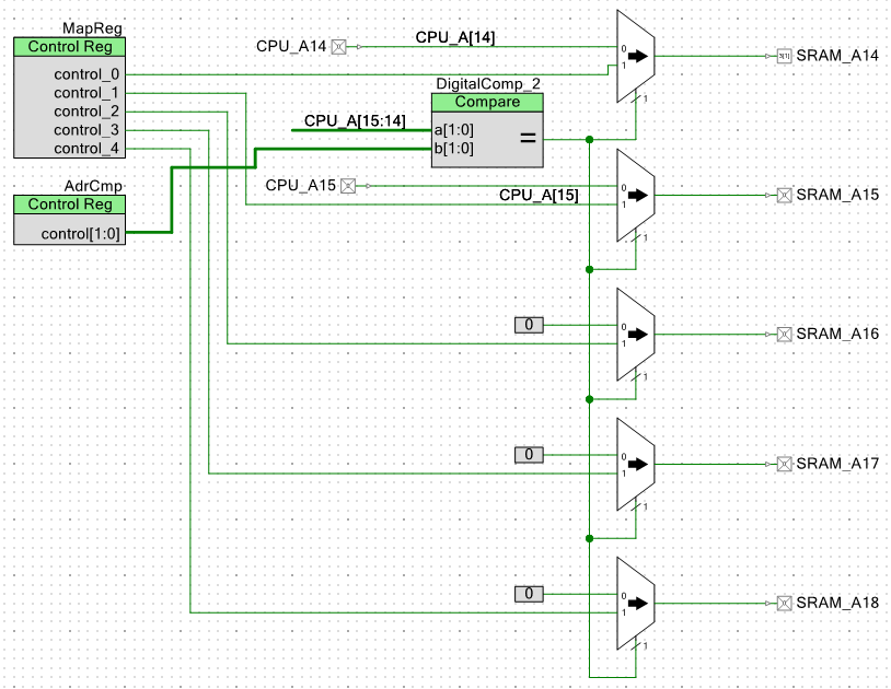
Replacing the SRAM with a larger part, say a 512MB part which has 19 address bits, requires adding two extra SRAM address bits A17..A18. The map register needs 5 bits A14..A18. Address SRAM_A16 also needs to also be treated differently. If the bank size is the same, there's no difference in the A14=0, A15=1 decoding. Also, replacing the NOT-AND gate with a comparator against a value from a register allows any 16KB range in the CPU address space to be replaced by the Banked address.
However, this method introduces a problem, namely banks 0, 1, and 3 now overlap the original unbanked memory space.
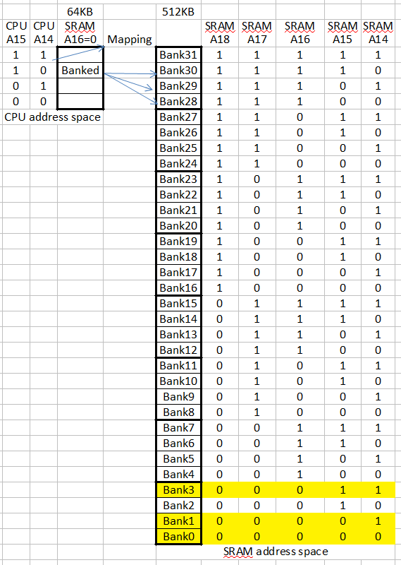
There are two solutions to this problem. Either the Z80 can never ask for overlapping regions, or the PSoC can add 64K to the bank address register to avoid the bottom 64KB. The later is the easier solution. For 512KB of SRAM and 16KB banks, this reduces the number of banks from 32 to 28 but 3 of those banks should not be used anyway. Losing the extra bank (Bank 2 in the illustration) is not much of a hit (1 bank out of 28/32 isn't a big deal). The Z80 could not ask for any banks above 27.
This would be:
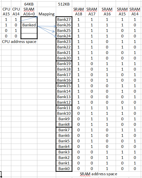
This addition of 4 to the passed bank register value could be done with adder hardware in the mapper or by the PSoC when the bank register value is handled by the PSoC. The later is the easier.
Generalizing the design
As shown, this can be done with fairly straightforward logic but it's a bit harder to generalize the design. Generalizing involves masks and "variable" comparators. At the conceptual level, the mask sets the number of address bits and the comparator looks to see if the Z80 is in the banked range. The two are related. Only bits which are not mapped get compared. Ideally, it would be nice to have both the size and start of the range be programmable. Then, it only needs to be designed once. The PSoC would set this general purpose to make the software needs.
From the perspective of the PSoC, a convenient bank control register size is 8-bits. This would cover SRAMA[18..11]. This means address lines CPUA[10..0] are untranslated. This is a 2K minimum size for the swap block. For 512KB this means there are 256 blocks (the 8-bits of the bank control register). Block sizes need to be a power of 2 and are design/software specific so it would be good for the PSoC to be able to set them under program control depending on the software build.
The CPU address comparator needs to look at A15..A11. This is 5-bits. Any address that does not match these compare bits would get passed through unchanged. But it is desirable to have bank size configurable as well since different builds could use 2K, 4K, 8K, 16K or 32K swap ranges. This necessitates a 5-bit mask register to select the bits that are compared.
These control registers are like this:
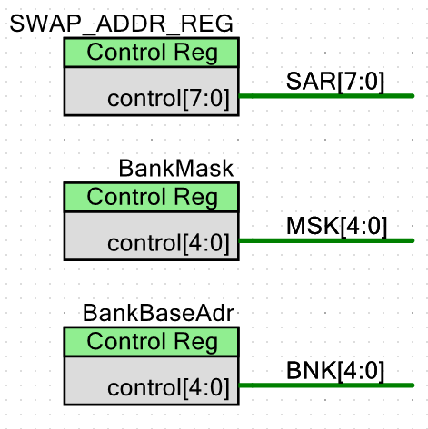
SWAP_ADDR_REG originate from the Z80 CPU plus the offset necessary to avoid the first 64KB. This means that A16=1 is always added to the value. The Z80 ultimately controls whether or not swapping happens by addressing memory in the banked range. The Z80 also determine which SRAM bank gets swapped in by the value it writes to the SWAP_ADDR_REG. The PSoC protects the unbanked space by never allowing writes to the first 64KB of SRAM (adding in the plus 4 into the SWAP_ADDR_REG from earlier).
The BankMask is set by the PSoC. It determines the bank size and should be known for a given software build from the memory map of the software. Bank sizes are 2K, 4K, 8K, 16K and 32K so this could be implemented with a 3-bit register and a thermometer decoder. It is easier to set the values directly. Values are:
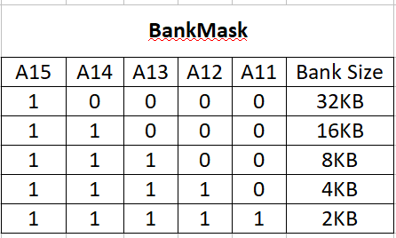
Writing 0x10 to the BankMask selects 32KB banks. Writing 0x1F to the BankMask selects 2KB banks. This is implemented in C as:
#define SRAMBANK32KB 0x10
#define SRAMBANK16KB 0x18
#define SRAMBANK8KB 0x1c
#define SRAMBANK4KB 0x1e
#define SRAMBANK2KB 0x1f
The BankBaseAdr is the address range that is used for comparison with the Z80 CPU address bits. It is masked by the BankMask which determines the number of bits which should be used. It is a constant value and is also known for a given builds.
With this information we can build the bank address range comparator.
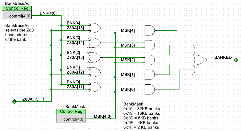
The XOR does a comparison of the BankBaseAdr bit with the Z80 Address. If the bit is different the output of the XOR is 1. The BankMask bits determine whether or not the bit "matters" in the comparison. The output is the BANKED signal which indicates that the selection is banked.
The Address mapping, then, is performed with a set of 2:1 multiplexers. The BANKED bit controls the multiplexer selection.
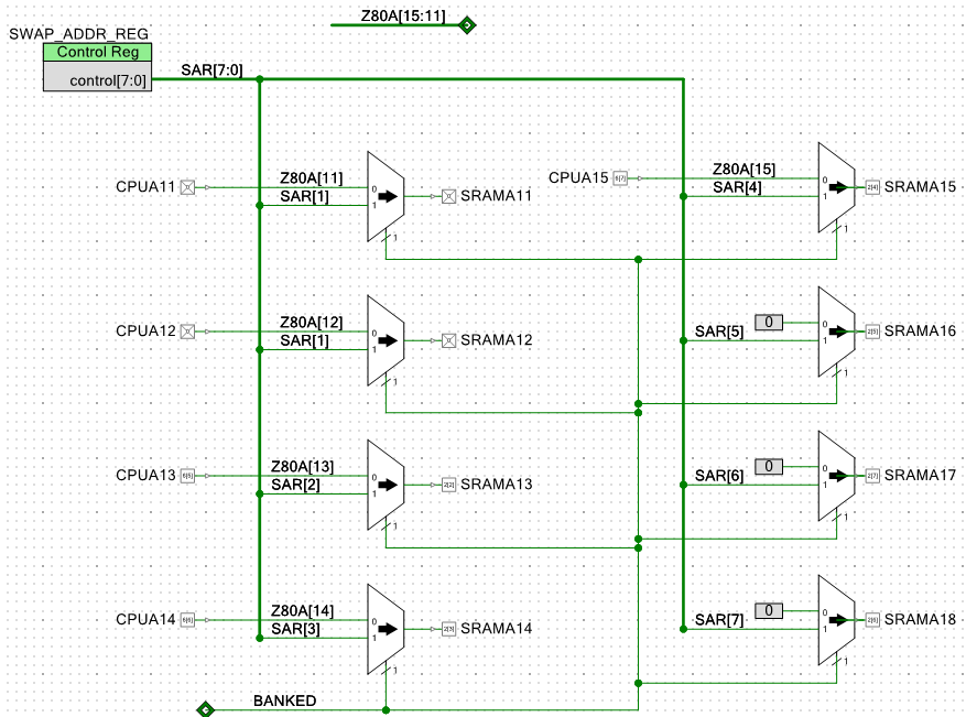
So the only caveat here is that the bank select register has 4 added to it before it is put into the SWAP_ADR_REG. This would not be necessary if the Z80 software is aware of the banking scheme.
Discussions
Become a Hackaday.io Member
Create an account to leave a comment. Already have an account? Log In.
Interesting ! So just to be sure that I understand properly, let's take the first implementation for 128k and the 2 bit control register :
1) The Z80 sets the "control register" with an "I/O write". By that, you mean that the Z80 puts IORQ and WR active, with the lower half of the address bus pointing to a device that latches 2 bits from the data bus, pre-selecting the bank for later.
2) When the Z80 want's to read or write with MREQ active AND an address within the banked window THEN you replace A14 and A15 with the 2 bits latched earlier and put A16 to high. Effectively choosing one of the four 32k banks within the upper half of the 128k RAM.
Is my understanding correct ?
Thanks
Are you sure? yes | no