 land-boards.com
The RESET* line into the MCP23017 I2C Expansion IC is wired to the CPU reset so it can't be programmed if the Z80 isn't running. Moved the PIO initialization code to only be executed when the RUN button is pressed (since it takes the Z80 out of reset(.
Could take the Z80 out of reset by downloading loop forever code. At present, I am just running the BASIC_CP/M build since it lets me INP and OUT to I/O space.
After initializing the MCP23017 parts, the I2CINT* line is high. Pressing the RUN button on the Front Panel sets the I2CINT* line low.
PRINT INP(24) - Clears the interrupt left over from when the run button was pressed. The interrupt is still present since the key press is longer than the input MCP23017 processing time.
The MCP23017 is running as a PIO emulator. The Z80 IO addresses are:
        #define PIOA_D              0x20    // decimal 32
        #define PIOA_C              0x22    // decimal 34
        #define PIOB_D              0x21    // decimal 33
        #define PIOB_C              0x23    // decimal 35
The PIO User manual shows the command interface. but it is somewhat modified since it is emulated by the PSoC. The PSoC has a state machine design which implements the setting of the port mode
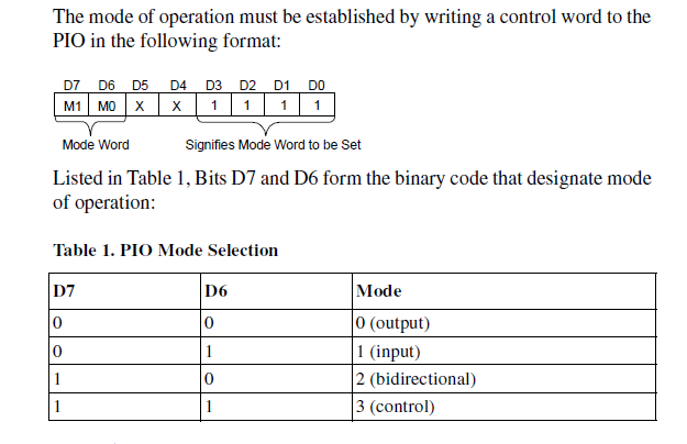
OUT 34,79 - sets the PORT_A mode selection to Input. 79 dec is 0x4F.
OUT 35,79 does the same for PORT_B.
It looks like the input polarity register in the MCP23017 is pre-applied to the interrupt comparison default value.
The same applies to the JOYPAD. It pulls lines low so the input polarity is set to invert. The comparison value then, has to be set to 0.
After some tweeking the I2CINT* is only set by the last keypress on the front panel and can be cleared by reading INP(24). The Front Panel code could hang around until no keys are pressed and then clear the Interrupt Capture for the Front Panel.
But, this won't work as well for the keypad.
Interrupt Servicing
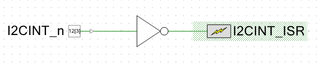
Added interrupt hardware to the schematic. Again pretty simple to add the hardware.

PSOC Creator made the interrupt handler file I2CINT_ISR.c which has the API templates and routines.
- I2CINT_ISR_Start( ) - starts up the ARM code for the Interrupt
To start with the Interrupt Handler just clears the interrupt.
CY_ISR(I2CINT_ISR_Interrupt)
{
    #ifdef I2CINT_ISR_INTERRUPT_INTERRUPT_CALLBACK
        I2CINT_ISR_Interrupt_InterruptCallback();
    #endif /* I2CINT_ISR_INTERRUPT_INTERRUPT_CALLBACK */

    /*  Place your Interrupt code here. */
    /* `#START I2CINT_ISR_Interrupt` */
    #ifdef USING_FRONT_PANEL
          readRegister_MCP23017(0x24,MCP23017_INTCAPA_REGADR);                            // Clears interrupt
          readRegister_MCP23017(0x25,MCP23017_INTCAPA_REGADR);                            // Clears interrupt
          readRegister_MCP23017(0x26,MCP23017_INTCAPA_REGADR);                            // Clears interrupt
          readRegister_MCP23017(0x27,MCP23017_INTCAPA_REGADR);                            // Clears interrupt
        I2C_Start();
    #endif
    #ifdef USING_EXP_MCCP23017
          readRegister_MCP23017(0x20,MCP23017_INTCAPA_REGADR);                            // Clears interrupt
          readRegister_MCP23017(0x20,MCP23017_INTCAPB_REGADR);                            // Clears interrupt
    #endif
    /* `#END` */
}
The code is pretty dumb. It doesn't do anything other than the reads of the interrupt capture register which clears the interrupt. But it works and the interrupt line is no longer low. So, I no longer have to read INP(24) to clear the interrupt.
Hardware Changes in Rev 3 Card
Removing the RESET* line from the MCP23017 and pulling up the pin to Vcc. This will let the PSoC work with the MCP23017. This means an etch cut and add of a pull-up resistor on the Rev 1 board.
This change is actually mandatory since when the MCP23017 is held in reset it wants to drive the interrupt line and it bucks the MCP23017 chips on the Front Panel which are driving the interrupt line to the opposite state - not good.
PSoC Interrupt Change
Working details - the PSoC allows 3 types of interrupts. Of the three, RISING_EDGE seems like the right one since it will only activate on the edge. Level could be better but I can't see where the level (high or low) gets set. It's probably for High, though.
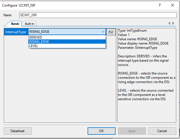
Either way, this means I needed to change the schematic for the interrupt pin and interrupt function.
This lets the PSoC code detect the interrupt activation. The problem I found was this put me right back in the mode where I had to INP(24) to clear the interrupt line. And it isn't causing an interrupt anymore so that's better.
I did notice the interrupt going twice earlier. May be one for each edge of the input or could be a bouncy switch?
Switching to LEVEL fixed the problem of the interrupt getting missed. That's probably the right solution since it will keep calling the interrupt routine until it clears the interrupt completely.
The interrupt routine is getting called many times matching to the switch press duration. As soon as the routine exits the key is still pressed and the MCP23017 immediately goes at it again.
The card got stuck and here's why:
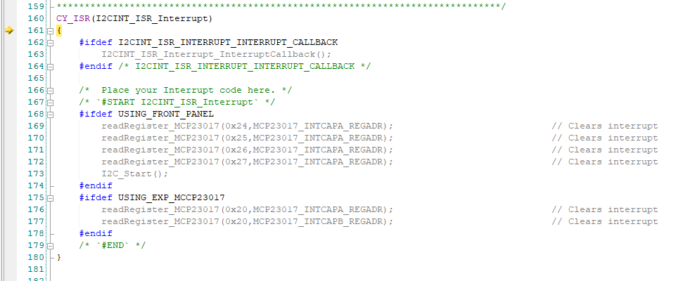
The grey sections show that the code is not included. When PSOC Creator built the code it remove the .h files that define these functions and the compiler, being smart took them out. I need to move the interrupt handler out of this file to prevent this in the future. PSOC Creator preserved the code in the area that they mark with comments and that is good so it wasn't lost but rewriting thee top of the auto-generated file removed the .h file that has the #defines for the function inclusion.
I am now back at the spot where the interrupt is being cleared which is good. Pressing a button on the Front Panel also causes and interrupt which gets eventually cleared. The Z80 code is being run (CP/M or MBASIC). There's once again no need to INP(24) to clear the interrupt.
That is all very good progress, but the JOYPAD still isn't working. Pressing buttons on the Front Panel works fine now so I could even use one of the buttons to reset the Z80 - a good goal in and of itself.
There must be some difference in the init code for the Front panel vs the Expansion MCP23017 parts.
The Front Panel init code is:
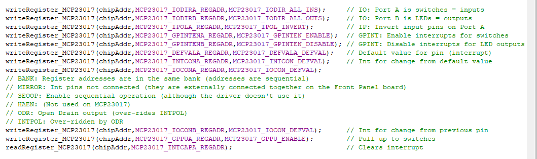
That looks the same as the Expansion MCP initialization code. I wonder if the PIO commands need to be done from the Z80? Tried it and it didn't help.
I haven't checked this JOYPAD card out. Is it really working? Wow, rookie mistake! The connector on the cable is plugged in backwards at the Z80_PSOC end. Sometimes it pays to have a good sense of humor and just laugh at yourself.
Now pressing buttons on the JOYPAD does the same thing as pressing buttons on the Front Panel. They cause an interrupt to the PSoC just like they should.
Good spot to end this log. I'd like to have the pressing of the keypad cause a key value to be sent to the Z80 - just like a keyboard press. Right now, I think they would produce a lot of keys.
Discussions
Become a Hackaday.io Member
Create an account to leave a comment. Already have an account? Log In.