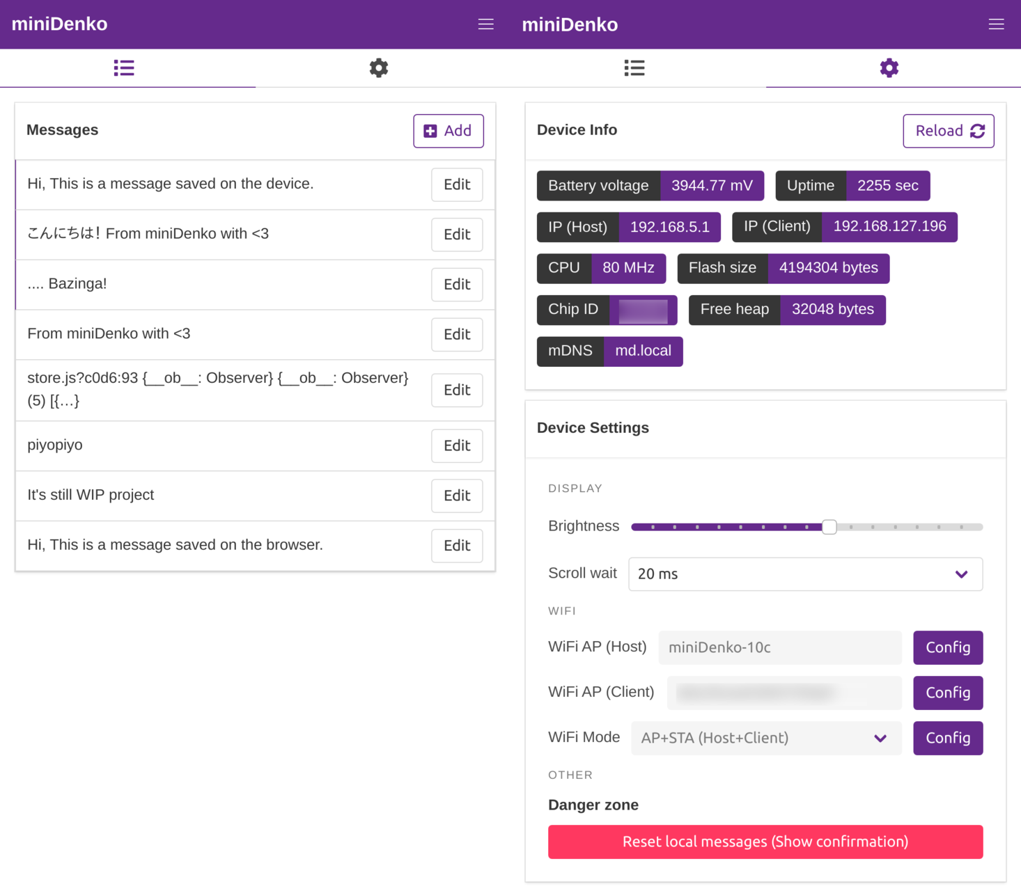
Close
0%
0%

miniDenko

Yet another ESP-powered portable messaging device.

Similar projects worth following
miniDenko is an ESP-powered portable messaging device.
(Denko = 電光 is from "electronic message board" in Japanese) .
You can save & show any text stream on it via browsers.
Also it's fully controllable with a simple JSON API.

## Features

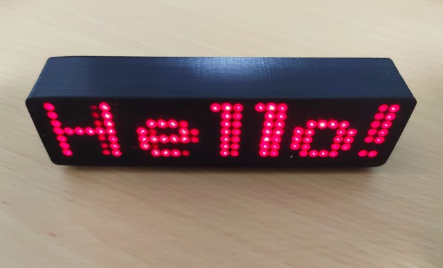
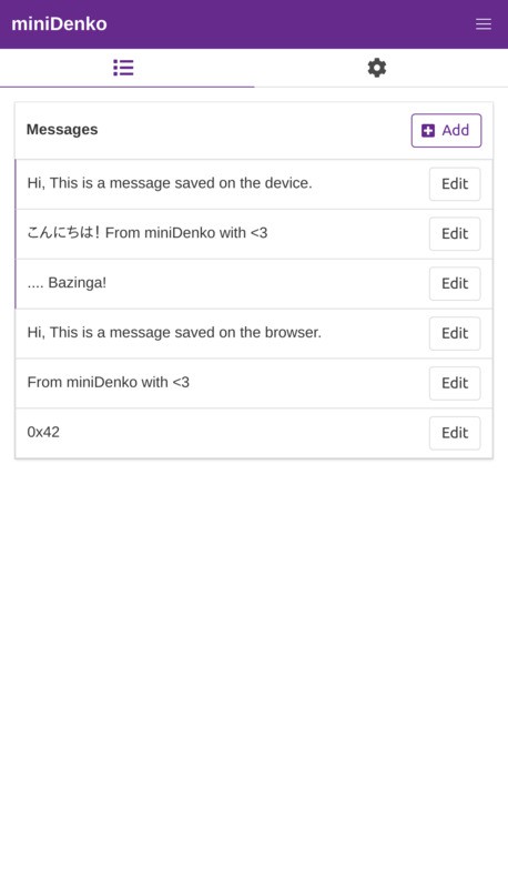
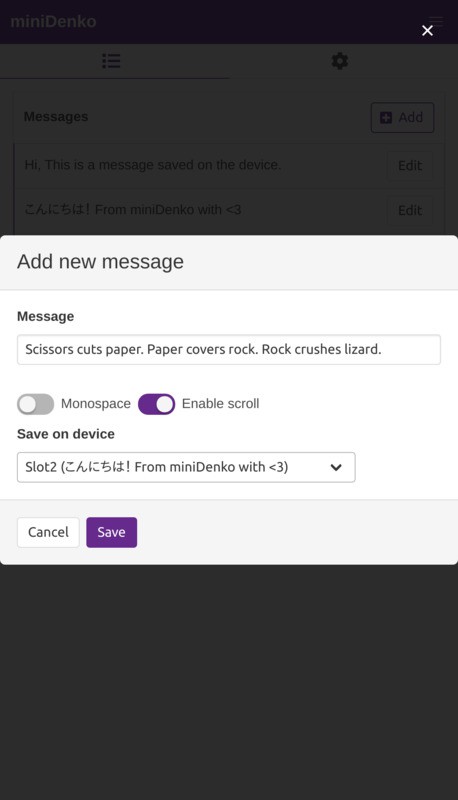
  • Edit & save your message and show it up instantly.(Sub-second booting) 
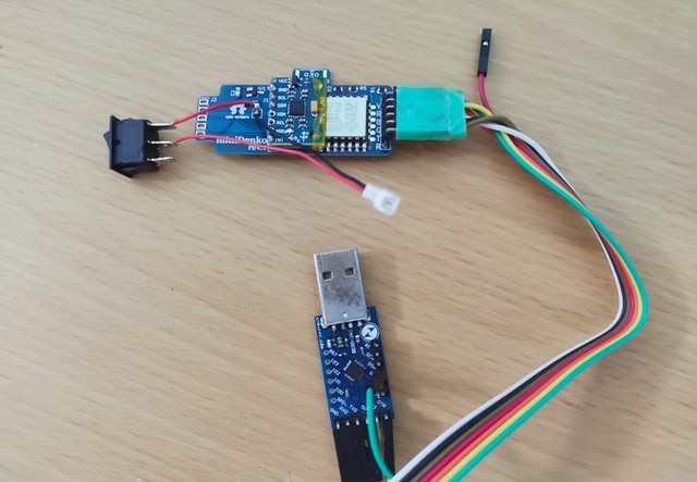
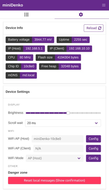
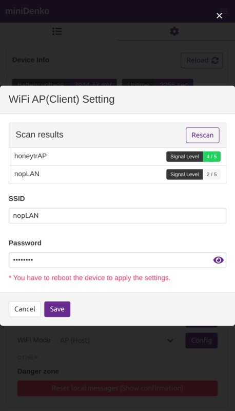
  • Easily connectable with Phones, Laptops, etc. via WiFi. 
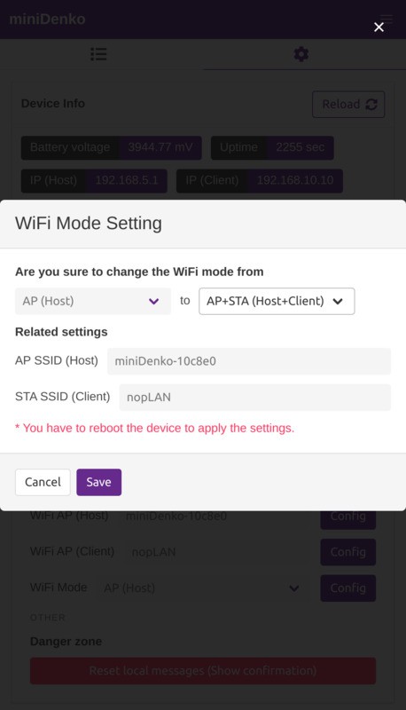
    • Supports `STA`, `AP`, `AP_STA` modes to collaborate with the devices.
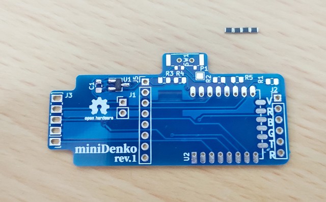
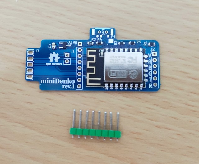
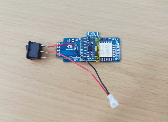
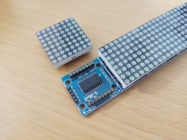
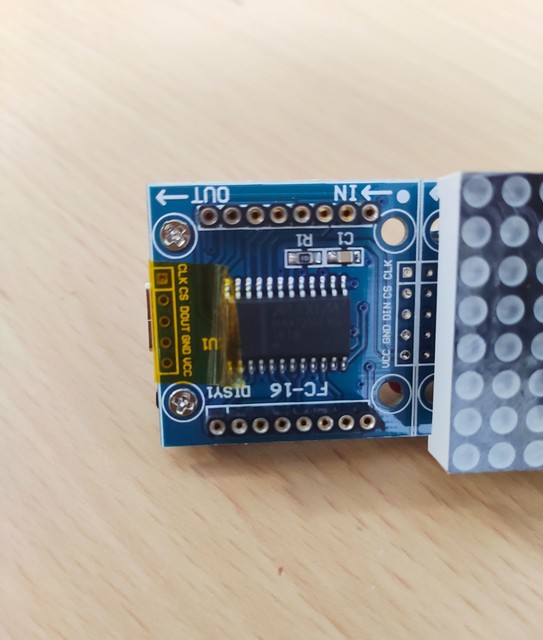
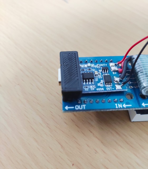
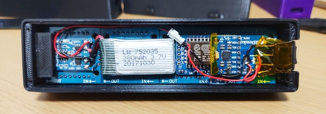
  • Made from easily-obtainable parts. (See [#BOM](#BOM))
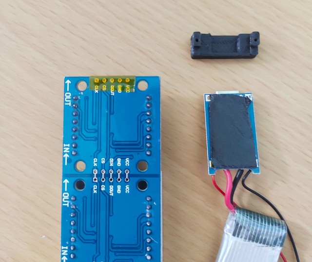
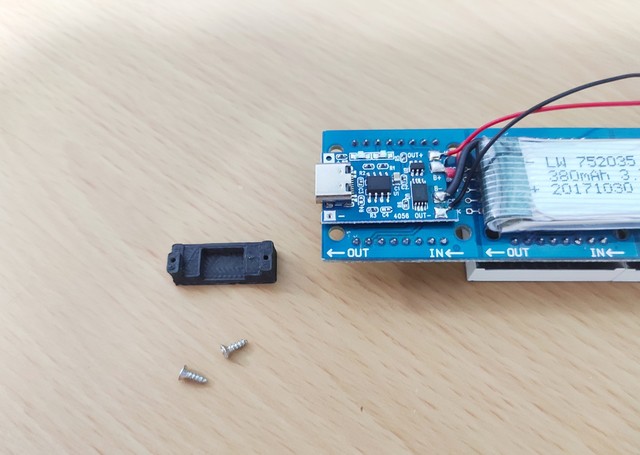
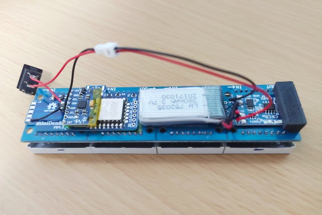
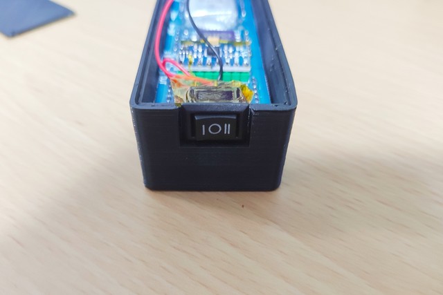
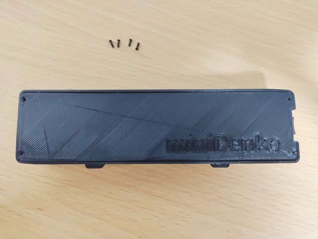
  • Its [portable and slim shape](./openscad/minidenko-case-body-opaque.stl) fits in your (large) pocket.
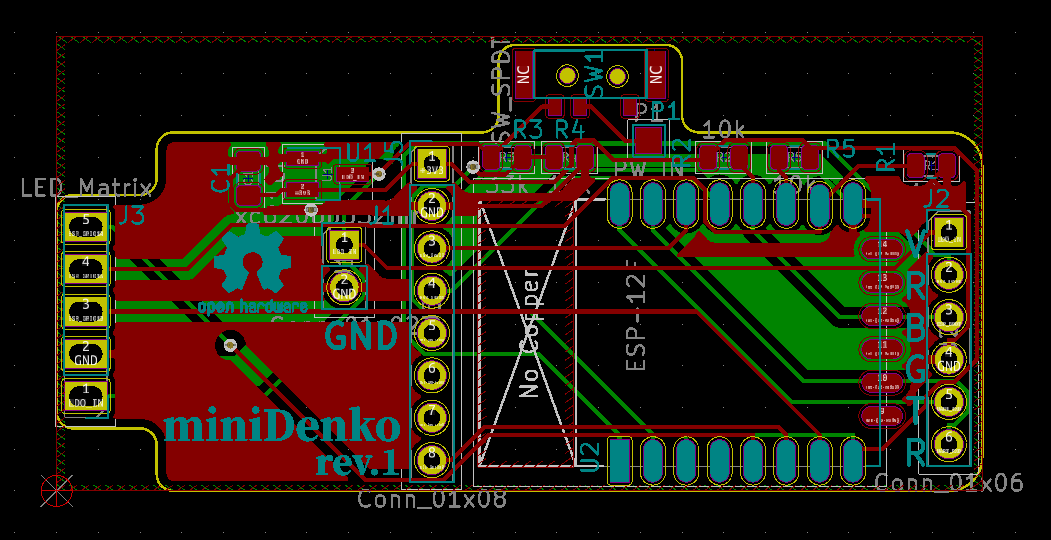
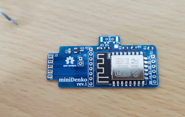
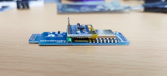
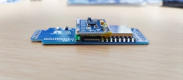
  • LED Matrix + esp8266 + MPU6050 + Modern Web framework(Vue.js + Buefy) = A hackable LED messaging platform
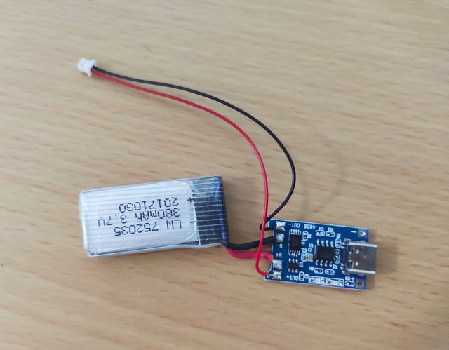
  • And as a latest gadget should be, equipped with the **Type-C** charging port.

Zip Archive - 78.14 kB - 10/13/2019 at 05:54

Download

stl-binary - 498.70 kB - 09/25/2019 at 15:25

Download

minidenko-case-body-opaque.stl

For opaque filaments

stl-binary - 282.49 kB - 09/25/2019 at 15:25

Download

minidenko-case-body-transparent.stl

For semi-transparent filaments

stl-binary - 279.19 kB - 09/25/2019 at 15:25

Download

stl-binary - 58.24 kB - 09/25/2019 at 15:25

Download

  • 1 × ESP-12F (ESP8266 module)
  • 1 × 8x32 LED Matrix board (MAX7219)
  • 1 × 3.3V LDO xc6206p332mr (SOT-23)
  • 2 × M2 x 6mm self tapping screw
  • 1 × SPDT rocker switch (10x15 mm)

View all 12 components

View project log

  • 1
    (Order PCB)

    ZIp the gerber folder and order PCB from a online PCB fabrication services (e.g. Elecrow, FusionPCB, etc.)

    • No. of layers: 2
    • PCB DImentions: 28x56mm
    • PCB Thickness: 1.0mm
    • PCB Color: Choose as you like

    Shipping fees may vary depends on where you live, of course. However the cost for PCB itself might not exceed 10 USD for 10 PCBs.

  • 2
    Switch on your soldering iron, it's time to...
    All the parts (except screws, some SMD parts)

    All the parts (except screws, some SMD parts, wires)

    • R3: 33k
    • R1, R2, R4, R5: 10k
    • U1: xc6206p332mr
    • C1: 1uF
    • U2: ESP-12F
    • Push down the plastic part on the 2.54mm 1 x 8 pin header to not stick out from the back side of the PCB.
    • J5: GY-521
    • Pay extra attention to the terminals of the LiPo battery when you cut it. Don't short circuit it!
    • Let's burn the firmware to ESP. 
    • J2 Pin definitiion
      • V: 5V(LDO_IN)
      • R: ESP_RESET: RST pin:  
      • B: ESP_BOOT: GPIO0 pin: 
      • G: GND
      • T: ESP_TXD: TX pin: 
      • R: ESP_RXD: RX pin: 
    • Detach the LED Matrix from the board, and cut the L-type pin header by a nipper.
    • FIx the battery and the LiPo charing board to the LED matrix by using  a piece of double sided tape.
    • Put the LED matrix back to the board.
    • Power on and let's see how it works!
  • 3
    Connect your device with miniDenko

    WIP

    • Scan and connect to the AP named "miniDenko-xxxxx"(here xxxxx is a unique chip ID)
    • Open http://192.168.1.5/ in a browser (Chrome recommended)
    • Here you can edit & submit new messages ( Try to tap the "Add" button)

    • miniDenko internally has 3 "slots" for preserving messages. You can "tap" the device to switch the messages.

    # To connect your miniDenko to another AP

    • Tap ⚙️ and go to the setting tab
    • Tap "Config" button next to "WiFi AP (Client)"
    • Input your AP's credentials and tap "Save"
    • Then you have to change the WiFI mode to "AP+STA", 
    • Tap "Config" button next to "WiFi Mode"
    • Reboot your miniDenko to apply the settings.
      • You can see miniDenko's IP at the "IP(Client)" badge.

View all 3 instructions

Enjoy this project?

Share

Discussions

Similar Projects

Does this project spark your interest?

Become a member to follow this project and never miss any updates