-
SIMPL Revisited
01/21/2020 at 20:20 • 2 commentsBack in late October, just as I was starting to hand-code some assembly routines for Suite-16, I considered porting my bytecode interpreter SIMPL across from MSP430 assembly language to that of the Suite-16.
Unfortunately at that time, the instruction set was very much in a state of flux and still evolving, and hand assembly was somewhat time-consuming. Revisiting this task now that we have an assembler and a hexloader in our toolchain armoury makes the job so much easier, and I have transcribed the SIMPL framework in a long afternoon sprint of about 6 hours coding. As well as the code, it is highly commented, thus documenting the workings of the SIMPL interpreter as I went along.
What is SIMPL?
At it's most basic level it is an interpreter consisting of a switch statement contained in a loop.
After all - that is how most simple processors and virtual machines are simulated. To make the job easier in assembly language - the switch statement is replaced with a jump table, with one 16-bit entry for each of the 96 printable ascii characters. In essence, when a command character is read from the input buffer, it is used to index into the jump table and pick up a 16-bit address for the code-block associated with that command.
SIMPL is stack based, so numbers are put onto the stack and operated on from there.
It is a tiny-Forth-like utility language without the complexity of the dictionary and text string matching that is needed in a full-blown Forth.
So the commands include familiar mathematical and logical symbols such as + - * and /, which obviously relate to arithmetical operations.
Then there are the stack operations - familiar to those using Forth, such as DUP, DROP, SWAP and OVER. In addition there are commands associated with decimal and hexadecimal number entry and also output routines to a serial terminal for decimal, hexadecimal and hex-dump formats.
The user has 26 commands available - that can be user defined and customised. These are represented by the uppercase characters A to Z. The language is extensible just by assigning a user command to a snippet of instructions.
SIMPL provides a minimal framework, consisting of serial input and output, number conversion, text interpreter, command allocator plus a range of arithmetical, logical, stack and memory operations. From this collection of built in routines, elementary applications can be assembled.
For example, if you were developing an application for a hex monitor, to view the contents of memory on screen in hex, edit it and save it back to memory you would assign characters for all the commands that you would need.
A set the Address
C Clear memory
D Dump memory
E Execute the routine
Alternatively if you were developing an application to control a CNC machine, plotter, 3D printer, robot etc you would probably use the X, Y, and Z characters that define the co-ordinates you wish the machine head to move. The SIMPL interpreter can read these in one line at a time from an ascii text file to control the motion of the machine, or to draw graphics on a screen. This is similar to the manner in which G-Code is used to control CNC machine tools, or Gerber files are used to control a photo plotter for pcb manufacturing. These simple control tasks evolved in the 1960s, when processing power was very limited, so the application itself had to be kept non-complicated.
SIMPL is very compact.
The minimal interpreter framework with all the input and output utility routines is under 256 program words. The Jump table is a further 96 program words. To this you must add the action routines associated with all of the potential 96 commands - but these are often very small - each only a few instructions long.SIMPL is easy to tailor to your own application, as rudimentary or complex as you wish. If you want commands for floating point math routines then these can be added. Generally I use it for exercising new hardware - or in this case thrashing out any discrepencies in the Suite-16 instruction set.
I have placed the SIMPL framework in my github repository here: - it is as yet untried and probably buggy - but gives an idea what can be done with a couple of hundred words of assembly language.
-
A New Year - and 2020 Vision.
01/13/2020 at 16:20 • 2 commentsIn mid-November, I traveled out to Northern California, to attend Forth Day at Stanford University - and to meet one of my Computing Heroes, Charles H. Moore - the inventor of Forth. Returning in late November, I got stuck in a bit of a rut, plus a lot of other things were putting pressure on my free time - which meant that the Suite-16 project was put on the back-burner with no further progress. My project-colleague, Frank, is currently touring Australia and Tasmania for the duration of January, and so that gives me a two-week window of opportunity to take stock of the project so far and plan out the goals for 2020.
It was always my intention that Suite-16 would exist as a C-simulator, a computer implemented in standard TTL and as a verilog implementation to run on an FPGA as a soft-cpu. In discussions with Frank, we have decided that now we have a working simulator, the next step is to convert this into a soft-cpu developed and running on opensource FPGA hardware. When this task is done, I will have had a lot more experience writing in verilog, and Frank and I, will have stable target hardware platforms with which we can do real system development. The TTL processor will follow on later, as it will be a lot of hard work, but at least the architecture will have been thoroughly explored and documented by that time.
The FPGA family I have chosen to use is the Lattice ICE 40 series. I first encountered these in early 2015 when Clifford Wolf announced his "Project IceStorm" reverse engineered, opensource FPGA toolchain - allowing the Lattice parts to be programmed using a manageable, open source toolchain. One of the first soft-cpus to benefit from this announcement was James Bowman's J1 Forth CPU. Video here: James had previously used Xilinx parts for earlier implementations of his J1, but by May 2015 had proven that it would easily fit onto a ICE 40 HX1K - which is a 1K lUT FPGA used on the $25 Lattice IceStick development board. James and I have collaborated on a couple of projects, having first met at the Open Hardware Summit in New York in September 2011.
In May 2016 a friend, Alan Wood, and I decided to develop an opensource FPGA dev-board based on the Lattice ICE40 HX4K. The result was the myStorm BlackIce, which is now into it's fifth generation. Hardware development took about 14 weeks from idea to the first 250 boards arriving from the manufacturers in Shenzhen, China. We debuted at the 2016 OSHCamp (Open Source Hardware Camp) held annually in Hebden Bridge, West Yorkshire, UK.
In November 2016, I met up with James again at Forth Day in Palo Alto, where he had implemented his J1 cpu on one of our BlackIce boards, and was serving his presentation as a series of jpgs from it. The BlackIce hardware had been fully exercised and proven robust and reliable - and makes an ideal platform for soft cpus or SoCs.
The 2nd generation BlackIce II board has a Lattice ICE 40 HX4K FPGA and 256K words of 16-bit, 10nS SRAM. Programming (configuration) is done over a USB connection, using an STM32L433 ARM Cortex M4 to act as the programming interface. We could have just used a FTDI FT2232H as a USB to SPI converter (like everyone else does) - but frankly at $3.50 the FTDI device is too expensive and the STM32 offers so much more flexibility for less money. Once the FPGA is programmed, the STM32 can be used to provide slave peripherals for the FPGA (such as ADC, DAC, UART, I2C, SPI etc). Later generation of myStorm boards have all adopted this ARM/FPGA symbiosis.
Implementing a soft-cpu in verilog
verilog, like vhdl is a popular hardware description language or HDL. verilog has its roots in C, whilst vhdl arose out of the US department of defense and is structured like Ada. Both are equally used, but verilog has my vote, because I know nothing about vhdl syntax.
When James Bowman transcribed his J1 cpu to verilog, he implemented it as a very neat switch-case (casez) statement in fewer than 110 lines of verilog in his J1 Github repository.
Using James's code as a useful tutorial example, it's fairly easy to see how an instruction set implemented as a switch-case statement in C, translates cleanly to verilog. His code is well commented and easily readable, nobody likes obfuscated code (apart from obfuscated code masochists).
This code is just the cpu, and the interface to memory implemented in internal BRAM. In a practical working system we will also require a module of code to define a serial communications UART, an external SRAM interface and if we are feeling adventurous, a VGA colour graphics interface and external frame buffer. For a complete system a PS/2 keyboard interface would also be useful - and this can be added as a PMOD - external hardware module.
-
PRINTHEX
11/05/2019 at 22:50 • 0 commentsPRINTHEX is probably the last of the utility routines that I needed to write in order to get a simple hex loader to run.
It accepts a 16-bit integer value from the accumulator R0 and prints it out as a 4-digit hexadecimal number. Leading zeros are not suppressed.
It is based on the decimal number print routine PRINTNUM, but with the added complication that the hex character sequence is not contiguous in the ascii table.
This is likely to be the last of the hand-assembled routines, because my motivation is from now on to use the TASM32 assembler - kindly customised for the Suite-16 instruction set by Frank Eggink.
Having a working hex loader with hex dump and simple monitor commands will be the next goal!
Here's just the PRINTHEX assembly code - it fits nicely into 48 words of memory:
// 0x0070 ---------------------------PRINTHEX----------------------------------------- // Prints out contents of R0 as a 4 digit hexadecimal number to the terminal // Leading zeroes are not suppressed // R1 = Heximation Value // R2 = digit // R3 = 0x30 // R4 = temporary storage for accumulator (Heximated value) // R6 = temporary store for output character 0x1200, // SET R2, 0x0000 0x0000, 0x1300, // SET R3, 0x0030 0x0030, 0x1100, // R1 = 4096 0x1000, 0x088C, // CALL Heximate 0x1100, // R1 = 256 0x0100, 0x088C, // CALL Heximate 0x1100, // R1 = 16 0x0010, 0x088C, // CALL Heximate 0x0A30, // ADI 0x30 to make a number 0x3600, // Store in R6 0x0B3A, // SBI 0x3A - is it bigger than ascii 9 // 0x0080 --------------------------------------------------------- 0x0284, // BLT 0x84 - Print decimal digit 0x0A41, // ADDI 0x41 - make it a hex digit 0x0C00, // putchar R0 0x0086, // BRA CRLF 0x2600, // LD from R6 0x0C00, // putchar R0 0x1000, // SET R0, CR 0x000D, 0x0C00, // putchar R0, CR 0x0B03, // SBI 0x03 Set R0, LF 0x0C00, // putchar R0, LF 0x0003, // BRA START // 0x008C ------------------------Heximate-------------------------------- 0xB100, // SUB R1, :Heximate 0x0290, // BLT 0x90 0xE200, // INC R2 0x008C, // BRA 0x08C // 0x0090 --------------------------------------------------------- 0x3400, // Store R0 in R4 temporary store the remainder 0x2200, // MOV R2, R0 get the count from R2 0x0A30, // ADI 0x30 to make a number 0x3600, // ST R0, R6 - temporary save to R6 0x0B3A, // SBI 0x3A - is it bigger than ascii 9 0x0299, // BLT 0x99 Print decimal digit 0x0A41, // ADI 0x41 - make it a hex digit 0x0C00, // putchar R0 0x009B, // BRA 0x9B Restore R0 0x2600, // Get R0 back from R6 0x0C00, // putchar R0 Print it as a decimal digit 0x2400, // Get R0 back from R4 0xA100, // ADD R1 adds DEC value to restore R0 0x1200, // SET R2,0 Reset R2 0x0000, 0x0900, // RET -
Finalising the Instruction Set
11/04/2019 at 13:12 • 1 commentRecently, I have been exploring the Suite-16 instruction set, by the practical method of writing assembly language to run on the Suite-16 simulator.
Starting with a very simple routine to output "Hello World!", I have created routines for decimal and hexadecimal entry, decimal output and a very simple command interpreter.
In writing these routines, it became clear that there were certain deficiencies in the instruction set and over the last 2 weeks I have slowly added useful instructions to make the cpu more versatile.
This process is now approaching it's logical conclusion - partly because I have run out of spare instruction slots, and partly because I don't want to create such a complicated instruction set - that I don't stand a chance of implementing it in hardware.
Also I feel that after 2 weeks of spare time writing assembly routines it's time to move the project along to its next phase and begin the hardware implementation.
There are three main areas in which I believe the instruction set can be augmented.
The first is making more use of 16-bit immediate operations on the accumulator R0. To the ADI and SBI operations are 8-bit immediate operations where the operand is held in the lower 8 bits of the instruction register. Extending this to 16-bit will mean that the operand will be held in the next location in memory. This could be done by making the program counter another general purpose register - and this I believe is how the MSP430 implements immediate operations.
With this mechanism in place, ADD, SUB, AND, OR and XOR would benefit from having this 16-bit immediate mode.
My dealings with the decimal and hex routines have also highlighted the need for an efficient left shift on the accumulator.
Ideally I can implement as a bare minimum an ADD R0, R0, which will at least allow a doubling of the accumulator without involving any other register. The "Times 10" and "Times 16" routines used in decimal and hexadecimal entry would benefit from this instruction saving a few instruction cycles.
Secondly, I'm proposing that the 8-bit payload in the lower 8 bits of the instruction register can be used as an address to allow the IN and OUT operations to address up to 256 I/O devices. This is a placeholder for memory mapped I/O peripherals such as UARTs, timers and GPIO which can be added later.
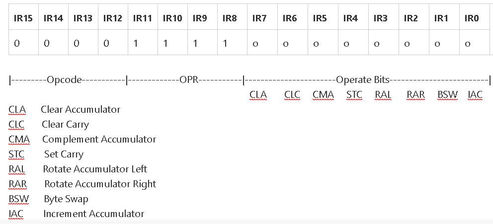
Thirdly, the final instruction slot 0x0Fxx which is currently used as NOP. I intend to extend this to allow for microinstructions - inspired by the OPR, "OPeRate" instructions used on the PDP-8.
Plagiarising the PDP-8
The OPR instructions allow operations such as clearing and complementing the accumulator, setting and clearing the carry bit and shift and SWAP operations to be implemented.
The PDP-8 OPR instructions were implemented with the following individual bit-lines that operated directly on the hardware:
![]()
This scheme gives access to 8 individual control lines which could be sequenced to become active in a specific timeslot which allowed quite complex operations to be performed on the accumulator.
An alternative scheme is possible, where the lower 8-bit payload are fully decoded to allow up to 256 microinstructions. For maximum flexibility this could be done by using the byte to address a micro instruction ROM such as an additional AT27C1024. A 4-bit counter can be used on higher address lines to provide a primitive 16 step microsequencer. That leaves 4 address lines which could be used as inputs to implement a simple external interrupt system.
This would be very flexible but requiring more hardware, and probably quite limited by the access time of the AT27C1024 ROM.
The next plog (project log) will start to look at the hardware architecture and how we might implement a fast microinstruction sequencer using a counter, a diode matrix and some 3-8 line decoders.
-
Hexadecimal Entry
11/02/2019 at 20:29 • 0 commentsIt's been a bit of a slow week, and I must admit that I lost focus in the middle of the week with my hexadecimal number entry routine.
In my opinion, hexadecimal entry is more complex than decimal entry, because the characters 0-9, and A-F are discontinuous in the ASCII table.
Characters 0-9 need to have 0x30 subtracted, whilst characters A-F need to have 0x37 subtracted. Anything else is not a valid hex digit and can be ignored until a newline character is seen.
With each incoming character you have to check if it is a legitimate hexadecimal digit, and modify it, either by subtracting 0x30 or 0x37 to get it's true numerical value.
This test and modify is best done using a short subroutine - at the end of the listing
Once you have the numerical value allocated to the character the rest of the routine is similar to the decimal entry routine, except that you are multiplying by 16 rather than 10.
There's a further twist in the tail when you detect the end of the valid digits and have to add in the last digit - modifying it accordingly.
This first draft allows hexadecimal mumbers up to 0xFFFF to be entered and prints them back in decimal format.
You can find the latest listing for the Arduino in my Github Suite-16 repository
EDIT: I found some redundant code in the main GETHEX routine and have managed to shorten it from 52 to 34 words.
Further optimisation became possible with the test and modify subroutine approach.
As the instruction set currently lacks a shift left instruction, and it's not yet proven that ADD R0, R0 will be implemented in hardware, the routine to multiply the accumulator by 16 is a little cumbersome using eight instructions rather than a possible four.
EDIT: After proving the ADD R0, R0 instruction and fixing a minor bug the routine is now down to 31 words in length.
// 0x003C -----------------------------GETHEX---------------------------- // Accepts a hexadecimal number up to FFFF from terminal input buffer // converts it to an integer and puts it into register R0 // It can then be printed out as a decimal using PRINTNUM - for checking integrity // R1 is the pointer in the text buffer - which starts at 0x0200 // R4 is used as a temporary store for the character in the accumulator R0 // R5 is used in the "Times 16" routine // R7 is used to accumulate the powers of 16 when forming the integer in R0 0x1100, // SET R1, 0x0200 text buffer start 0x0200, 0x1700, // Don't forget to clear R7 0x0000, // 0x0040-------------------------------------------------------------------------------------- 0x4100, // LD AC, @R1 get first character from buffer :Getchar 0x3400, // Store R0 in R4 0xE100, // INC R1 0x4100, // LD AC, @R1 get next character - and test to see if it's a number or hex digit or space newline etc 0x0B30, // Subtract 0x30 Is it bigger than 0x30? 0x0250, // BLT 0x50 Quit No - so must be a space or newline etc 0x0B17, // SBI 0x17 is it bigger than 0x47 ascii for "F" ? 0x0350, // BGT 0x50 Quit Not a hexadecimal digit 0x0853, // CALL 0x0053 Restore, Test and Modify R0 0xA700, // Add in the accumulating total from R7 - ready to multiply 0xA000, // ADD R0, R0 Double R0 2X 0xA000, // ADD R0, R0 Double R0 4X 0xA000, // ADD R0, R0 Double R0 8X 0xA000, // ADD R0, R0 Double R0 16X 0x3700, // Store R0 in R7 R7 is the accumulating total of all the digits multiplied by powers of 16 0x0040, // BRA 0x0040 Get the next digit // 0x0050-------------------------------------------------------------------------------------- 0x0853, // CALL 0x0053 Restore, Test and modify R0 0xA700, // Add the accumulated sum from R7 - integer decimal number is now in R0 0x0010, // BRA 0x0010 Print it in decimal // 0x0053---------------------------------TEST R0 & MODIFY-------------------------------------- // If R0 = 0-9 subtract 0x30 to form a number 0-9 // If R0 = A-F subtract 0x37 to form a number 10-15 0x2400, // Get R0 back from R4 - we now have a hex character in the range 0-F and need to convert it to a value 0-15 0x0B40, // Subtract 0x40 Is it bigger than 0x40? Then subtract 0x37 else subtract 0x30 0x0258, // BLT Not A-F so subtract 30 and return 0x0A09, // ADI 0x09 (restores and corrects R0 to correct numerical value) 0x005A, // BRA Return 0x2400, // LD R0, R4 Get the character back in R0 - we know it's 0-9 0x0B30, // Subtract 0x30 0x0900, // RET 0x0F00, // NOP 0x0F00, // NOP 0x0F00, // NOP 0x0F00, // NOP 0x0F00, // NOP // 0x0060 ------------------------------------------------------------------------------------- -
An Assembler for Suite-16
10/31/2019 at 13:01 • 0 commentsI was delighted to receive a Twitter notification from Frank Eggink, one of this project's followers, with news that he had created a table of Suite-16 instructions so that it can be used by TASM - a table driven assembler popular for small micros about 20 years ago.
His customised table and a link to the dowload site for TASM32 can be found at his Github repository: Here
Many thanks Frank - much appreciated your contribution!
I have re-jigged the instruction set slightly in the last few days - and the most recent can be found in this simulator file in my Github
With the changes to the instruction set, I now have no more empty slots, so the NOP at 0x0F00 seems a bit extravagant.
With an 8-bit immediate add to the accumulator, the NOP can be created from ADI 0.
This frees up the 0x0Fxx slot for my proposed (PDP-8 like) OPR instructions including shifts, clears, complements and small constants.
The main changes are documented in the text header:
// A simple simulator for Suite-16 processor // Add and Subtract Immediate instructions ADI and SBI added at 0x0Axx and 0x0Bxx // IN moved to 0x0D00 // JP@ - Branch to the address held in the accumulator added at 0x0E00 /* Suite-16 Instructions Register OPS- 0n --- -- Non-Register Ops 1n SET Rn Constant (Set) Rn = @(PC+1) 2n LD Rn (Load) AC = Rn 3n ST Rn (Store) Rn = AC 4n LD @Rn (Load Indirect) AC = @Rn 5n ST @Rn (Store Indirect) @Rn = AC 6n POP @Rn Pop AC AC = @Rn Rn = Rn - 1 7n PUSH @Rn Push AC @Rn = AC Rn = Rn + 1 8n AND Rn (AND) AC = AC & Rn 9n OR Rn (OR) AC = AC | Rn An ADD Rn (Add) AC = AC + Rn Bn SUB Rn (Sub) AC = AC - Rn Cn INV Rn (Invert) Rn = ~Rn Dn DCR Rn (Decrement) Rn = Rn - 1 En INR Rn (Increment) Rn = Rn + 1 Fn XOR Rn (XOR) AC = AC ^ Rn Non-register OPS- 00 BRA Always Target = IR7:0 01 BGT AC>0 Target = IR7:0 02 BLT AC<0 Target = IR7:0 03 BGE AC>=0 Target = IR7:0 04 BLE AC<=0 Target = IR7:0 05 BNE AC!=0 Target = IR7:0 06 BEQ AC=0 Target = IR7:0 07 JMP 16-bit Target = @(PC+1) 08 CALL 16-bit Target = @(PC+1) 09 RET Return 0A ADI Add 8-bit Immediate Immediate = IR7:0 0B SBI Subtract 8-bit Immediate Immediate = IR7:0 0C OUT putchar(AC) 0D IN AC = getchar() 0E JP@ BRA (R0) 0F NOP AC &= AC */ -
Immediate Instructions
10/29/2019 at 13:14 • 0 commentsOne of the deficiencies with the Suit-16 instruction set was a lack of an immediate addressing mode, where one of the operands is contained in the next word in memory.
This specifically was becoming a problem when you wanted to check if the contents of the accumulator lay between two bounds - and branch accordingly. This type of test is frequently found in ascii to hex or decimal conversion routines and string handling, and after coding a few routines it became obvious that the current situation involving other registers was clumsy and inadequate.
As a compromise I have added two instructions ADI and SBI which allow an 8-bit value to be coded into the payload area and have it added to or subtracted from the accumulator.
I have coded these two instructions in the spare 0x0Axx and 0x0Bxx instruction slots to try them out and see if they make coding easier and less convoluted. If they are useful they will get added to the final instruction set that will be implemented in hardware.
Here's an example from the Number entry routine where the input character needs to be tested to find out if it falls between ASCII 0x30 and 0x39 and is therefore a decimal digit. Registers R2 and R3 are first preloaded with the constants 0x0A and 0x30 so that they are available for the tests. These preload instructions will not be needed, saving 4 words of memory, and the SUB R3 and SUB R2 instructions become SBI 0x30 and SBI 0x0A respectively.
Whilst this might seem a trivial change in this example, it will be very useful when testing the input buffer for certain known strings - essential for dealing with high-level languages with keywords.
0x1300, // SET R3 0x30 Preload R3 with decimal 48 0x0030, 0x1200, // SET R2, 0x0A Preload R2 with decimal 10 0x000A, 0x1100, // SET R1, 0x0200 text buffer start 0x0200, 0x4100, // LD AC, @R1 get first character from buffer 0x3400, // Store R0 in R4 0xE100, // INC R1 0x4100, // LD AC, @R1 get next character - and test to see if it is a number 0xB300, // Subtract R3 Is it bigger than 0x30? 0x025A, // BLT Not a Number 0xB200, // Subtract R2 0x0A 0x035A, // BGE Not a Number 0x2400, // Get original character R0 back from R4 0xB300, // Subtract R3 to form a digit -
Benchmarking Suite-16
10/28/2019 at 13:46 • 0 commentsOver the last week I have been running Suite-16 assembly language simulated in about 60 lines of C++ code. I have evolved the simulator over that time, and added some new instructions where it became necessary to use them.
The simulator has been written using the Arduino IDE - so that anyone with an Arduino compatible board can explore the code and learn how a very simple cpu simulator works.
Originally I had been simulating the Suite-16 cpu on an MSP430 Launchpad board with FRAM.
I noticed that despite it being a 16-bit processor, the performance was not so good, so I have swapped over to a Nucleo STM32H743 board which has a 400MHz ARM processor.
I'm still using the Arduino IDE to develop code - because it has a useful timing function micros() which returns the number of microseconds since the program was started. With this I can get fairly accurate timing information from my simulator.
I have used one of the spare instruction opcodes to allow the instruction count and the elapsed time to be output to the terminal
By way of a timing benchmark, I have set up a simple loop that loads R0 with 32767 and repeatedly decrements it until it reaches zero. I then print out instruction count and elapsed number of microseconds.
Based on the "count down from 32767" loop, my Suite16 simulator is running about 8 million simulated instructions per second.
That's about 66% of what I'm hoping the TTL cpu to run at.
Based on the 400MHz clock on the Nucleo board, I can estimate that the simulator in C is taking about 50 ARM instructions to execute a Suite-16 simulated one.
I tried exactly the same code on the MSP430 which is a nominal 16MHz. Unfortunately the FRAM only works at 8MHz with wait states, so that slows it down considerably to about 75,000 simulated instructions per second.
So I tried a 16MHz Arduino with an 8-bit AVR ATmega328 and the results were much improved to nearly 139,000 instructions per second.
The humble AVR is approximately 59 times slower than the ARM, but with a 7uS simulated instruction cycle it is still in the same league as some of the classic minicomputers from the 1960s.Update 31-3-2021.
I am now running the simulator on a 600MHz Teensy 4.0 dev board.
An empy loop executes at around 50 million iterations per second and an addition, subtraction or logic operation can be performed around 9.2 million times per second.
I have decided that the ISA of Suite-16 is a very good match for a stack-based bytecode language called STABLE by Sandor Schneider.
-
Stack Operations
10/26/2019 at 12:21 • 0 commentsCharles Moore's Forth is based on a 16-bit virtual machine that passes parameters between functions using the Parameter Stack (also known as Data Stack).
A stack is just a Last In, First Out (LIFO) structure contained in consecutive memory locations. The stack is often placed in the top of memory and grows downwards. So the top of the stack (TOS) is the lowest in memory of all stack items.
A register or zeropage variable acts as the stack pointer and is pre-decremented when an item is pushed onto the stack, and post-incremented when an item is popped off the stack. The stack pointer always points to the Top of Stack.
Suite-16 has PUSH and POP operations that may be used with any of the general purpose registers - so multiple independent stacks can be created. The only overhead is the assignment of a register solely as use as a stack pointer to one stack and a suitable section in memory. The stack pointer register should be initialised to it's upper boundary value - for example 0x2000 in RAM.
The contents of the accumulator R0 are pushed to the memory location addressed by Rn, after Rn has been decremented. Similarly the top member of the stack is popped into the Accumulator and then Rn is incremented.
The other use of stacks is to hold the return address of subroutines. When a subroutine is called the PC is pushed onto the top of the return stack, and popped back to the PC when a return instruction is executed. With this stacking arrangement it allows for the automatic nesting of subroutines.
Here's how the PUSH and POP instructions are coded on the simulator:
case 0x6:   R[0] = M[R[n]]  ; R[n]= R[n]+1   ;  break ; /* POP with post-increment of pointer Rn */
case 0x7:   R[n]= R[n]-1    ; M[R[n]] = R[0] ;  break ; /* PUSH with pre-decrement of pointer Rn */
M[R[n]] is word in RAM pointed to by the stack pointer R[n] R[0] is our accumulator.
The other instructions that use a stack are the CALL and RETurn: Here R[15] is dedicated as the Return Stack Pointer RSP.
case 0x8:  R[15]= R[15]-1 ; M[R[15]] = PC ; PC = addr ; break ; // CALL (zero page) use R15 as RSP
case 0x9:  PC = M[R[15]]  ; R[15]= R[15]+1            ; break ; // RET
A later log will look at the stack manipulation words such as DUP, DROP, SWAP, OVER that are frequently used in Forth.
Suite-16
Suite-16 is a 16-bit cpu built entirely from TTL. It is a personal exploration of how hardware and software interact.