 Valentin
Documentation:
Want to know how to use the board? Check out the ESP-IDF component API.
Want to know more about the supported boards? Have a look at the documentation.
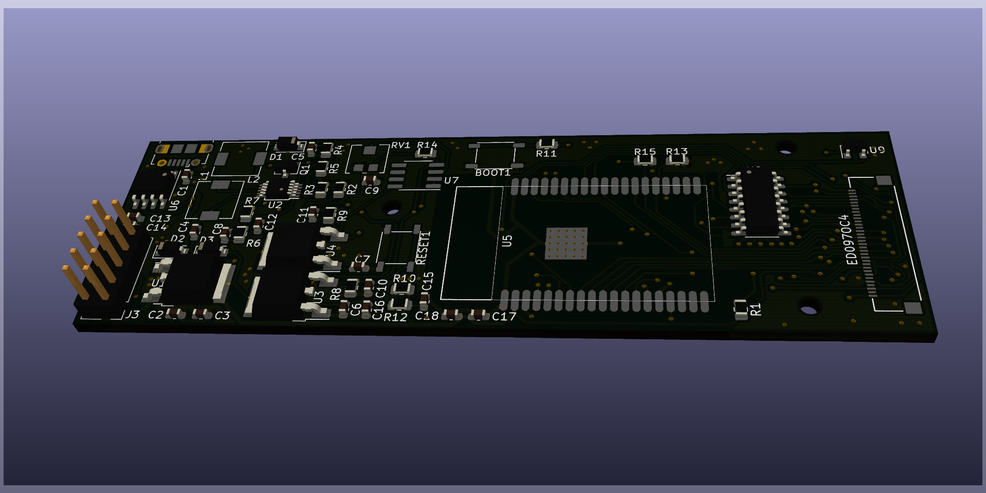
Build It!
KiCad-Project, Gerber files and firmware can be found on github: https://github.com/vroland/epdiy.
Features:
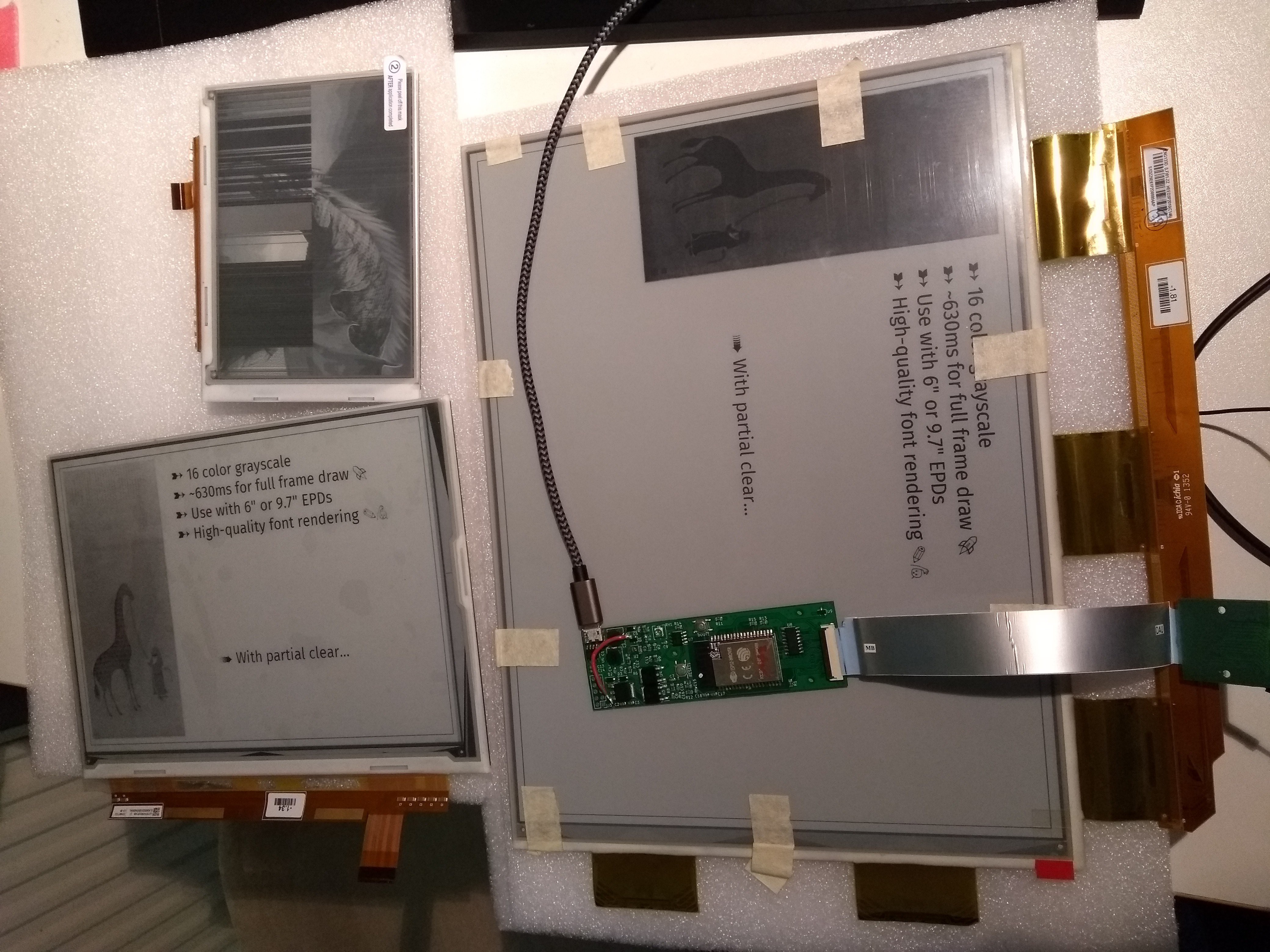
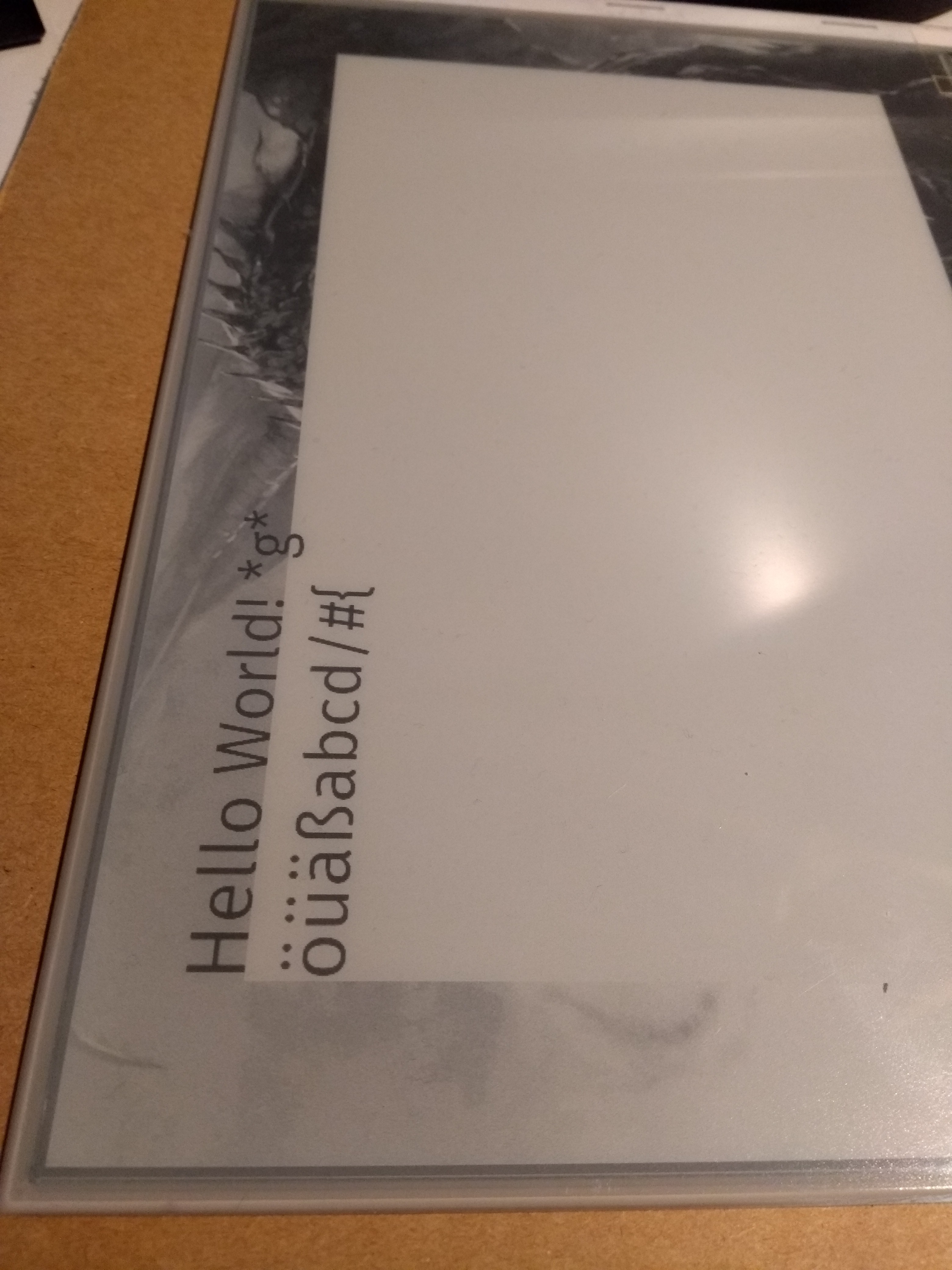
- 4bpp (16 color) output in ~500ms (at 1200x825 resolution, faster for partial updates)
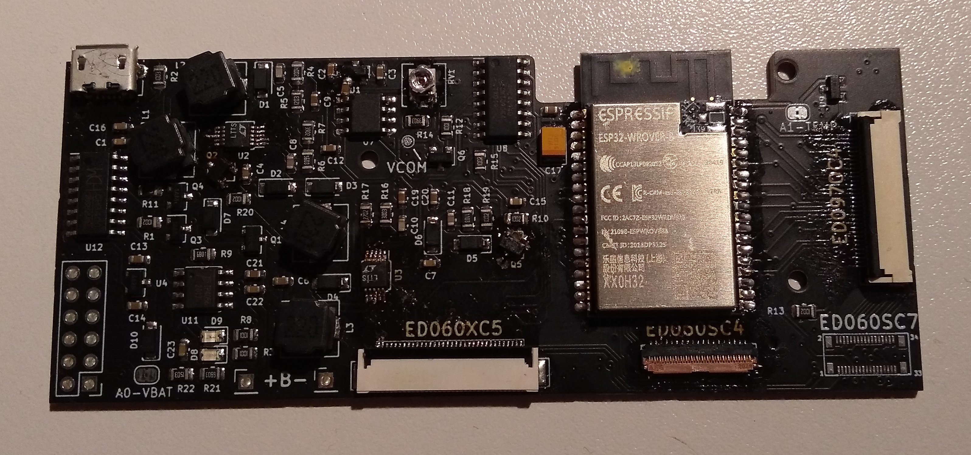
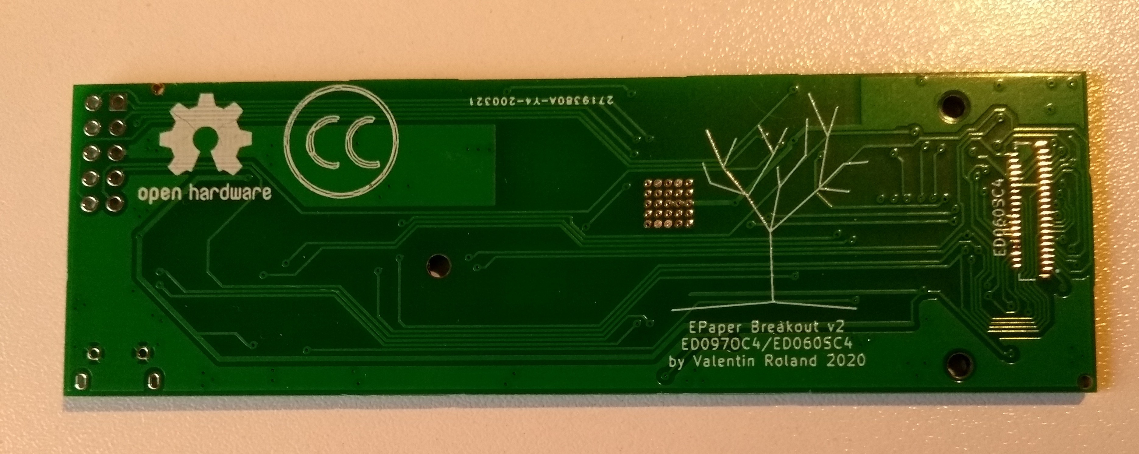
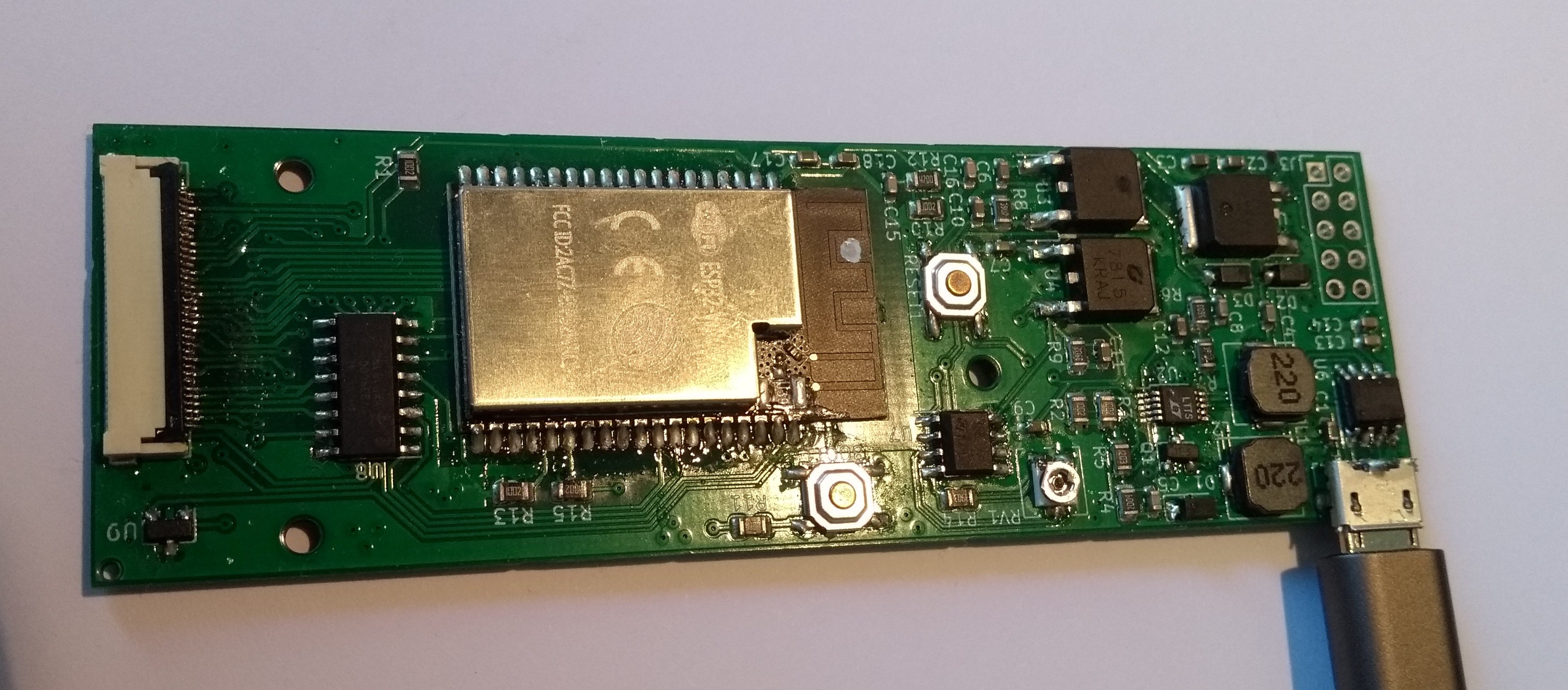
- Simple, 2 layer PCB with all components on front (Optional connector for 6" EPDs on the back)
- Small form Factor
- Onboard temperature sensor
- Broken out SPI and sensor pins
- High-level library for own software (https://epdiy.readthedocs.io/en/latest/ This is still work in progress!)
Thanks to:
Thanks to the work of some awesome people, the hard stuff was already done:
- #PaperBack: A Desktop EPaper Monitor is a great project using the ED060SC4, 6" screen. Though for a much smaller display (see comparison in the gallery), I could re-use the power supply scheme by @PK.3.
- #NekoCal - an E-Ink Calendar uses the same 6" display as PaperBack. Their color rendering method proved to work very well for this project. Additionally, the project as a great writeup on how to do it!
- http://essentialscrap.com/eink/waveforms.html One of the earliest ePaper hacks out there? Has great descriptions on how to drive these displays in general.


 daniel.bryand
 Jeff Cooper
 j0z0r pwn4tr0n
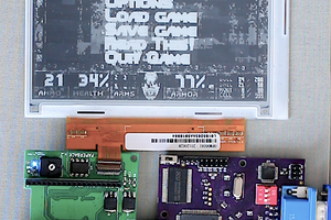
 PK
PK
I play in a little orchestra and others are using a big ipad, or a usb c external monitor for displaying their music sheets. I always have thought maybe an e-ink display would be nice for this usecase. 13" are perfect .
But it seems those model numbers are not being sold anymore.
Do you have any information where I could look for alternatives?