Cheap-O-NAS
A low-cost solid-state NAS with power-loss protection
A low-cost solid-state NAS with power-loss protection
To make the experience fit your profile, pick a username and tell us what interests you.
We found and based on your interests.
NAS_UPS_v3.ascImprovement on the dc-dc converter-based design, with a second MOSFET to drive the enable line.asc - 6.81 kB - 12/01/2019 at 09:58 |
|
|
NAS_UPS_v2.ascVersion which uses a dc-dc switcher module (with ENable) instead a P-chan MOSFET.asc - 5.91 kB - 11/15/2019 at 15:53 |
|
|
NAS_UPS.ascUpdated to use actual MOSFETs I intend to use. The low gate voltages do make a difference to the choice of parts...asc - 4.67 kB - 11/04/2019 at 15:52 |
|
Two days ago the worst thing happened: I tried to access the NAS over the network and couldn't.
I could log in to OMV ok, and interrogated the setup only to discover both Main and Backup filesystems weren't mounted (or mountable) and even the disks themselves were there one minute and gone the next. Everything was very flaky for a while before eventually I had nothing. Occasionally one disk could be mounted for a few seconds and then gone again.
Suspecting (wishing?) the SATA-to-USB adaptors to be the cause, I plugged one of the disks directly into my Windows PC to discover a perfectly healthy disk with an empty, unformatted partition! Eeeeeek! Thankfully, after some searching, it seems Windows doesn't like something about Linux partitions - something to do with GPT, EFI, or whatever...
Plugging the disk, via the duff adaptors, into an old Linux laptop I have confirmed it: one of adaptors did pretty much nothing, the other one repeatedly power-cycled the disk - as evidenced by dmesg logs. For a brief moment, it actually worked, the disk mounted ok and I saw my files! Phew! ...and then it was gone again.
So, two new (much more expensive, branded and guaranteed) SATA-to-USB adaptors later, and everything is back to normal. The lesson: don't buy £5 adaptors from eBay - they are cheap crap that don't work for long.
[PS. I cracked open the case to find a board with a chip marked "JMS578". Comparing the markings on the chip and on-line photos of the genuine JMicron part makes me think this chip is a fake - the typeface isn't the same and it's been laser-etched on. Maybe I'm just paranoid.]
Two months ago I changed around how the power supply works and completely forgot to document it here! Oooops. So, better late than never, here it is:
You can see a new bit of Veroboard with a couple of MOSFETs on to do the signalling, the red board is an 'ideal diode' module from eBay, and the blue board is a modified dc-dc converter module.
The net result is that the voltage regulation is now much better, and the NAS has been performing faultlessly ever since - despite numerous unexpected power cuts.
The LM2596-based module I bought is, of course, a fake. Apart from the dodgy laser-etched case markings, the switching frequency is only 55kHz instead of 150kHz. So now I have to find a real LM2596 and transplant it onto the board, or else risk the fake part not quite being reliable enough.
In the meantime, I've increased the main PSU voltage by a couple of 100mV, and now the RPi is quite happy and doesn't have as many low-voltage warnings.
Maybe I'll park the 'upgrade' idea for a while and see if I still need it...
The Cheap-O-NAS has been running great for the last few weeks, and I've no major complaints. However, it's not quite perfect. A couple of times, I've pulled the power and it hasn't shut down properly and ended up flattening the batteries completely. And on one occasion it didn't boot up properly.
The immediate problem is that the voltage regulation (for the main supply and the battery backup) is quite poor, so the Pi is regularly detecting low-voltage conditions, especially when the disks are thrashed. This can't be healthy, and probably leads to all sorts of odd, unexpected conditions arising.
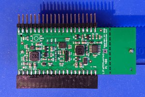
The solution is to re-architect the supply circuit, putting a dedicated 5V dc-dc supply right next to the Pi, and powering it all from a much higher voltage (e.g. 12V). A suitable switcher has been identified, only requiring a minor modification to bring its nENABLE pin off the board, so that the supply can be shut down. The whole circuit is much simpler than before, only requiring two transistors and five resistors (plus the supply OR-ing diodes).
I managed to 3D print a case with aluminium sheet lid and base. All the bits fit neatly inside with only connectors for power and ethernet - sweet.
Success at last.
The latest incarnation of the circuit seems to be much better: the signals to/from the Pi are now separated and behave themselves, and the dc-dc converter is definitely off (<1uA current) normally.
The 3 second delay prior to shutting down still isn't working, but maybe that's an OS problem that will eventually get fixed in some later update... For now, I think it's safe to use as a NAS will real data on it!
I've now got an 'ideal diode' module, so will try swapping it for the main Schottky so that the supply voltage doesn't bump up and down so much with load current.
I've found that with a screen plugged into the HDMI output, when pulling the power the RPi instantly reboots. Without a screen, the RPi correctly shuts down cleanly as intended by the gpio-shutdown overlay. No observable difference can be seen in the 'scope traces of the power supply for these two situations, so the rebooting is not being caused by my power management circuit, I don' think.
- why the heck should having an HDMI screen plugged in make any difference?!
Also,
dtoverlay=gpio-poweoff,gpiopin=27,active_low=1
...works and the Pi drives it from high to low after shut down. But
dtoverlay=gpio-poweoff,gpiopin=27,active_low=1,input=1
...with the pin as an input normally does not for some reason. The pin correctly turns into an input (apparently without the pull-up I was expecting it to have), but doesn't get driven low after the Pi has shut down. Instead the Pi instantly restarts without shutting down.
However, disconnecting my circuit, and pulling GPIO27 up to 3V3 with just a resistor does work. A low is seen just after (proper) shut down. I suspect somehow GPIO27 is triggering GPIO17 which is programmed to shut the Pi down!
Check the files for a v3 LTSpice circuit with an extra MOSFET switch. This isolates PGOOD from nSHDN to solve this problem, and also drives the ENable (to ensure the dc-dc module is properly off in normal use).
I ended up modding the mains power supply to produce ~5.5V instead of ~5.0V so that downstream of the Schottky the supply rail was about 5V. Now, when the main supply is pulled, the Pi no longer immediately restarts. Instead, it appears to initiate the shutdown as intended. There are still some problems though:
- the 'debounce' part of the dtoverlay doesn't seem to be working, as it begins shutting down immediately rather than after a couple of seconds
- the GPIO pin that is meant to drive low after shutting down doesn't appear to do anything, so the power never gets turned off
- in normal state, the dc-dc converter isn't quite fully off (the EN line is at about 1.3V) and seems to be sucking ~1mA instead of the ~0.2uA I get when EN is pulled to 0V properly. That will flatten the batteries in no time... [edit: EN needs to be less than about 0.9V for the standby current to be around 0.2uA]
Still more to be done then!
Just found this: https://www.raspberrypi.org/forums/viewtopic.php?t=50470
Kinda very relevant, but no mention of the Pi restarting at the instant the main and backup supplies switch over. Maybe earlier versions of the Pi don't have brownout resets?
Oh, and then there's this: https://thepihut.com/products/ups-pico?variant=20063191203902
...which I could just buy. :(
The RPi4 seems to use the MxL7704 PMIC, instead of the APX803 supervisory IC used in earlier versions. The 7704 does not have a brown-out reset line, so for my Pi to be resetting itself, something must be triggering that reset indirectly by monitoring the PGOOD lines. It's probably not helped by the supply already being low enough for the lightning bolt to be showing (<4.65V), likely due to the drop across the Schottky. I'll have to get the thing hooked up to a 'scope to see how big the glitch is. Adding 1000uF to the 5V rail did not cure it.
Last night I finally plugged everything in together for the first time. I had lots of problems getting the Pi to boot properly and produce an HDMI signal so I could actually see what was happening. Eventually I got it sorted, and was able to configure OpenMediaVault. Halfway through trying to set up the two disks as RAID1 I seemed to have more problems, and then stumbled across lots of stuff about RAID1 being effectively useless when used with USB disks (presumably due to the need to share the bus, rather than having independent controllers like SATA - IDK, I'm not an expert). I also thought a bit more about what I actually want the NAS to achieve, and maybe RAID isn't it.
So tonight I'll start again. This time I'm going to ignore RAID altogether, and set up a Main disk and a Backup disk, and use OMV to schedule automatic, incremental backups of one onto the other. So I kind of get the dual redundancy I wanted, as well as some protection against human error like accidentally deleting files.
Oh, ps. the fail-over power didn't quite work. Upon pulling the plug, the Pi instantly rebooted. But at least that means the batteries had taken over and were able to supply the power required. I guess the Pi's SoC has a brown-out detect that got triggered by some minute glitch. Something to fix later.
Follow the instructions in this excellent video which shows you how to install OMV on a Raspbian Buster Lite OS.
I cannot emphasise enough the need to use a microSD card from a reputable source (e.g. physical shop). I have wasted hours on this project battling with low quality and/or fake cards! There, I told you.
Probably best not to use the RPi4 image on the OMV website, as the folk on there point out that it's based on an unsupported Armbian OS.
Also, before plugging the microSD card in, write a blank file called "ssh" to the /boot folder, to enable ssh without needing a keyboard and screen plugged in. This saved me heaps of time!
Once OMV is installed, do all the updates, configure the disks/shares etc. according to the OMV documentation.
ssh in and edit /boot/config.txt using e.g. pico:
sudo pico boot/config.txt
...then add the following two lines to the end and save:
dtoverlay=gpio-shutdown,gpio_pin=17,active_low=1,debounce=1500
dtoverlay=gpio-poweroff,gpiopin=27,active_low=1,input=1
While you're at it, maybe consider commenting out some of the other unwanted stuff, like audio and 3D support.
In conjunction with the little circuit I described, PGOOD and nSHDN connected to pins GPIO17 and GPIO27 respectively you should be protected against power outages.
I had loads of problems with the NAS appearing and disappearing from remote connections (e.g. from Windows), pausing during audio/video playback, hanging, etc. It seems that the SSDs were not happy, and getting repeatedly reset. This article explains what to do in detail.
tl;dr version here:
Edit boot/cmdline.txt and add the following to the start of the line that's there:
usb-storage.quirks=aaaa:bbbb:u
...where aaaa and bbbb are the idVendor and idProduct codes for your SSD(s).
Create an account to leave a comment. Already have an account? Log In.
Hi, that's a really top tip - I hadn't considered the accumulation of log files. I will definitely follow that up, thanks. In any case though, ultimately my data will be safe, even if I have to go through the hassle of building a new SD card image and doing all the updates just to get the NAS functionality back in the event of a card corruption. I'll keep posting back here with updates on how it's going...
Become a member to follow this project and never miss any updates
By using our website and services, you expressly agree to the placement of our performance, functionality, and advertising cookies. Learn More

 Patrick Van Oosterwijck
 Paul Crouch
 alcor6502
 alnwlsn
Not sure how much experience you have with the PI, but really interested in your project, and hoping you have great success. One thing I would like to point out, is the SD card will defiantly be a weak point of failure for you, but you can extend this MTBF (Mean time between failure) by writing out the logs to RAM, and then dumping the RAM to disk at a given interval. The write-up on hack-a-day works well https://hackaday.com/2019/04/08/give-your-raspberry-pi-sd-card-a-break-log-to-ram/ . I made a login just to post this comment :) Good Luck!