 Adam Demuri
The final Colordance 2.0 installation will have a main control board in a podium. This board will control the main bright LED panels, as well as standard strips of LEDs on the outside (for visibility). There will be six poles, each having a bright LED array and an LED strip. To reduce the risk of failure, the bright LEDs and LED strips will be driven separately. This means that the main control board will need to drive twelve strings of lights. The poles will be 10 feet tall, and be situated in a circle 15 feet in diameter, so the line between the control board and the LEDs could be up to 30 feet.
The WS2812 protocol isn't designed for long distances like this. I couldn't find many people on the internet who had done this (successful or no). We decided that it was best to reduce risk by using a different hardware transport for the signal between the control board and the poles. I chose RS422 because it supports a high enough datarate (WS2812 is 800khz), and because it is differential, so it has good noise immunity and can support long lines.
Note that RS422 and RS485 are similar. Each RS422 line is one-way, with a fixed transmitter and receiver. RS485 allows multidirectional communication by tri-stating when not transmitting. Since we only need one-way communication, either kind of transceiver will work.
I used capacitive termination for the RS422 line. See this application note for details. This worked fine with my ~25ft ethernet cable, and the scope traces looked fine. We're likely to need some termination at our cable length and data rate. However, using a 120 ohm resistor means that each RS485 line will burn a moderate amount of power. Capacitive coupling means that it will only consume power when the line is active (and even, much less). I used 1300pF capacitors.
I started with the receiver boards. Here are the requirements for these boards:
- Take a 12V supply
- Supply 5V 1A, to power the strip lights
- Supports two WS2812 signals over RS422
- Has hookups for connecting PIR (motion) sensors from pole to control board
I used Ethernet (with RJ45 plugs) to transport the signal. I'm hoping that these will be relatively robust (a concern for art that lives outside, especially for Burning Man).
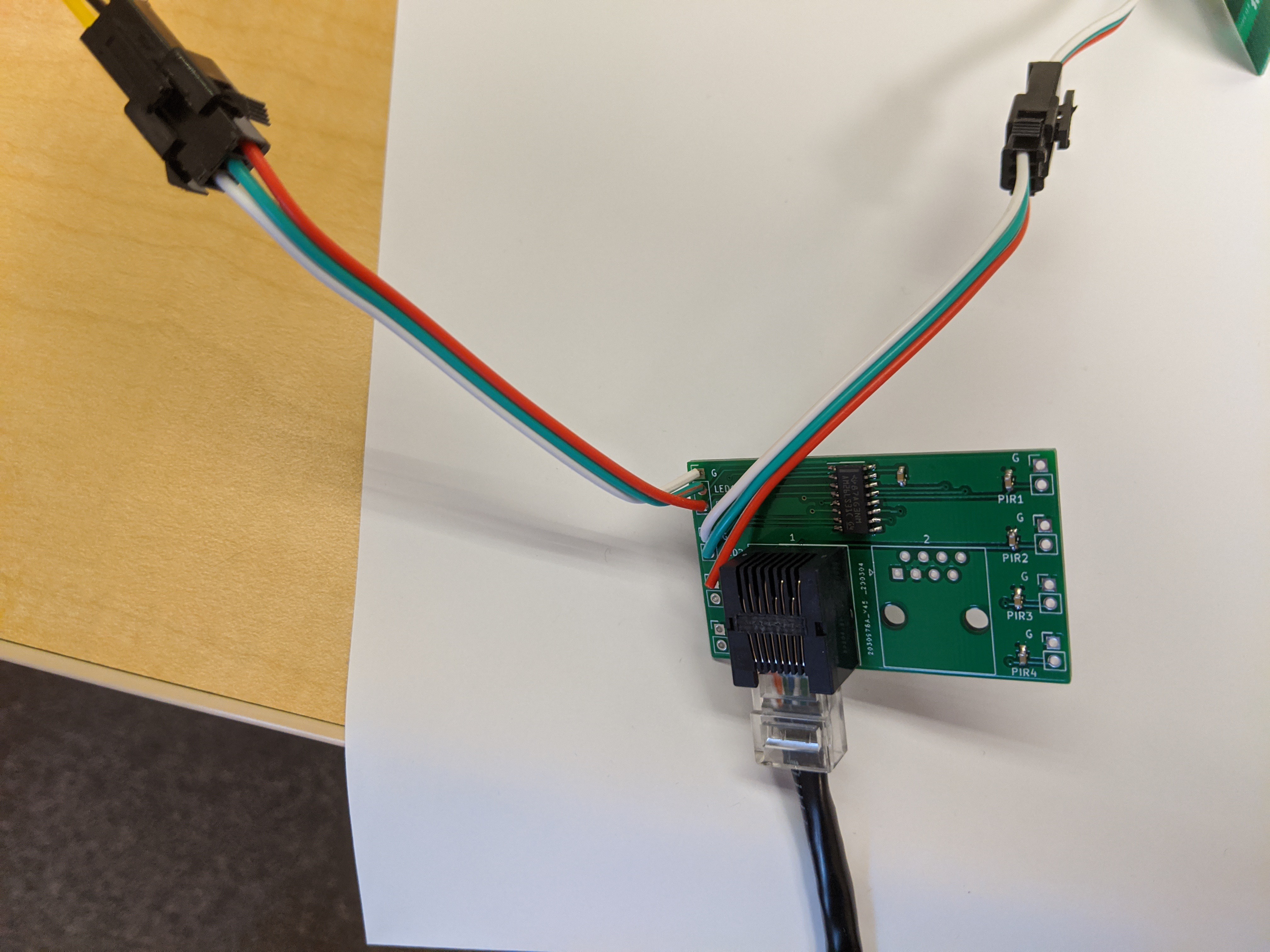
Here's the receiver board:
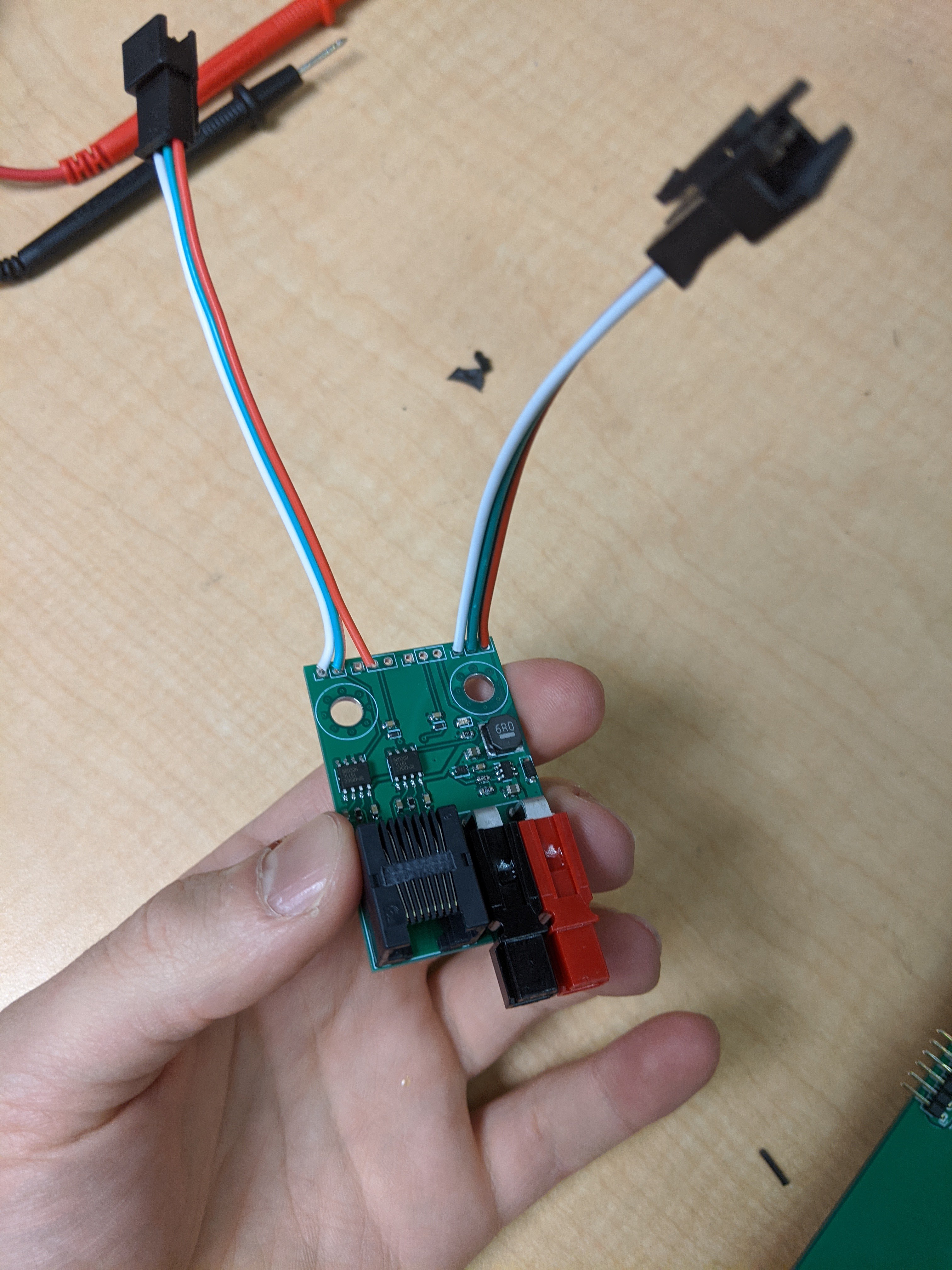
See the design files here.
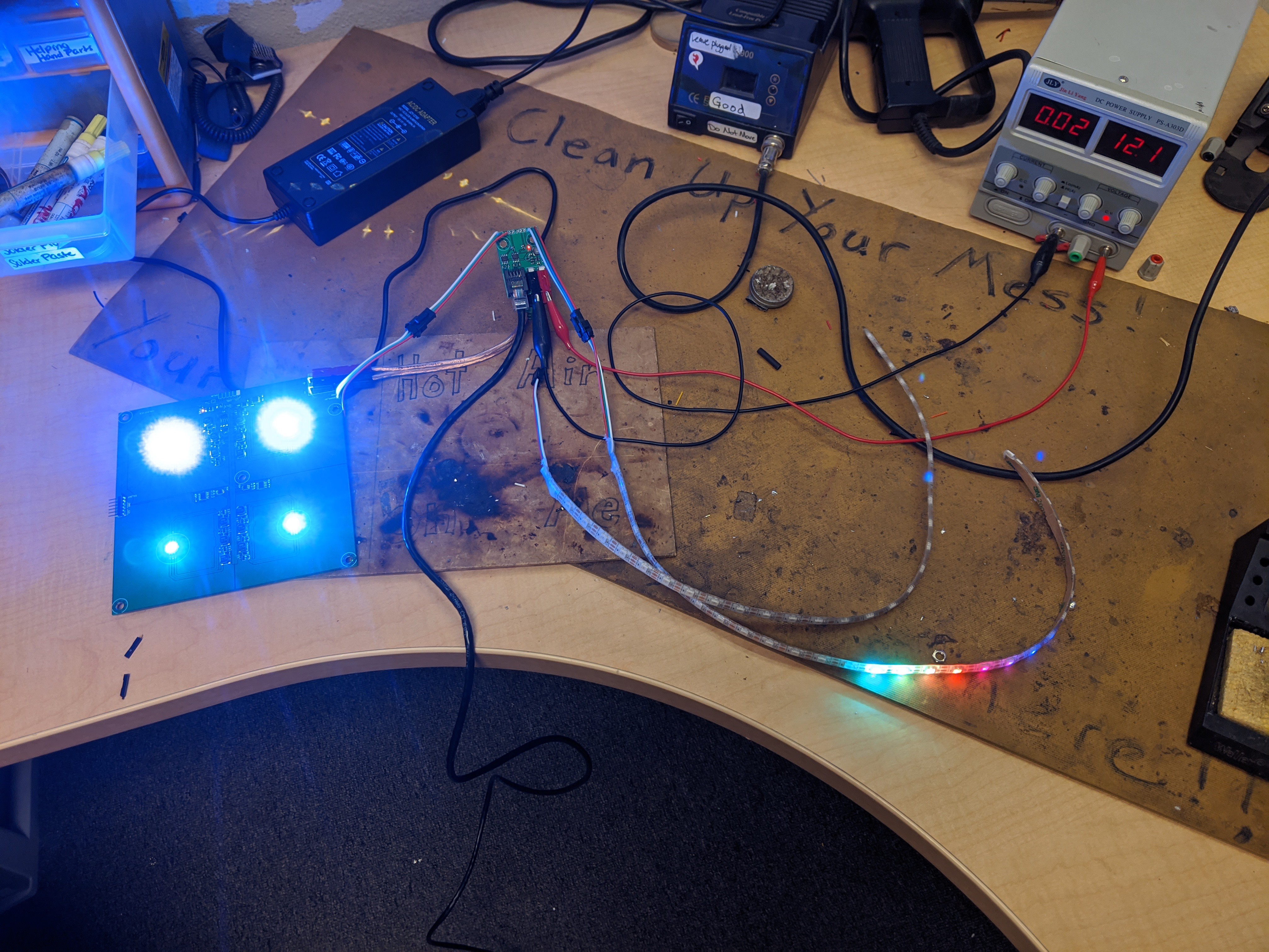
And hooked up to an LED strip and a 2x2 LED panel:
I also designed a simple transmitter board for testing. The RS422 driver I plan to use on the control board has 4 driver channels - I designed the transmitter test board to use all of them, just in case.
Design files here.
Termination Testing
I captured oscilloscope traces of the RS422 signal, to make sure that the capacitive termination works. On these captures, the red line is the actual differential signal - that is, it's the difference between the A and B lines (teal and yellow). First, here is the signal measured at the RJ45 jack of the transmitter - you can see that there's just a little bit of ringing and capacitance, but it's pretty clean:
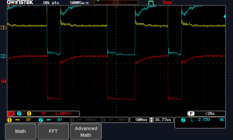
Now, here's the receiving end:
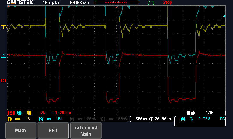
Not quite as nice, but still totally fine. Lastly, here's the output of the board:
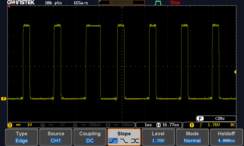
Nice and clean!
Power Consumption
Theoretically, the capacitive coupling will consume more power when the line is changing. I roughly tested this using a USB multimeter with a resolution of 10 mA. I programmed the sender to write out 100 LEDs about every 10ms. The increase in power consumption was less than 10mA. That's good enough for my purposes.
Discussions
Become a Hackaday.io Member
Create an account to leave a comment. Already have an account? Log In.
This is awesome. I've been wanting to do something like this for ages (ever since struggling with signal integrity for a playa project years ago). Thanks for publishing the design files!
Are you sure? yes | no