 Christoph Tack
The problem
During charging Li-Ion, the battery must be disconnected from its load, otherwise the charging algorithm won't work correctly. At the same time, the load must still remain powered.
The traditional solution
As also shown in MCP7383X Li-Ion System Power Path Management Reference Design, the easiest solution is to use a diode, a resistor (10K in this case), and a PMOS.
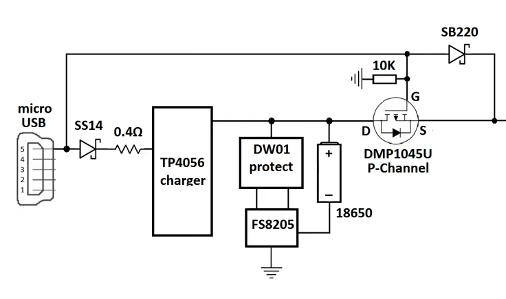
The problem with this approach is the power loss and voltage drop over the diode. Another problem is that the load may require periodical large currents that the USB-power supply can't handle. Even if the battery holds enough charge to deliver that current peak, it's disconnected from the load.
The sensible solution
TI has solved the problem for us : bq2403x Single-Chip Charge and System Power-path Management IC and it includes a charger as well.
The alternative solution
Ideal diode circuits exist. These "diodes" have a very small forward voltage, but typically a high leakage current. So making them unsuitable for battery operation.
The ideal diode solution : DIY
Using COTS parts
[Burgduino] used an LM66100 as ideal diode controller. Unfortunately it only allows for 1.5A or so and it's a single-source solution. To make matters worse, it's currently (Q1 2022) unobtainium.
Alternative parts are the Torex XC8111AA01MR-G (unavailable March 2022), or the Analog Devices MAX40203ANS+T (unavailable March 2022).
To handle larger currents, more of these parts would have to be put in parallel.
Using discrete parts
The ideal-diode problem is harder than it looks at first sight. Consider we want to use two mosfets: one for the usb-path and one for the battery path.
Either one of these mosfets should be on at any instant in time. It's also allowed that both mosfets are off, but for a short period of time to limit heating in the internal diode.
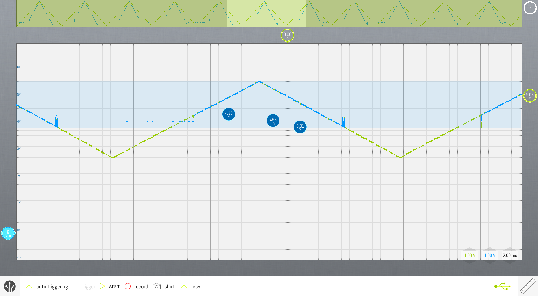
When does the battery-path mosfet need to turn off? Before the usb voltage rises above the battery voltage. Otherwise current from usb will drain away to the battery.
When does the usb-path mosfet need to turn off? Before the usb voltage drops below the battery voltage. Otherwise battery current will drain away to the usb circuitry.
A little bit of hysteresis generally improves stability on a comparator. In this case, hysteresis should be limited because it causes the usb-path and the battery-path to conduct simultaneously.
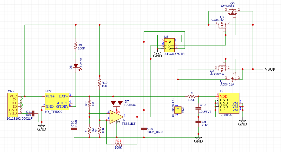
U7 is a push-pull comparator which compares half of the battery voltage to half of the USB-voltage.
The battery voltage is sampled using R11 and R18. Because they're always draining the battery, they have a large resistance. The high-impedance pin 4 of U7 becomes very susceptible to noise. C30 effectively filters the noise on that node.
The usb voltage is sampled with R19/R20. These have a much lower resistance than R11/R18, to increase reaction speed to changes in usb-voltage.
R21 is the feed-forward resistor, causing a ±470mV hysteresis. It might not be needed, but it's easier to leave it not-placed than to add it.
The output of the comparator either switch Q3/Q5 ON or Q6/Q7. You could use single mosfets if you need to switch lower currents. Any 3401-mosfet will do.
The 3157-analog switch is wired as an inverter.
The 881-comparator, 3401-mosfet and 3157-analog switch are generic parts which can be sourced from multiple vendors.
Additional components are a TP5000-charger module and a IP3005A battery protector. These are single source 😢.
Discussions
Become a Hackaday.io Member
Create an account to leave a comment. Already have an account? Log In.