0%
0%
X60s (2020) ThinkPad
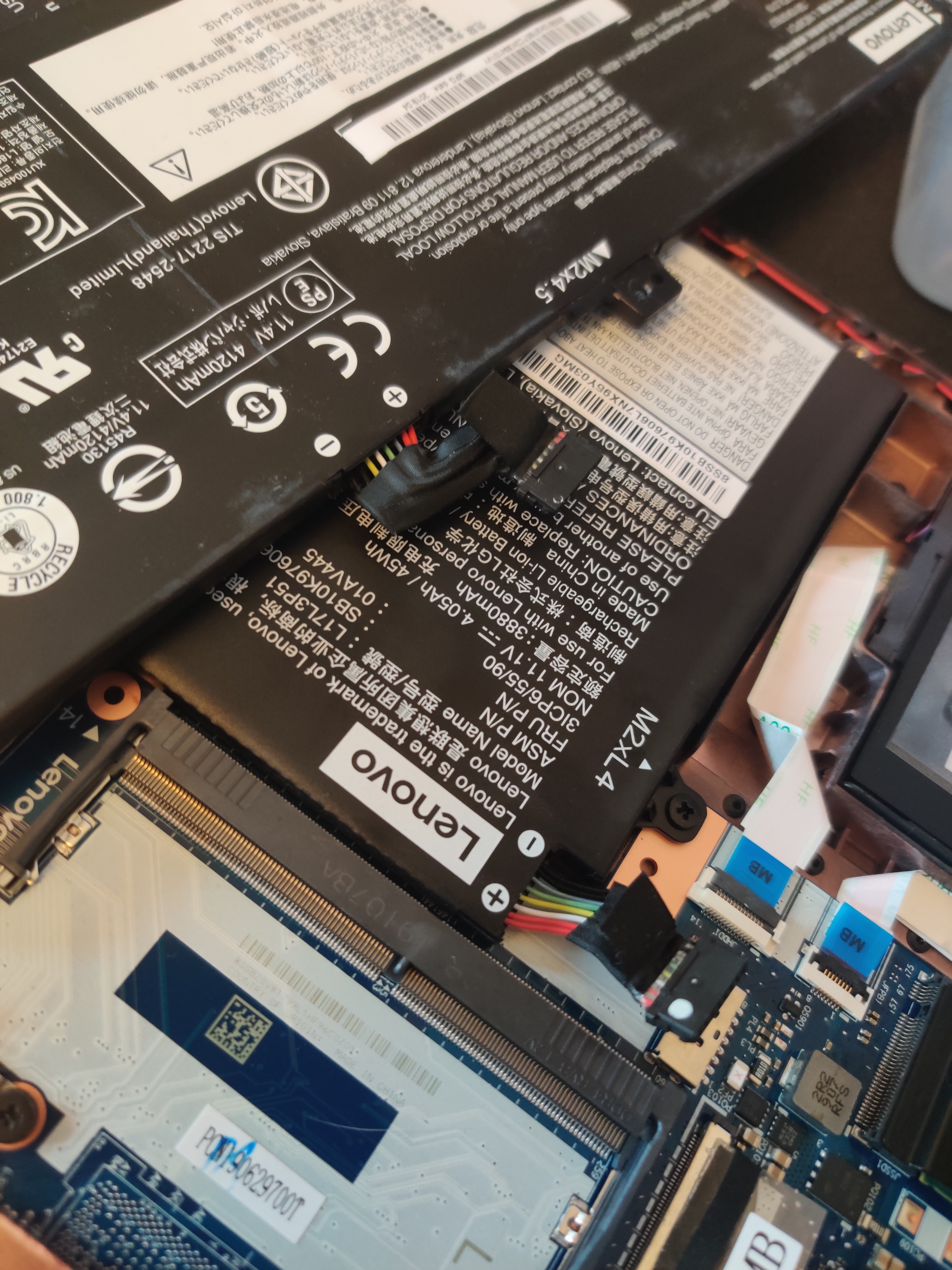
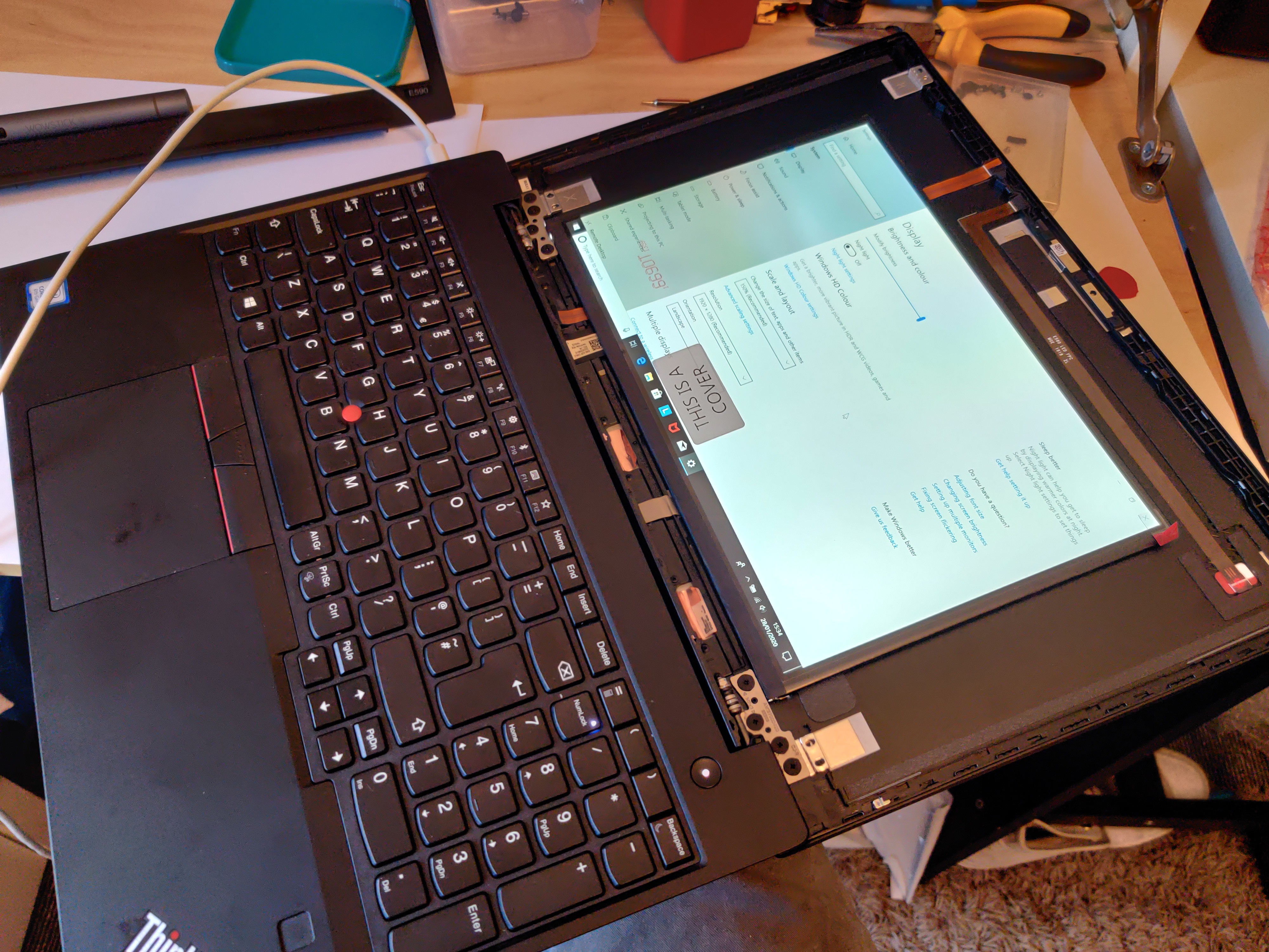
X60s is a near-perfect laptop chassis for mobility. I will be retrofitting a modern laptop motherboard to modernize this machine
 Sean
SeanBecome a Hackaday.io member
Already have an account? Log in.
Just one more thing
To make the experience fit your profile, pick a username and tell us what interests you.
Pick an awesome username
hackaday.io/
Your profile's URL: hackaday.io/username. Max 25 alphanumeric characters.
Pick a few interests
Projects that share your interests
People that share your interests


 Dixbit
 Solderking
 Dan Julio
 Kumar, Abhishek