 land-boards.com
Features
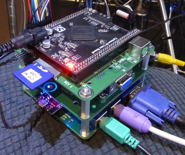
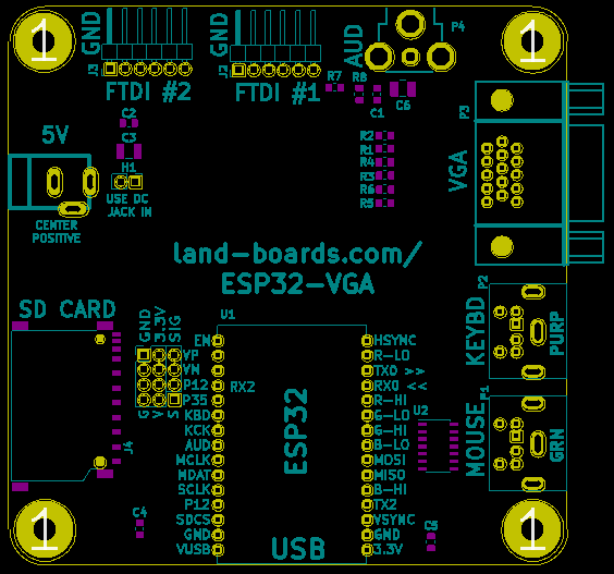
- ESP32 Module
- 6-bit VGA color
- 2 x PS-2 DIN connectors
- 5V mouse/keyboard
- 3.3V to 5V level shifters
- 10K pull-ups on both sides
- 2 x FTDI connectors
- 5V DC Jack
- 3.3V regulator (optional)
- GVS pins for extra ESP32 pins
- 95x95mm form factor
- 6-32 mounting holes
FabGL
- Fabrizio Di Vittorio's FabGL library
- Arduino IDE compatible development
- Display Controller (VGA, SSD1306)
- PS/2 Mouse and Keyboard Controller
- Graphics Library
- Sound Engine
- Game Engine
- ANSI/VT Terminal


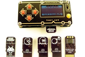
 bobricius
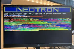
 Jonathan 'theJPster' Pallant
 Keith
Keith
I've seen others do the ESP8266 driving VGA. Google "ESP8266 VGA" shows several projects out there.
I don't have any interest in the subject given the $7 price of the ESP32 modules. And I have a half dozen or so ESP8266 parts gathering dust in the corner.