1.Preparation
Prepare an esp-f module of Shenzhen Doit Technology Co., Ltd., or a nodemcu of Doit Technology Co., Ltd

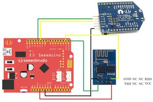
When we get the esp-f module, we can test it according to the following wiring:
That is, VCC, EN connected to 3.3V, gpio15 GND grounded, TX of the module, RX connected to the serial port tool, Rx, TX, RST pin low level reset, unnecessary IO pin can be suspended, if you want to download the firmware in the module, please pull down gpio0 (warm tip: if you buy esp-01s / M / F1 / F2, you only need to connect to VCC GND RX TX to work normally). If you purchase esp-01 module, you only need to connect ch-pd to VCC. Others can be connected according to the following figure (no IO port can be disconnected).
The wiring is as follows:

figure1.1
2.Test
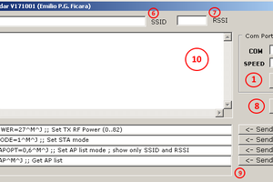
After the wiring is completed according to figure 1.1, please check the circuit in detail and confirm that there is no problem. Please open the serial port debugging assistant and select the corresponding COM port. The configuration mode is baud rate: 115200, data bit: 8 parity bit: none, stop bit: 1 flow control: None
The configuration information is as follows:
To confirm that there is no problem, please press the K1 key RST reset key (low level around 300m), and the print information is as follows:
Display "ready" to prove that the startup is normal.

common problem:
1. The key does not reflect
(1) please check whether the power supply of the module is 3.3v/800ma;
(2) please check whether TX and Rx are connected in the wrong position;
(3) check whether the port number is selected correctly and whether the port of serial port debugging assistant is closed.
2. The keys are all disorderly
(1) please confirm the baud rate of the module with the module manufacturer;
(2) please check whether the USB to TTL for communication with the module is compatible. It is recommended to use the USB to TTL made by chip ch340 and CP2102
(3) please confirm whether there is a problem with the program in the module.
3.Burning program
Open ESPFlashDownloadTool_v3.4.1 download tool, and select the corresponding chip model

4.Instructions
- Open the serial port debugging assistant to power on the module and print the information as follows:

Remember to send a new line when sending a command
Send “help” to view the command format,
Send “set ssid 1234”
Send “set password 123456789” // connect WiFi of router
Send “save” / save
Send “set ap_ssid 123010” // set the WiFi name of esp8266
Send ”set ap_password 9876543” // set the password of esp8266
Send “save” // save
Send “show” // to query the settings
Power on and restart OK

Firmware download link:
 Emilio P.G. Ficara
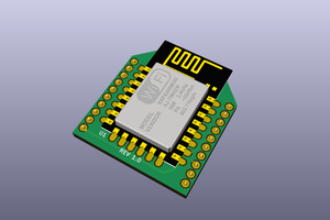
 Clint Stevenson
 Rand Druid