0%
0%
Light Sensor switch using raspberry pi zero
using a raspberry pi zero w and a light sensor module from Adafruit, I made a light sensor that controls a few smart plugs in my house
 Remi Martel
Become a Hackaday.io member
Already have an account? Log in.
Just one more thing
To make the experience fit your profile, pick a username and tell us what interests you.
Pick an awesome username
hackaday.io/
Your profile's URL: hackaday.io/username. Max 25 alphanumeric characters.
Pick a few interests
Projects that share your interests
People that share your interests

 Ian Maday
 Brenda Armour
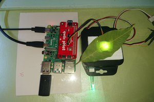
 Guillermo Perez Guillen
 Bikash Narayan Panda