 iliasam
Open Hardware scanning laser rangefinder based on Time-of-Flight principle.
There is a big article in Russian about this project: https://habr.com/ru/post/485574/
Google translation: https://translate.google.com/translate?hl=en&sl=auto&tl=en&u=https%3A%2F%2Fhabr.com%2Fru%2Fpost%2F485574%2F
The characteristics of this LIDAR are:
Scanning speed: 15 rotations/s.
Measurements frequency: 10 kHz.
Angular resolution: 0.5 deg.
Scanning angular range: ~230 deg (defined by mechanics).
Power: 0.1A at 5V, start current is 0.8A.
Minimal distance: 5 cm
Resolution: depends on distance and surface type. For example, at light-gray wall:
Distance 10m: -> Max distance values scattering = 3 cm (0.3%)
Distance 20m: -> Max distance values scattering = 13 cm (0.6%)
Distance 25m: -> Max distance values scattering = 17 cm (0.8%)
Distance 30m: -> Max distance values scattering = 30 cm (1%)
Size: 50x50x120 mm
Price of the components of this LIDAR is ~114$ (without delivery).
Structure schematic of this LIDAR:
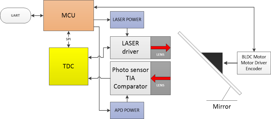
This LIDAR consists of those parts:
Photodiode circuit. Contains: APD (Avalanche Photodiode), boost converter for it, TIA (transimpedance amplifier).
First PCB version was based at AD500-8 APD, second version is based at MTAPD-07-13.
APD need high DC voltage (90-130V) to for its internal gain, so the is a step-up converter for generating this voltage. It is controlled by MCU.
Signal amplification is made by MAX3658 TIA.
Laser circuit. Contains: Laser diode, Short pulse circuit, MOSFET driver, current sensor, bust converter.
I'm using SPL PL90_3 laser diode. It is generating ~50 Watt light pulses with ~20ns duration.
Short current pulses for the laser diode are produced by short pulse circuit, based at high-speed MOSFET (BSZ165N04NS G). This MOSFET is controlled by special driver UCC27511DBVR.
Laser current is monitored by current sensing resistor. Signal from it is digitized by fast comparator. This digital signal from the laser is used as a START signal for the TDC.
Time of Flight measurement circuit. Contains: TDC, fast compactor.
I'm using TDC-GP21 TDC (Time-to-digital converter IC) for measuring Time-of-Flight of the the light pulse. This chip is defined for ultrasonic flow meters, but it also could be used in laser rangefinder. It is capable to measure time intervals with ~90 ps resolution. This corresponds to ~13mm of measured distance.
Fast comparator is needed to convert signal from TIA to a digital form. Threshold of this comparator could be set by MCU. Digital signal is used as a STOP signal for the TDC.
This TDC could detet both rise and fall events at its STOP input. It is used in this project for measuring received pulse duration.
MCU for LIDAR controlling.
I'm using STM32F303CBT6 MCU.
BLDC motor and it's driver. Also there is an optical encoder at the motor's shaft.
BLDC motor is used for rotating scanning mirror - they are directly connected together.
Scanning mirror.
I'm using octagonal mirror with first surface coating as a scanning mirror. Link to its manufacturer is given at "LidarTotalBOM.xlsx". Its drawing is given here: https://github.com/iliasam/OpenTOFLidar/tree/develop/Mechanical/Mirror
Optics. Photodiode lens (CS-mount) and laser lens (M12 mount).
See Github for more details.
Video about this LIDAR:
 Andrew Ferguson
 Alan Green
 Hexastorm
 Sky Carter