Here is what you'll need:
1. an Apple iPhone/iPad
2. a (free or paid) account with Pushbullet
4. an ESP32 DevKit board which you can get in North America from Amazon or from China from AliExpress (30 pin with soldered header pins recommended)
5. a set of Max7219 display modules (I used 2 x 8-in-1 modules) from AliExpress in my final build (less soldering)
5. this open source Arduino code sketch
which uses other libraries (with due credit given in the comments of the code itself)
6. a momentary switch
7. a 10K resistor
8. an enclosure of some sort - more information below
9. a red acrylic cover to go with the enclosure (which is hard to find, but I got one locally from a plastic's shop) more info below
.
Here is how you set it up (this is at the 100 foot level, I'm not going to go into great detail - you're smart and can figure it out):
1. Sign on to your iPhone/iPhone
2. Open the Apple Shortcuts application; one way to do this is to say "Hey Siri, open shortcuts"
3. A screen should appear, tap on the "+" beside the 'Select' at the top of the screen
4. While perhaps not obvious, the screen will be waiting for you to enter a name for your shortcut, enter "Leave a message" (without the quotes) for the name of the shortcut
5. In search box, search for and add "Dictate Text"
6. In the search box search for and add "Get contents of"
7. For the url of the Get contents of, use:
https://api.pushbullet.com/v2/
Under Headers add:
Access-Token your Pushbullet Access Token from Pushbullet.com - Settings - Access Tokens
Under Request Body add:
type note
title Leave a message
body Dictated text
Notes:
A. Dictated text is a 'Magic Variable' in the Apple Shortcuts app - do not type Dictated text, rather select it in the Apple shortcuts app.
B. the words type, note, title and body should not be capitalized
8 . Tap on 'Done'
9. (optional) Press and hold on the shortcut, a window should open, press "Details", and then press the option 'Add to Home Screen"
10. Update the Arduino code to include your PushBullet Access Token (found on your Pushbullet Settings window),
and your WiFi credentials
11. Update the ESP32 board with the updated Arduino code
12. Assemble the case and plug in the ESP32
To make it work:
Give it a try by saying "Hey Siri Leave a message"
pause speaking until you hear Siri say "What's the text"
say (for example) "Hello world", or anything else you may like.
.
Here are some things which I learned along the way:
i) the enclosure listed above did not have a way to get the power cable in the back, so I remixed it to add one and to use a project box power coupler solution (also listed above) - but you could drill a hole too - ultimately I designed my own enclosure - files available on github (below)
ii) when first powered up for some reason all the Max7219 modules didn't light up, but if I just unplugged it and plugged it in again it worked
iii) a free Pushbullet account expires after 30 days of inactivity; special code in the sketch above prevents that
v) the more Max7219 modules used the more power it takes. Originally, I used 3 x 4-in-1 modules (i.e. 12 individual modules) don't know how many, if any more, you can add and still power via a usb wall jack. Later I changed this to the equivalent of 16 modules, and it continues to work fine. I am using a power adapter that has 5v 4A, pugged into the ESP32's micro port.
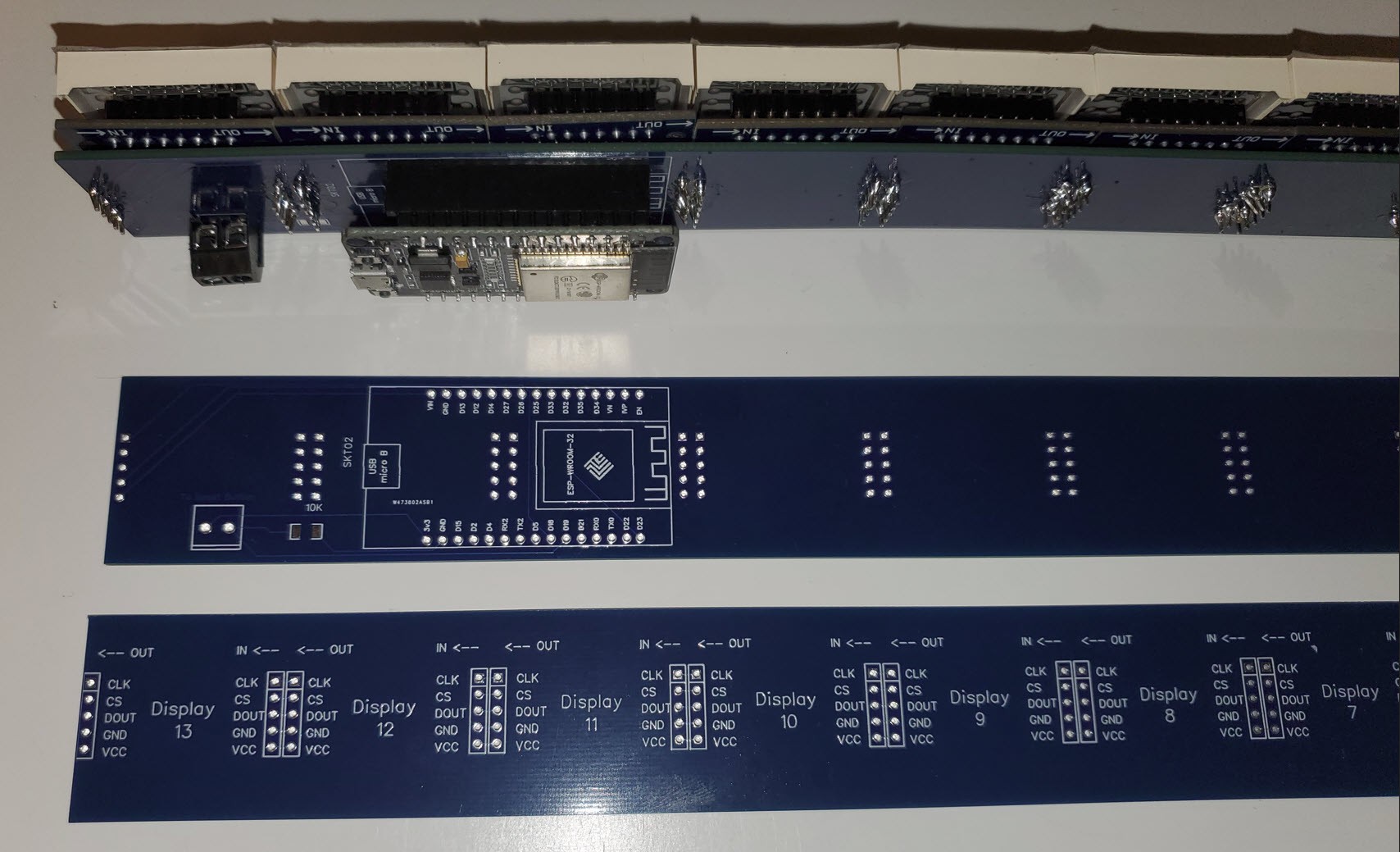
vi) later I designed a PCB board with the goal of reducing the wiring and making the connecting of the Max7219 modules much easier. Thanks to the leading PCB manufacturer PCBWAY I've managed to get some PCBs manufactured (in fact, after seeing this project on Hackaday, PCBWay reached out to me and sponsored this). The super news was that PCBWay did a fantastic job of building my board to my exacting specifications, the less-than-super news was that my exacting specifications were not very good; I had designed the board with the adjoining slots for the Max7219 modules too close together and some potentially to close to the header pins for the ESP32. This made fitting and soldering much harder and ultimately I ended up with a non-functioning prototype.
Also, I built the board assuming I would use individual Max7219 modules. This resulted in a lot more soldering than was needed.
I have since redesign it (version 2) to use two 8-in-1 Max7219 modules (for a total of 16 Max7219 modules) in the design as opposed to 13 individual Max7219 modules (version 1) - this reduced the number of needed Max7219 related soldering connections by 200 and gave me three more display modules.
Here is the version 1 attempt (which didn't work out so well) ... see version 2 further below ...
Close-up view of PCB board (the first is soldered with components, the next two are the two sides of the board without components):
Wide view shot of PCB board (the first is soldered with components, the next two are the two sides of the board without components):
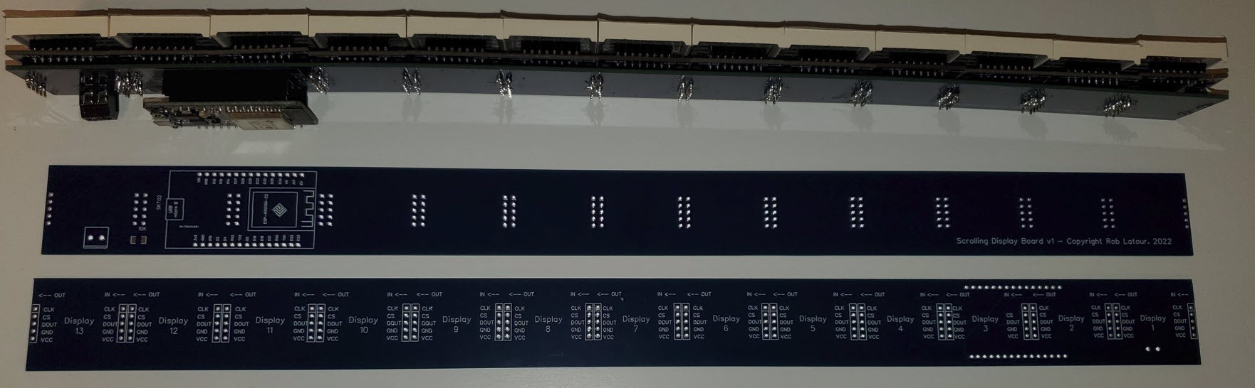
Here is the version 2 attempt which worked out much better and is something I am now quite happy with:
Improvements over version 1 as follows:
- used two 8 module Max7219 boards, rather than using a whole bunch of single module boards - this cut down on the soldering quite a bit
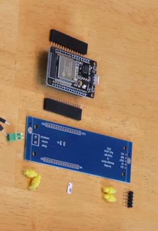
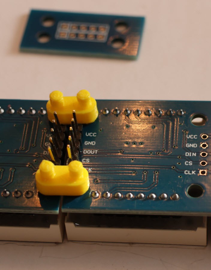
- made two PCB boards; one to hold the esp32 and the other to simply help join the Max7219 boards; this allows me to connect the modules much more easily.
- created 3D printed separators to help join the Max7219 boards, as well as to mount the esp32 PCB board to (the underside of ) one of the 8 module Max7219 boards
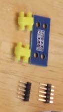
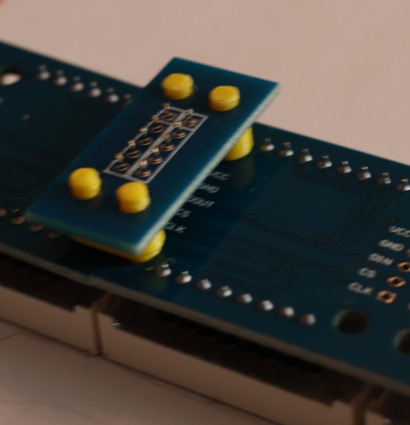
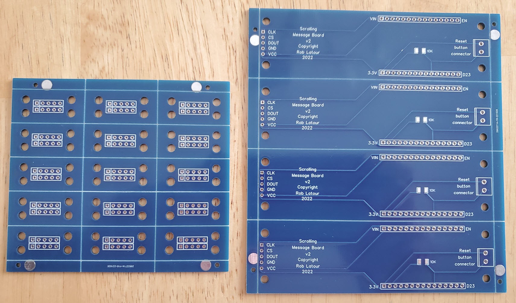
Here is the PCB board and separators which mount the ESP32 and join it to the underside of the 8 module Max71219 board:
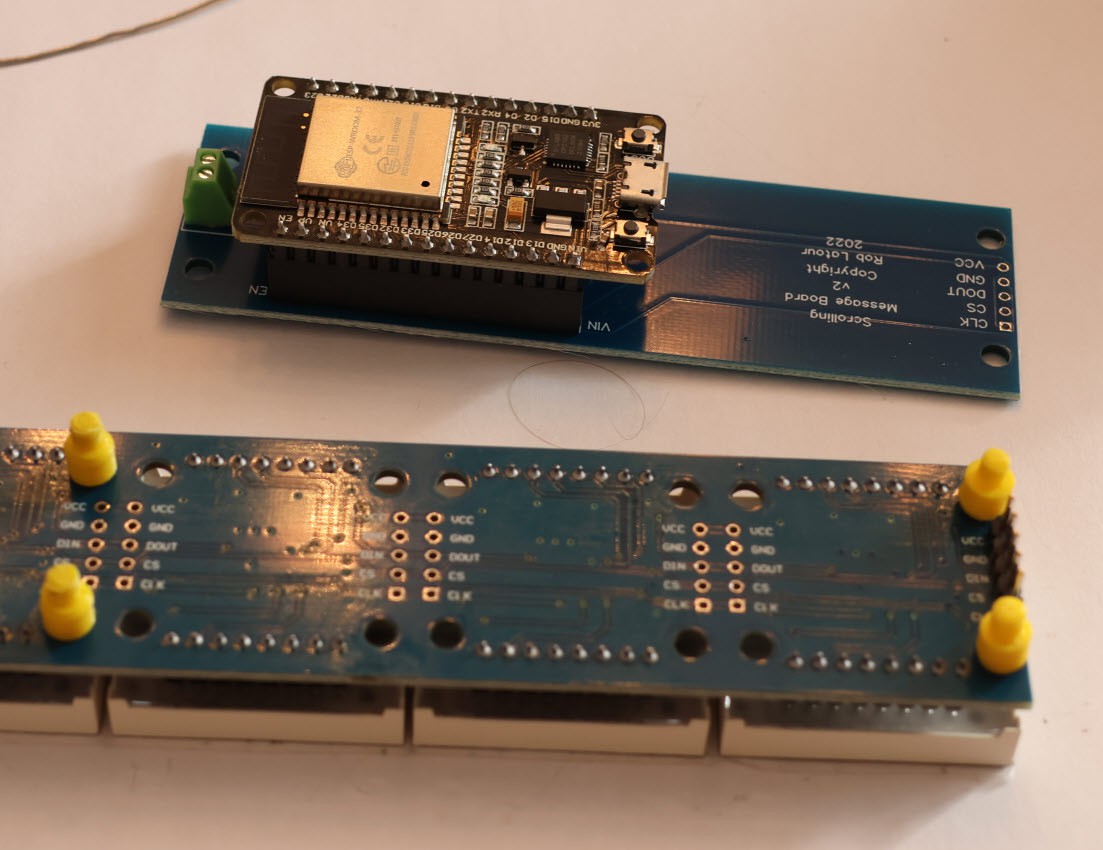
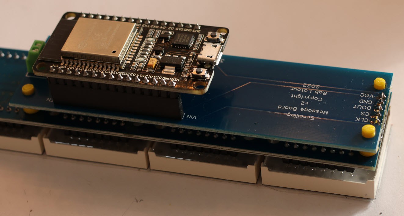
Here is the board and separators which help join the 8 module Max7219 boards:
I panelized both PCB boards, so when I ordered the minimum quantity of five of them (I used JCLPCB the second time) I effectively ended up with 20 boards to mount the ESP32 on, and 75 Max7219 joiner boards.
Here also, is a photo of all the parts, include the 3D printed case.
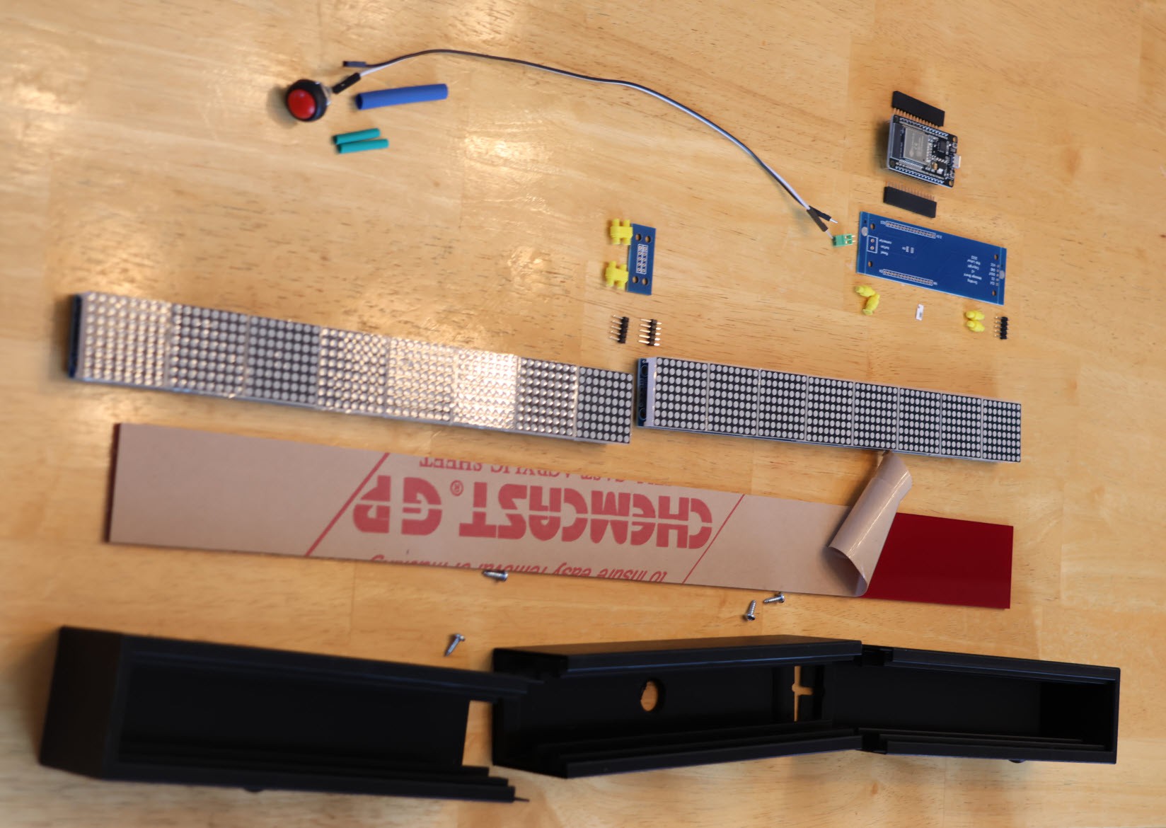
The 3D printer files for the case, which I pain shakenly designed, for a 16 (2x8) module Max7219 scrolling message board are linked to below - under the Open source links.
The red acrylic plastic I sourced from a local plastics store ( http://canusplastics.com/ ); they said they are happy to take small orders.
It is 1/8" thick, cut to 45mm x 533mm to fit exactly in my 16 module 3D printed case.
The four screws are #4 3/8" wood/metal screws; these I painted black to better match the case.
.
Open source links:
Software https://github.com/roblatour/esp32max7219
3D print files for the 13 and 16 module case builds + separators for use with the PCB boards : also in the GitHub above
PCBs, designed with EasyEDA (free) standard: https://oshwlab.com/roblatour/pcb_scrolling-message-board-v2
.
Bonus:
Finally, for reading this far, if you want to control your (Windows) computer with your Google assistant, please check out a freeware program I wrote called Push2Run