The goal of this task is to develop a solution to implement the neural network nodes using discrete components.
Initial idea
The initial idea was to use analog multipliers based on a SE discussion. The source also references an additional solution using a MOSFET, but I couldn't find a way to implement this. The other solutions were an AD633 analog multiplier and the MPY534, the latter a bit more expensive.
Either way, both solutions theoretically could work, nevertheless, it could get expensive quite fast. A quick back of an envelope calculation is, I'd need 10 nodes, with 16 multiplications and additions, then I'd end up needing 160 multipliers. The cheapest is the AD633, and it goes for around 10€ a piece. For 160, they come down to around 7€ each, or 420 € just on multipliers. That's a hard sell.
There was another solution mentioned using log-add-antilog OpAmp circuits. These would need also log amplifiers, and it becomes very expensive very quickly as well. In the end, the easiest to implement, and cheapest, was the analog multipliers.
All in all, this seems like a dead end, not even taking into account the fact that I have negative numbers to multiply. Maybe this is also possible with analog signals, but I cannot wrap my head around it.
I got it all wrong
It occurred to me that if this is so simple to implement, then someone must have done it before. So I started to do some research and got some papers from the 80s where people where designing VLSI chips to deal with neural networks. So, I cannot do VLSI, what else have you got?
More recently, the work from wolfgangouille stands out with the very cool implementation of neurons in his very cool Neurino project.
A bit more search got me to memristor bars from the nice video of Mr. Balasubramonian explaining his implementation. Now, memristor bars are really cool from the point of view of implementation, you've got voltage signals coming in, a bunch of resistors and conductors and finally a current output that should be transformed onto digital signal or voltage if needed. Hey, this is great!
Not so fast, we still have to deal with the negative values on the weights.
Some of the weighs that came with the model were negative. Now, memristors work by turning the input signal (a voltage) onto a current by passing through a resistor. The resulting current is the product of the voltage by the conductance of the resistor. So how on earth am I going to come up with a negative conductance resistor? Well, since I'm not EE trained, I didn't really know this was possible but Wikipedia proved me wrong.
Even though there are some conditions in which some semiconductors seem to show this behaviour, it didn't seem like an easy thing to throw in my NN. We needed a different solution.
Turning the problem upside down, I tried to reflect on what had to take place in my model circuit.
Case 1. Positive weight
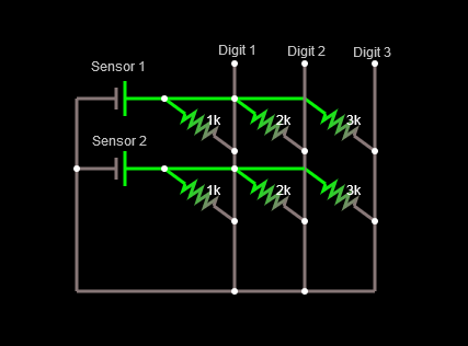
In this case, the weight would be represented by a resistor, the voltage multiplied by the conductance would render a current. The current would be added to the current coming on the Digit 1 wire and would be transformed onto a signal at the exit.
Case 2. Negative weight
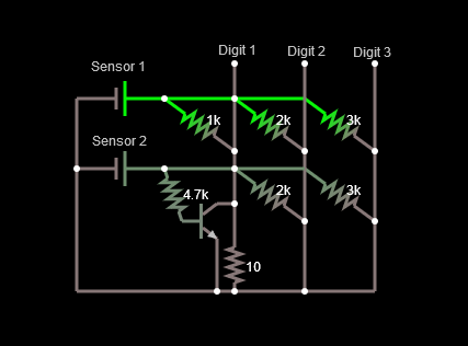
In this case, instead of putting current into my wire, I'd need to substract the current from the wire. So, I just need to find a solution to remove current from the wire, right. Well, put like that it's more or less easy. The problem might be finding a linear way to do this, but a simple implementation can be found below. The negative weight is represented by a transistor driven by the current created by the voltage coming from the sensor and a resistor. As the transistor gets current across the base, it allows some of the current traveling through the wire to escape. Hence, the actual current in the Digit 1 ampmeter goes down as the voltage from the sensor increases.
Below is a short video of the memristor with the negative weight in action.
As the Sensor 1 voltage changes, all the outputs on Digits 1 to 3 increase as the currents are all produced with positive weigths.
As the voltage on Sensor 2 changes, the current signal for Digits 2 and 3 increases, whereas the current for Digit 1 decreases, reflecting a negative weight node.
The math need some attention since this is just a proof of concept. In order to get a proper signal treatment, proper choice of transistor and resistors will weigh on the accuracy of the results.
Signal constraints
We have solved the issues pertaining the design of the nodes of the neural network. Nonetheless, there is still another issue. The signal from the photoresistor is not linear as can be seen from the plot below.
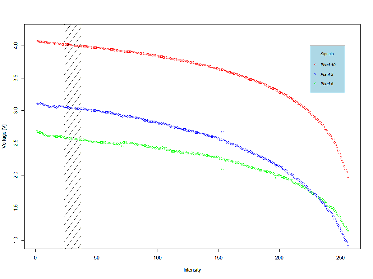 There is two ways to work with LDRs as sensors. The first one is to work only in the linear regions, but then we'd need to make sure all the sensors have the same response which would allow a good quality signal. From my limited experience with LDRs, this can be tricky and I've found a lot of inconsistency in consecutive readouts. The second one is to work with binary signals, i.e. instead of reading out an intensity from the pixels, round the intensity values and read out 0s or 1s.
From the work carried out in the development of the decision trees, binary signals are much easier to read an manage when using LDRs. Nevertheless, a lot of information is lost and success using binary signals could be obtained only by using a bigger matrix.
An example of a digit "5" with a binary 4x4 matrix versus a 7x7 matrix is depicted below. As can be seen, too much information is lost in the 4x4 matrix.
 | 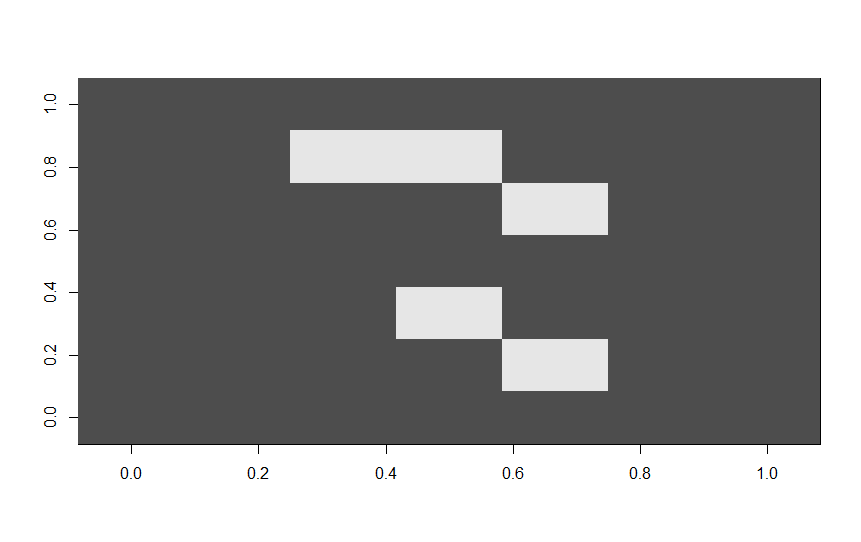 |
With a 7x7 binary matrix training a neural network using 1000 numbers, the model below is obtained with an acceptable accuracy.
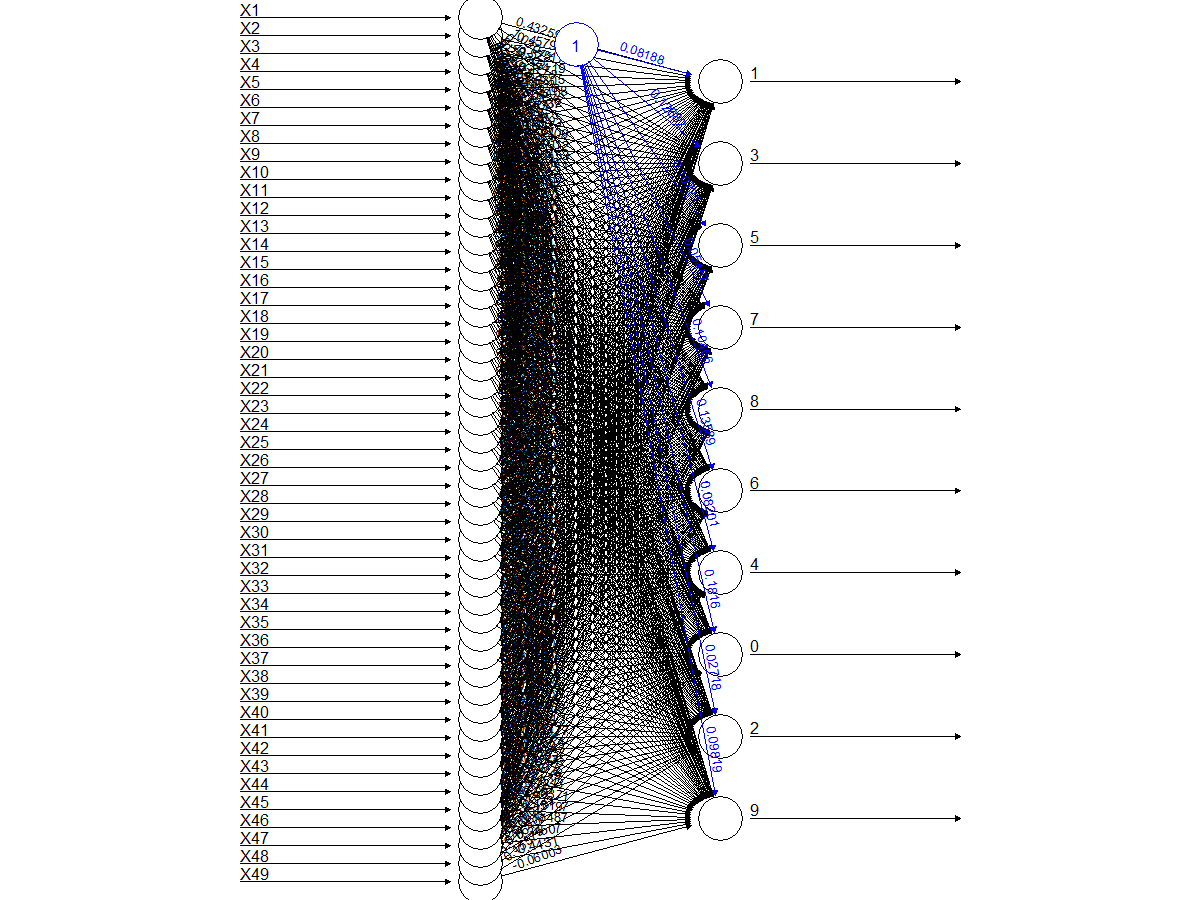
The accuracy for each digit using the binary 7x7 matrix is as follows:
        0         1         2         3         4         5         6         7         8         9
0.6105130 0.4642998 0.3916667 0.4367953 0.3751996 0.1865399 0.4743822 0.4334711 0.2476398 0.1370285
Conclusion
A binary solution seems to be the best solution as long as we're keeping with the LDRs. Photo-diodes seem to be an alternative but I'm only getting comfortable to work with voltage signals for the time being.
Next, design my first PCB to detect MNIST digits using a neural network.
Discussions
Become a Hackaday.io Member
Create an account to leave a comment. Already have an account? Log In.