 Martin
Ok, I explained the purpose of this project in the header, now lets get technical.
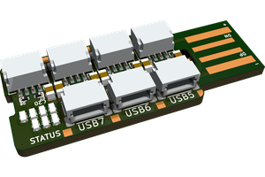
The four leftmost ports are compatible with QC3.0 (up to 24 W per port, 12 V 2 A), FCP (Huawei), DCP (Apple) and BCP (Battery Charging Protocol). They take +12 V from the PSU and step it down (if needed) using the 4 FR9885 buck converter ICs. It's basically my Quick Charge 3.0 board, just quadrupled. The IC taking care of all the protocols is the FP6601 (I got mine from LCSC).
The remaining six ports are connected to the +5 V from the PSU, so no buck conveter is needed. They are still equipped with the FP6601, just to enable the devices to draw up to 2 A from each port (otherwise, some would draw just 500 mA).
Lastly, there's one port connected to the +5 V stand-by line. This port can provide power even when the PSU is off, and it's again equpped with the FP6601 port controller.
The board also contains three dummy load resistors, on/off switch, two LEDs, screw terminals (providing 3.3 V, 5 V, 12 V) and a 6 pin header terminal, providing symmetrical supply (±5 V and ±12 V).
The entire board might look complicated, but that's because everything is there at least 4 times. It took me only about two hours to hand-assemble it. I also printed a simple bracket and mounted it to an old power supply I got from a Dell computer.
All the files (Eagle, gerbers, ...) are available on GitHub.


 rbtsco
 piat.jonathan
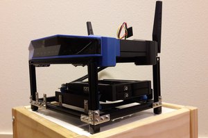
 Stanislas Bertrand
 Andrew
Nice project! Just wondering, what is the purpose of the load resistors?