 Ameer
AmeerAfter completing the mechanical assembly of the rover, a Raspberry Pi-4B computer and Several other components will be places on a panel inside the rover - ultimately connecting to the 10 Servo Motors that move the rover. It will be wirelessly controlled by a tablet that communicates with the rover over a local network using an on-board rechargeable router.
-
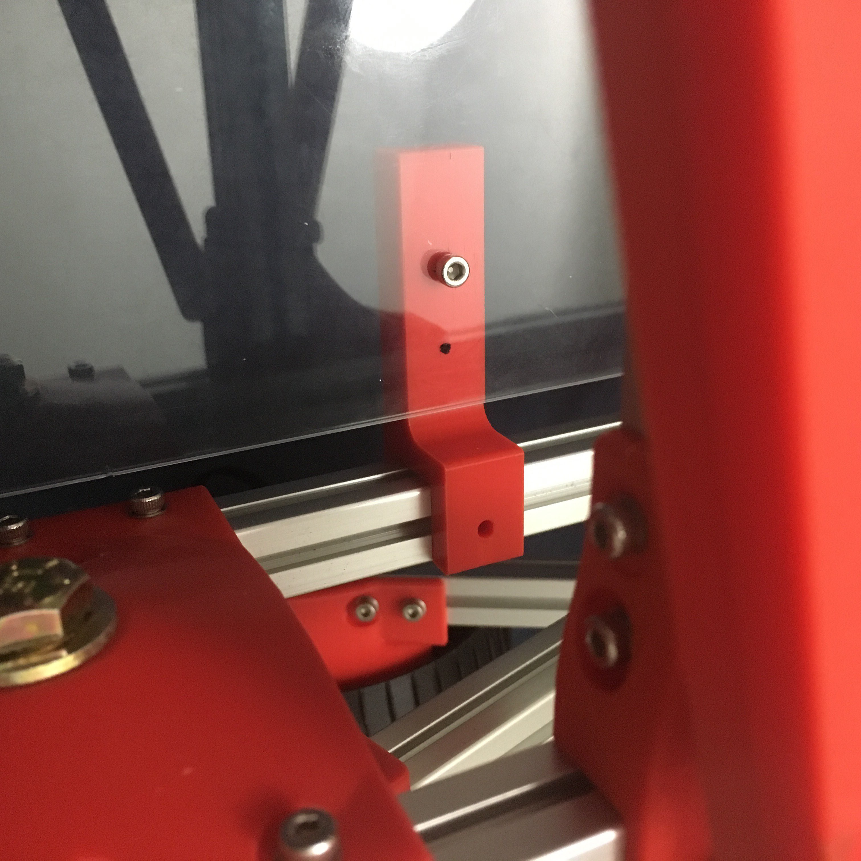
The Floor Panel I used for the rover is a 3mm thick clear plex glass piece.
Size is 40cm x 23.5cm so it Slides in from either front or back of Rover Chassis box and fits perfect inside the Aluminum Extrusion Grooves. I 3D printed 2 simple middle Floor Support Arms (shown in the pic below). I uploaded an stl. for them with the other files.
Here is a pic of the parts that will be within the rover's compartment, randomly placed on the floor panel:
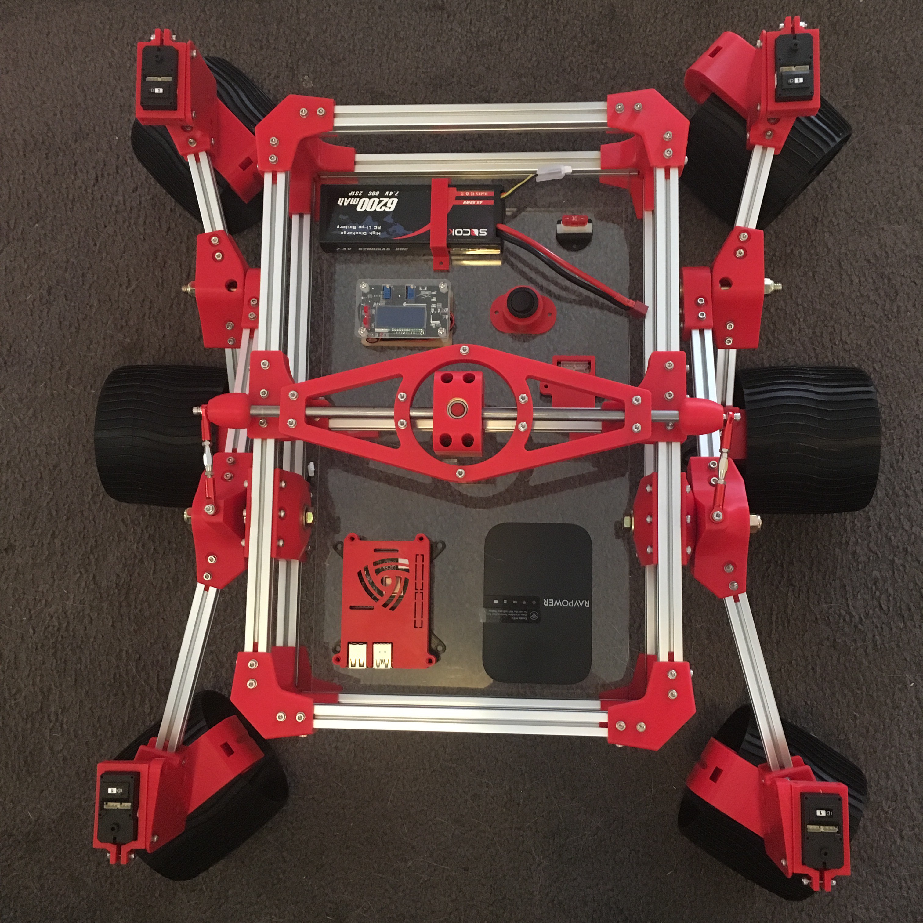
From top left: Battery, Fuse, Voltage Regulator, Power Button, Bus Linker, RPi-4B, and Router.
I 3D printed a Bus Linker Housing Bracket (in two parts) to mount it to the floor pan, and cover it, I added the stl.s to the other files.
-
Note: For the Li-Po battery, you should purchase Connector Wires, and a Wall Charger.
Discussions
Become a Hackaday.io Member
Create an account to leave a comment. Already have an account? Log In.