 M. Bindhammer
1. USB power supply and a reading light
USB power supply add-on gerber rendering:

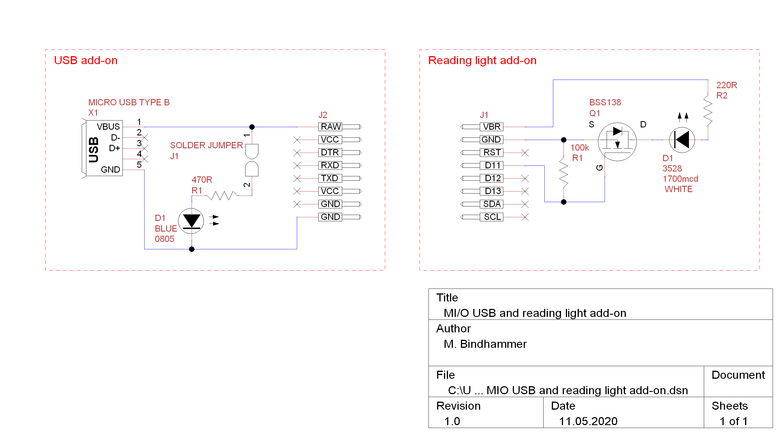
I added two additional solder pads (power isolation jumper) to enable the power indicator LED. Some may need it, some not.
Reading light add-on gerber rendering:

The LED (PLCC2 package) can be dimmed by PWM and controlled by the watch (e.g. switched on at 18:00 and switched off at 20:00).
Populated and tested add-ons:
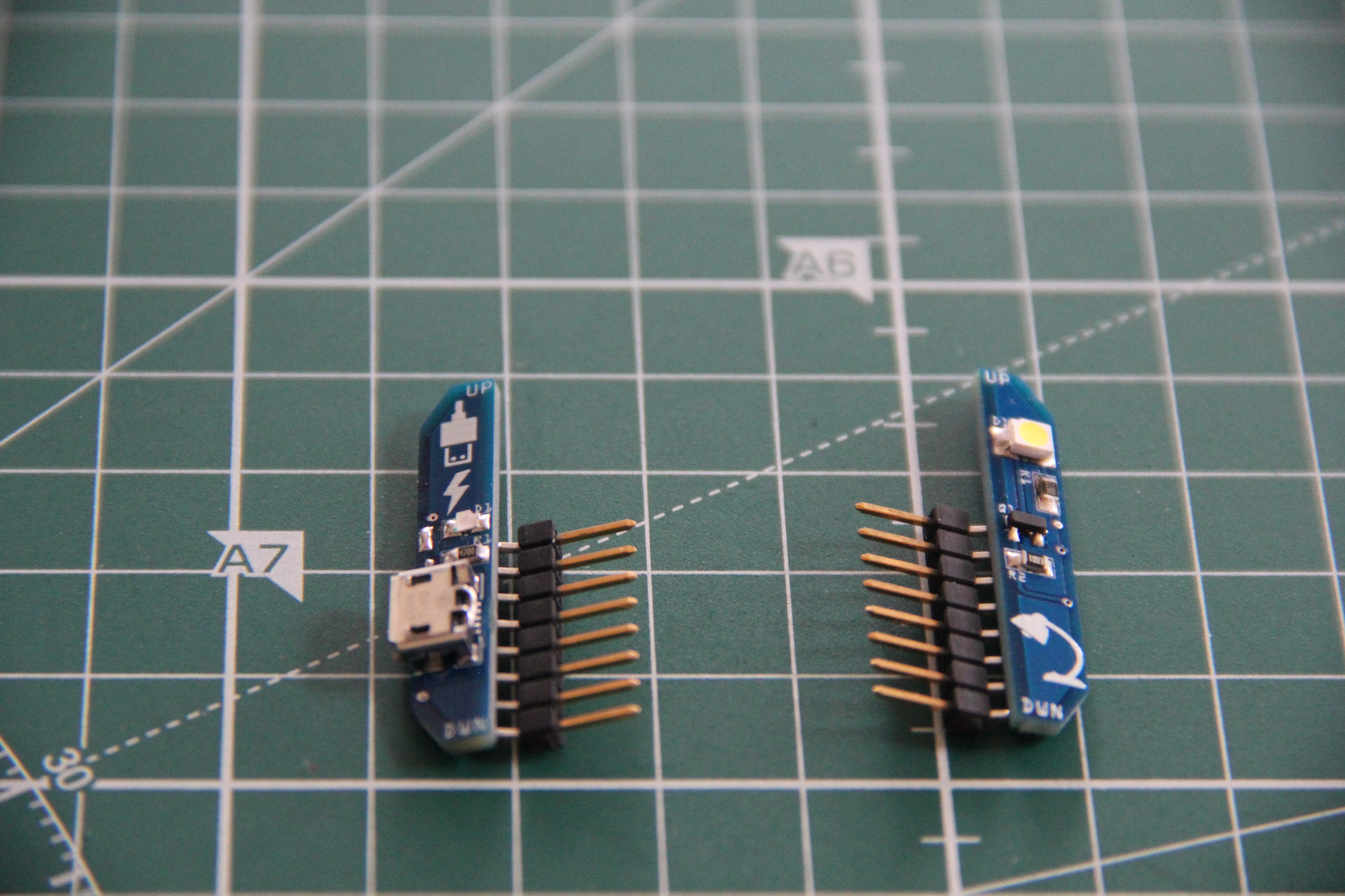
The connectors are male headers, 8-pin, SMD, 2.54mm, right angle.
Schematic:
2. FM radio
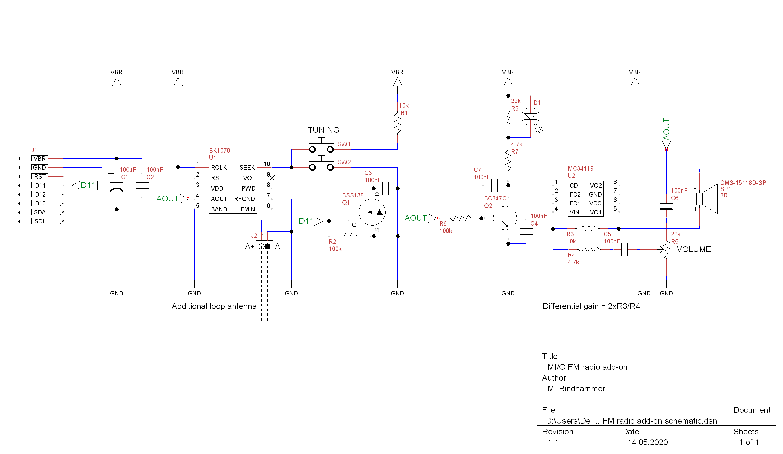
The FM radio is based on the receiver IC BK1079. The antenna signal is boosted in the analog part of the internal circuit by a highly sensitive amplifier (LNA, Low Noise Amplifier), whereas a regulated amplifier (PGA, Programmable Gain Amplifier) reduces the gain when the signal is too strong. The Analog-to-Digital Converter (ADC) converts the signal into a sequence of numbers, which is then processed digitally. The processing is done by a digital signal processor. It filters and demodulates the frequency-modulated signal and filters the audio signal so that only the audio frequency range is provided. It also controls the Automatic Gain Control (AGC) to prevent overmodulation. The processed signal is sent to the Digital-to-Analog Converter (DAC), which converts it into an audio signal. The finished radio signal is then available at the analog output AOUT. The digital tuning contains a microcontroller that controls the search and other functions. It uses a PLL (Phase Locked Loop) to precisely tune a high frequency oscillator that determines the receiving frequency. The PLL can be operated either digitally with a connected crystal (DPLL) or analog (APLL). An internal voltage regulator ensures a stable internal operating voltage even if the battery voltage is varying.
The complete schematic of the FM radio add-on is shown below. The audio signal is amplified by the low power audio amplifier MC34119. Volume is adjusted via the potentiometer R5, the radio can be tuned via the two tactile switches SW1 and SW2. When the gate of the n-channel MOSFET Q1 is put to a HIGH state, the MOSFET pulls the PWD pin of U1 to GND, and the BK1079 goes into power down mode. When the BK1079 is active, an average DC voltage appears at the analogue output (AOUT) together with the AF signal. This is used to switch the LED D1 on and to enable the amplifier U2 via the npn transistor Q2. In the power down state U1 switches this DC voltage off. The transistor Q2 turns off, the LED too and the amplifier is driven into power down state via its chip-disable input.
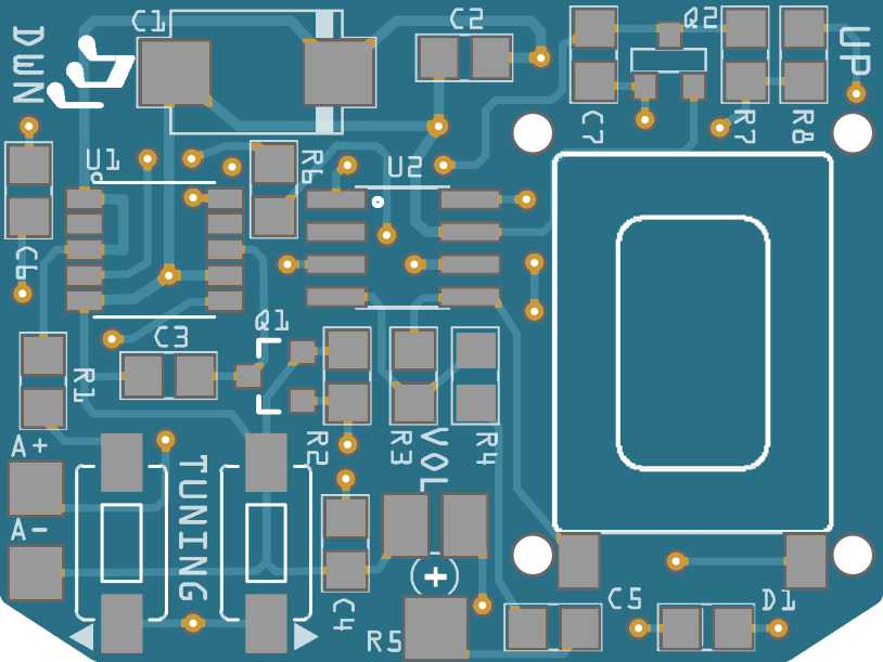
The SMD speaker is very small, just 11 x 15 x 3mm; I think it is used in smart phones. I put 4 holes around the land pattern of the speaker to have the possibility to mount a 3-D printed enclosure to improve the sound of the speaker if necessary.
3-D model of the speaker enclosure. As a reference I used Best Practices for Designing Micro Speaker Enclosures.
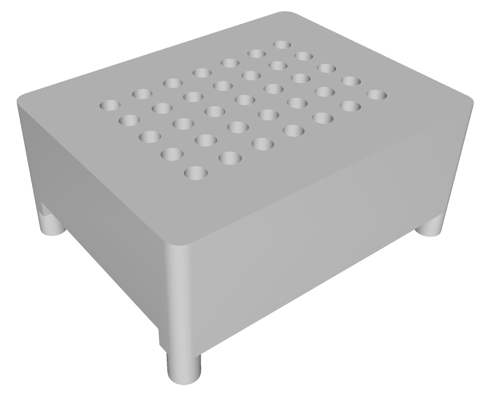
3-D printed speaker enclosure and speaker:
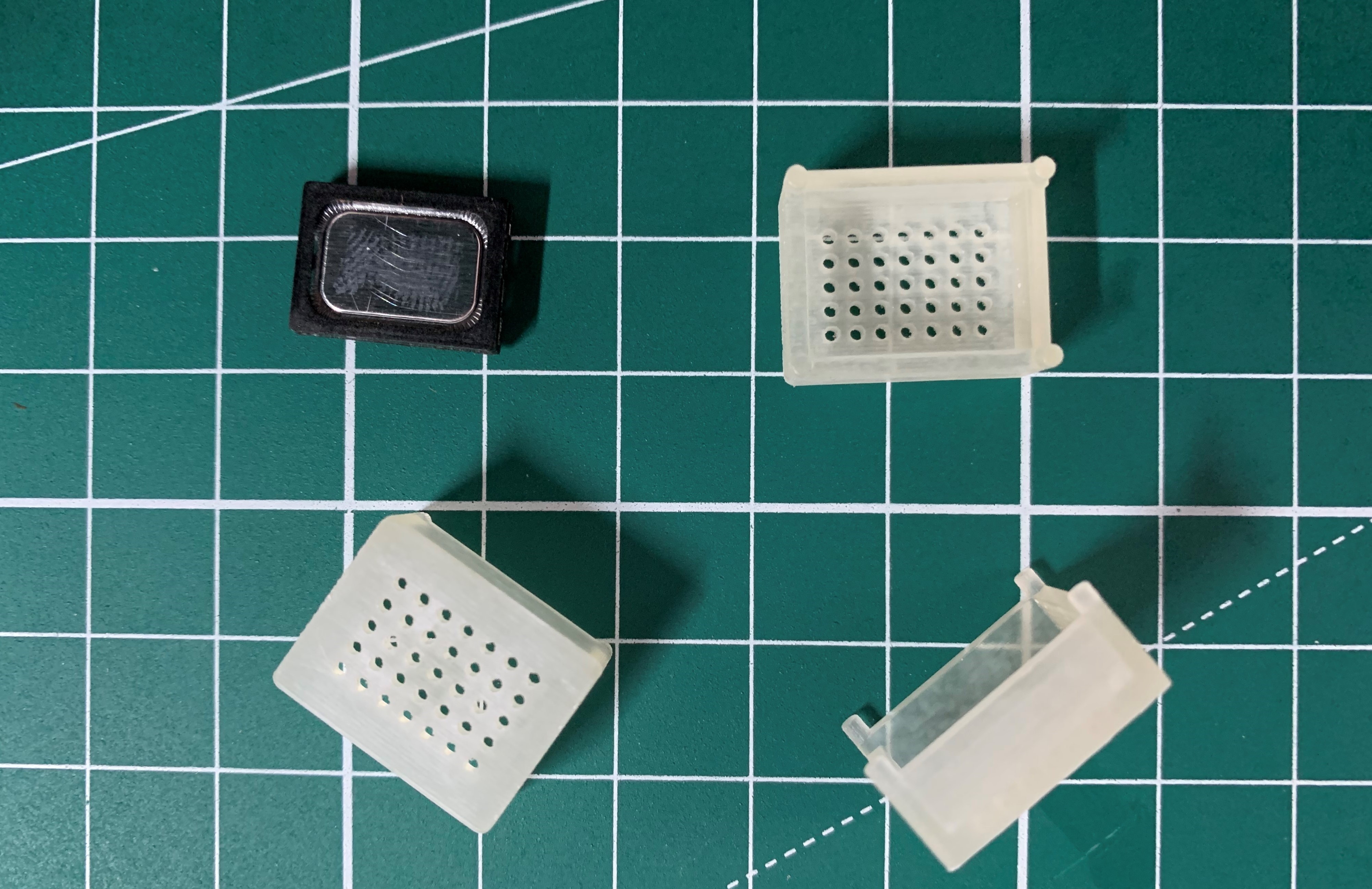
Enclosure was printed by Shapeways, using Fine Detail Plastic setting.
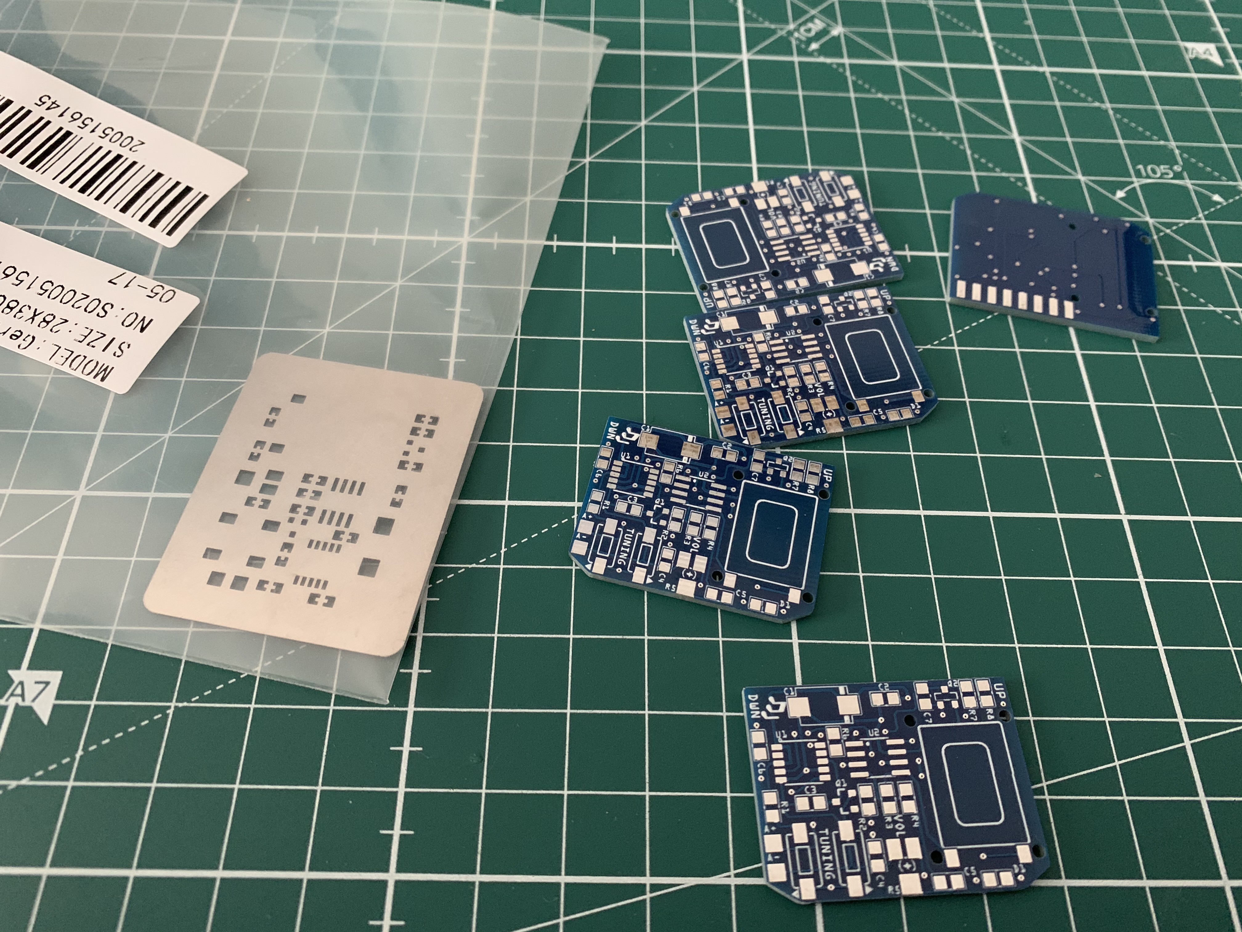
The standard 5 PCBs and custom cut stainless steel stencil from JLCPCB:
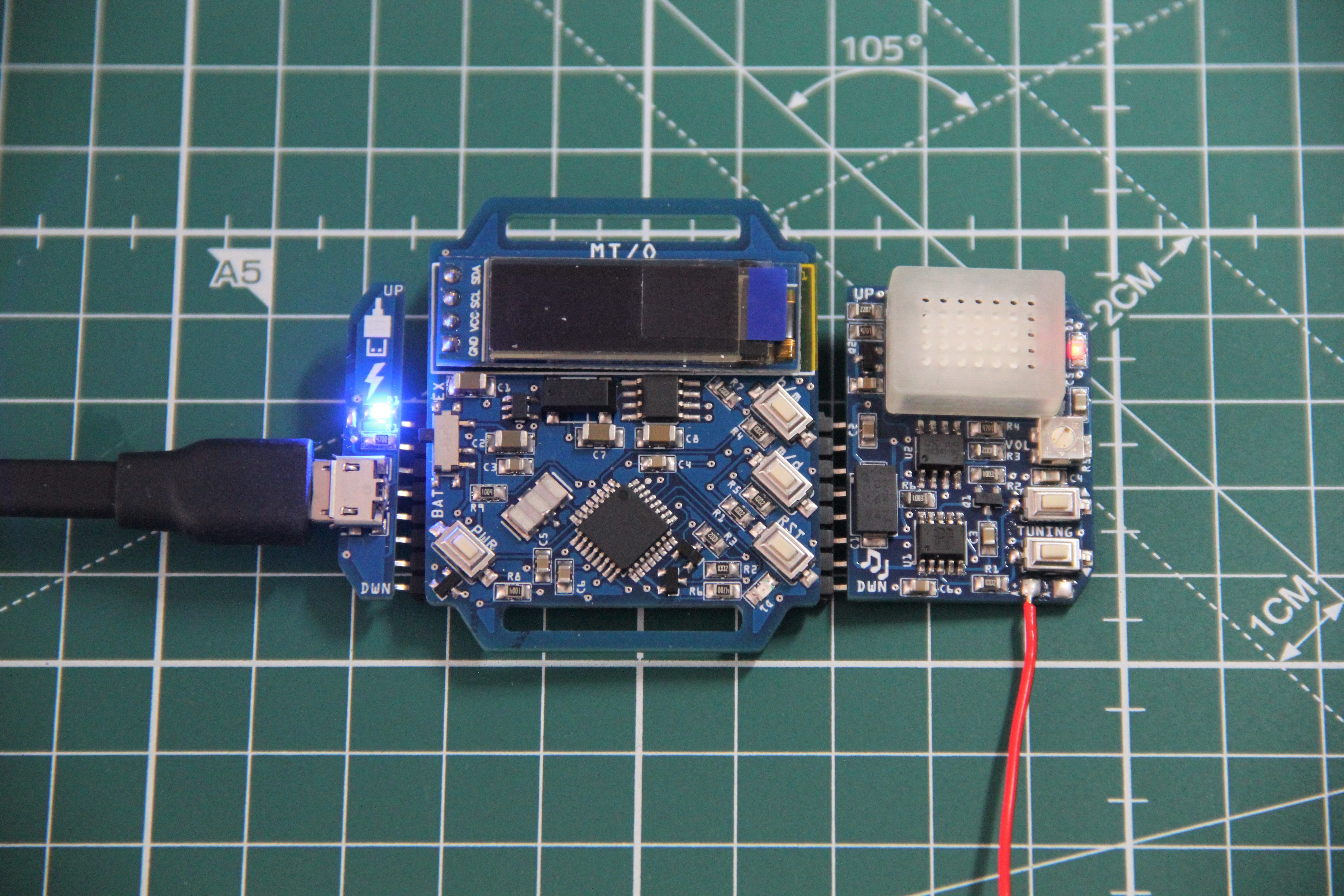
USB power supply, watch and finished FM radio add-on in use. An antenna with a length of 20 cm delivers crystal-clear reception.
3. Watering system for indoor plants
Capacitive soil moisture sensor gerber rendering:
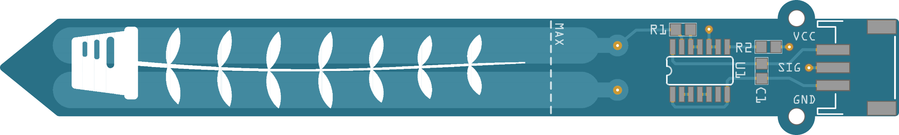
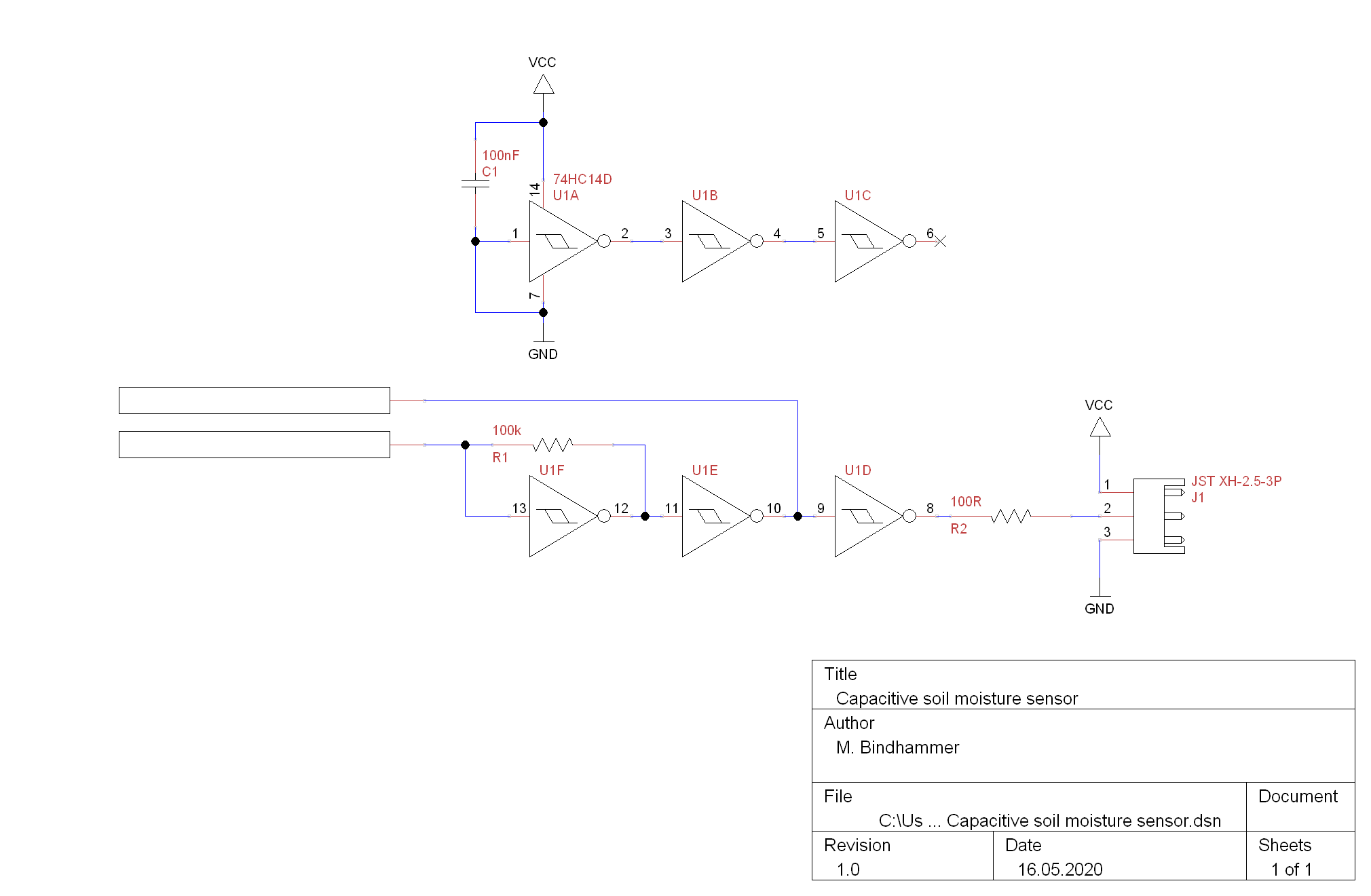
The sensor has two electrodes that form a plate capacitor. The soil surrounding the capacitor serves as dielectric and influences its capacity - the more humid the soil, the greater the capacity of the capacitor. The capacitor, a resistor that charges the capacitor and 3 inverting Schmitt triggers (one stage just acts as a buffer) form a simple oscillator whose frequency depends on the capacity of the capacitor. The frequency is approximately in the range of 40 to 400kHz and can be measured via pulseIn()command and analyzed by the microcontroller.
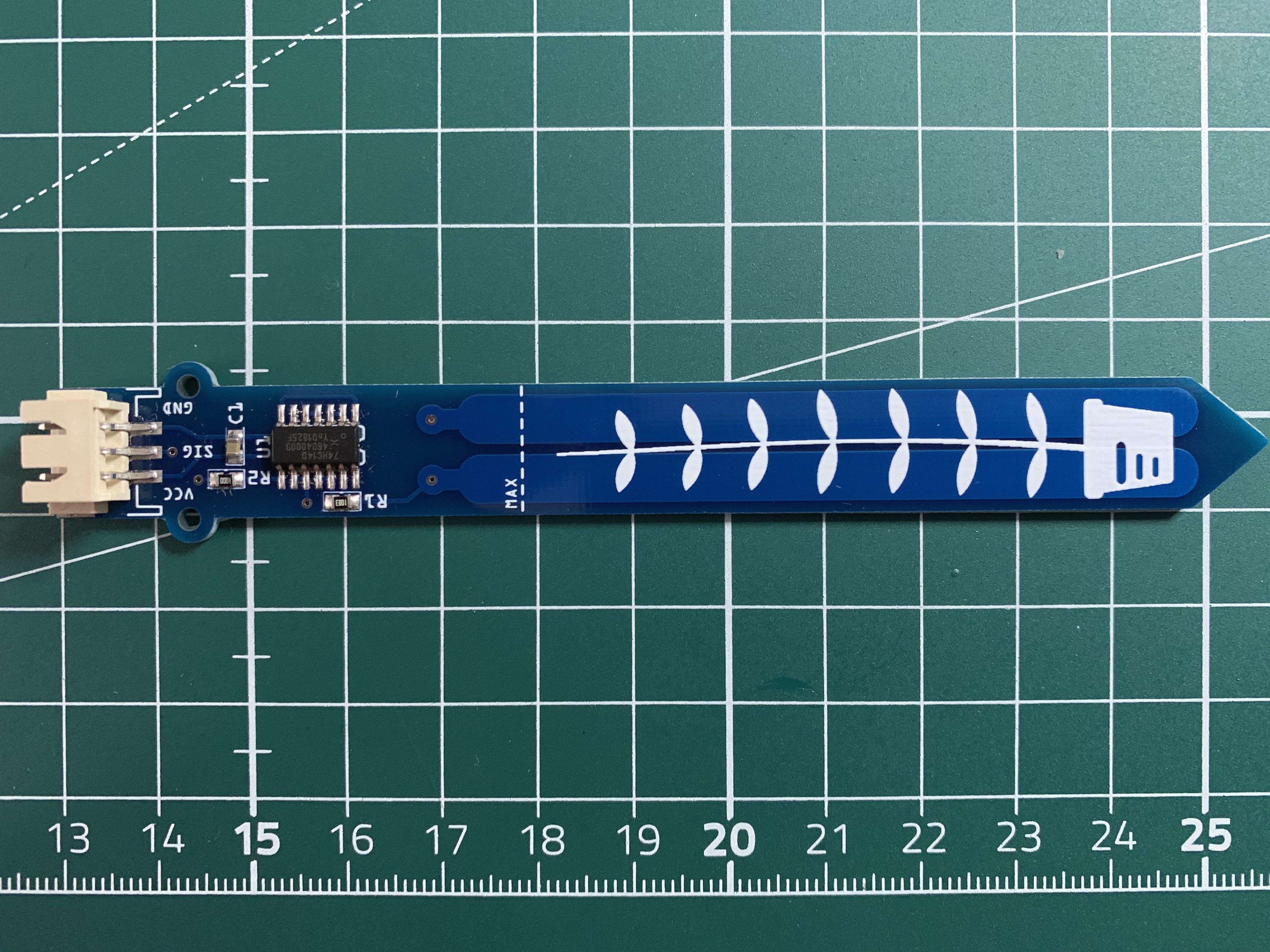
 Populated PCB:
 Test code for the soil moisture sensor:
int pulseIn_pin = 7;

void setup() {
  pinMode(pulseIn_pin, INPUT);
  Serial.begin(9600);
}

void loop() {
  unsigned long duration;
  duration = pulseIn(pulseIn_pin, HIGH);
  int moisture;
  if (duration > 27) duration = 27;
  moisture = map(duration, 0, 27, 0, 100);
  Serial.print("Soil moisture: ");
  Serial.print(moisture);
  Serial.println('%');
  delay(500);
}
While the soil moisture sensor is easy to manufacture, it is difficult to find a suitable micro water pump, if possible mountable on a PCB with the lowest possible power consumption, 3V operating voltage, self-priming, whether piezo, membrane, peristaltic or paddle wheel. These pumps are available in all these designs and requirements in the medical field, but they are very expensive and cannot be bought by private individuals. I have experimented in the past with piezo pumps from medical supplies for a medical related project, these pumps would be perfect, but it is disproportionate to water the indoor plant with a pump that costs $150 or more.
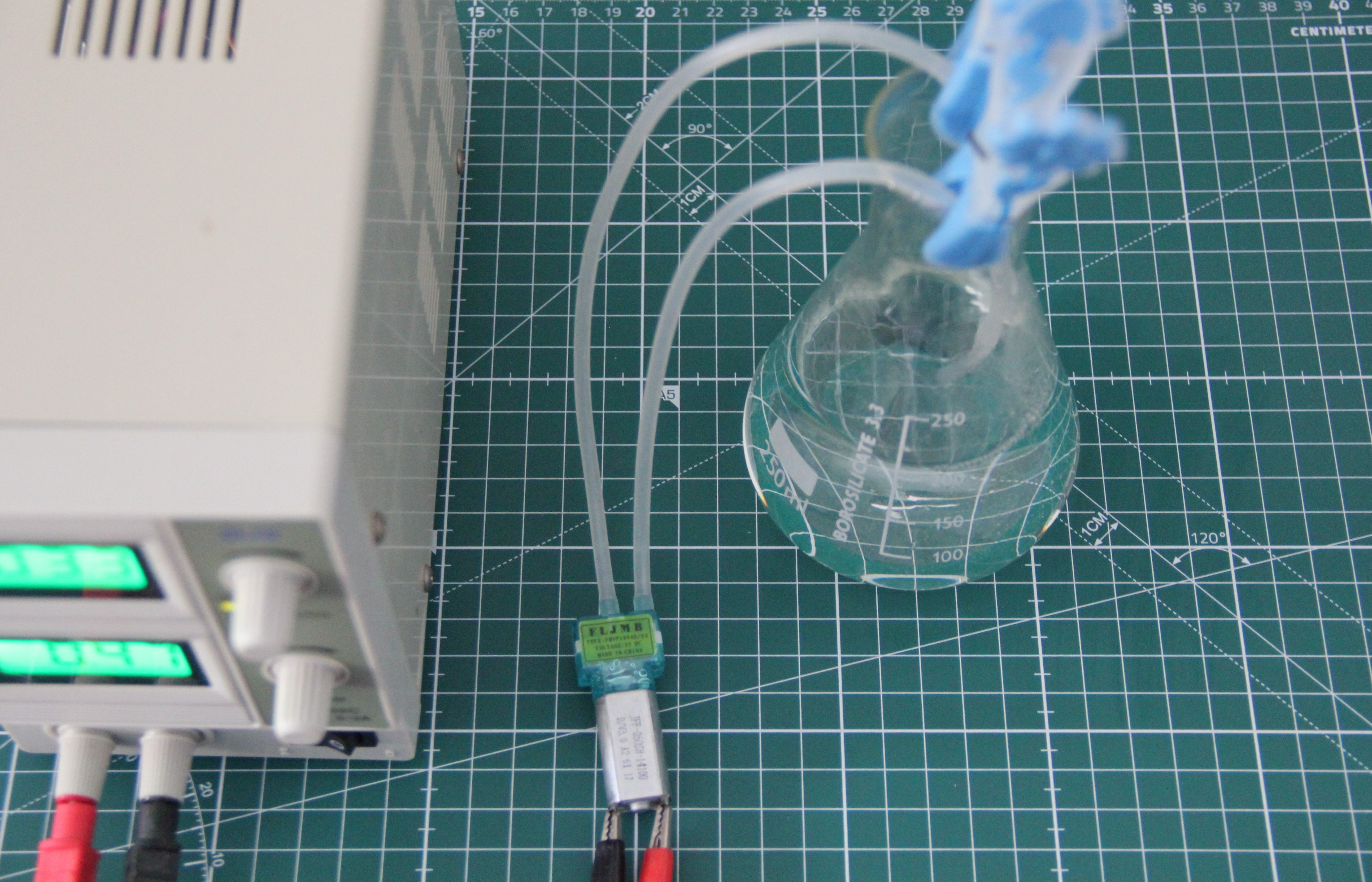
The other day I found these micro pumps on Ebay (FMVP1004B-03). They are actually intended for air (pumping up the cuff of blood pressure monitors), but the sparse data also suggested that they can be used to handle water as well. It works but unfortunately they leak after a few minutes.
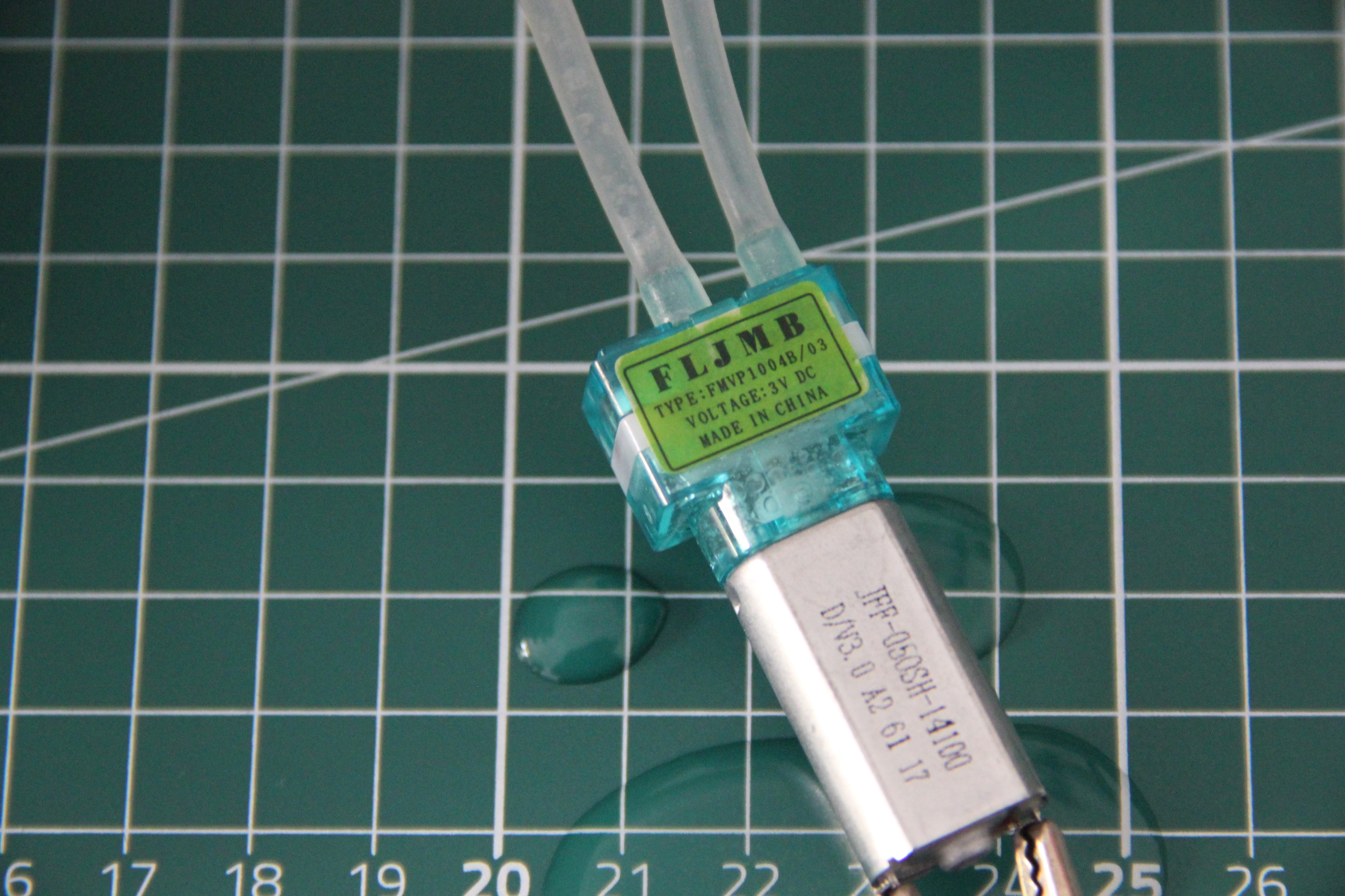
After disassembling the pump, the reason for the leakage became obvious.
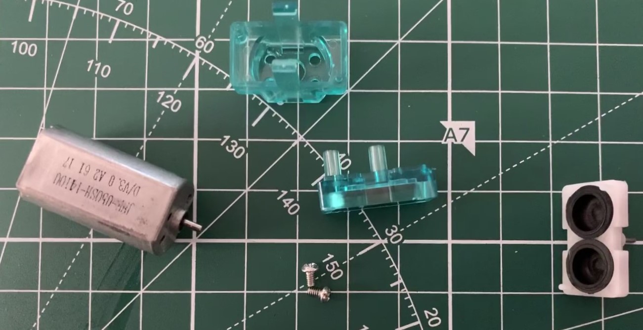
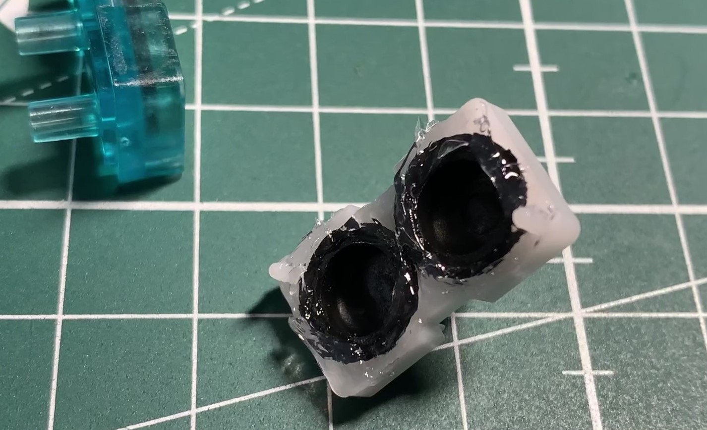
The two sealing surfaces of the rubber bellows are not pressed strongly enough against the counterpart, because the pump body is not screwed together, it is only held together by two clamps. The two sealing surfaces of the rubber bellows were coated with silicone and the pump body was reassembled. Excess silicone was removed. After curing the pump can be tested again.
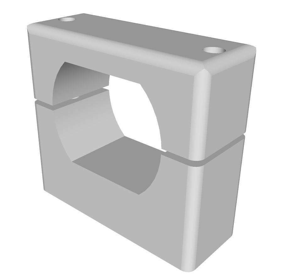
In the meantime, a 3-model of the pump's mounting on the circuit board has already been made:
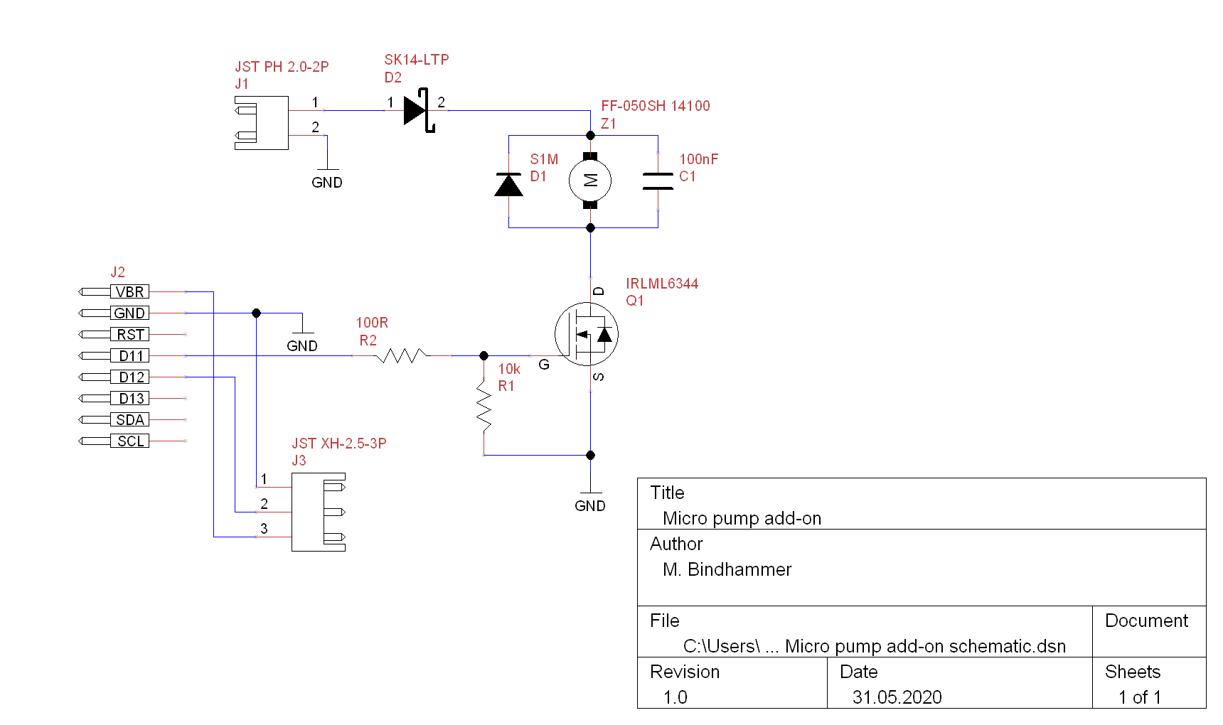
As already suspected, the silicone seals the small pump very well, it can now easily be used for water. The pump draws about 500mA during operation, which is quite a lot, even if PWM is used later. The motor is a fake Mabuchi FF-050SH 14100, a FF-050SH 07400 would be better, it has a much lower revolution speed and draws much less current. But since I didn't find a source of supply, I decided not to exchange the motor and to run it with a LIPO. Here is the schematic of the micro pump add-on, to which the soil moisture sensor is also connected:
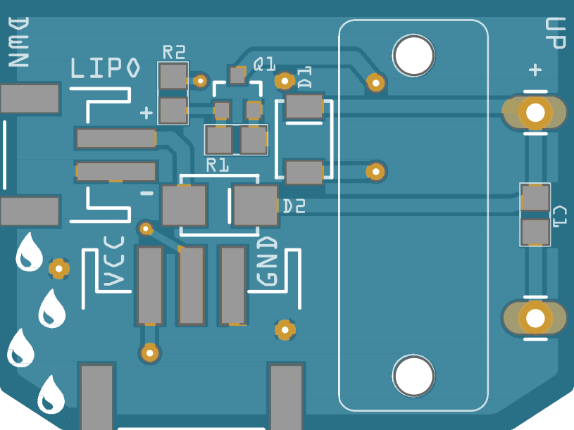
The PCB dimensions are the same as for the FM radio, 34.5 x 26mm:
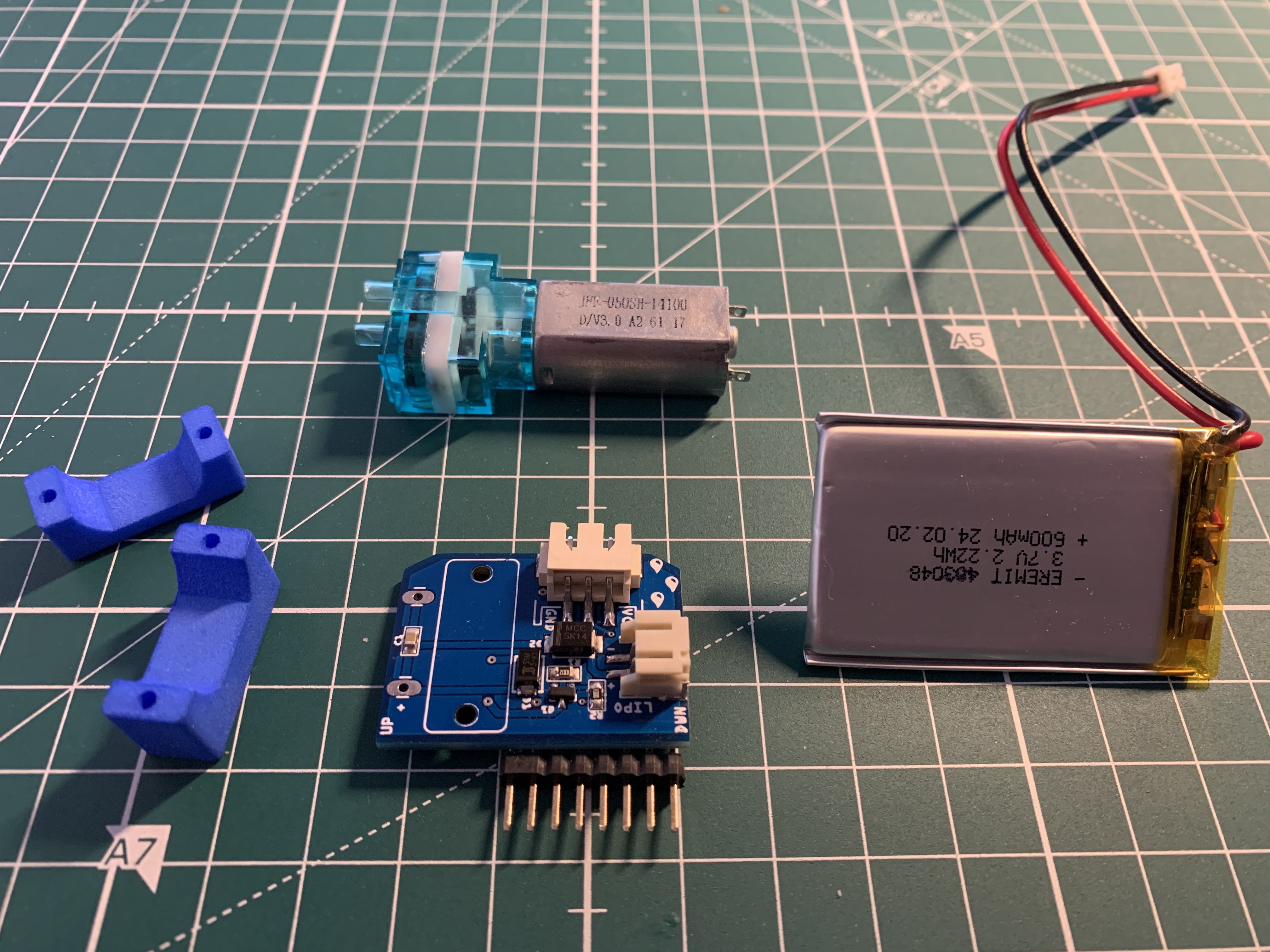
3-D printed micro pump holder, populated PCB, LIPO battery and modified micro pump:
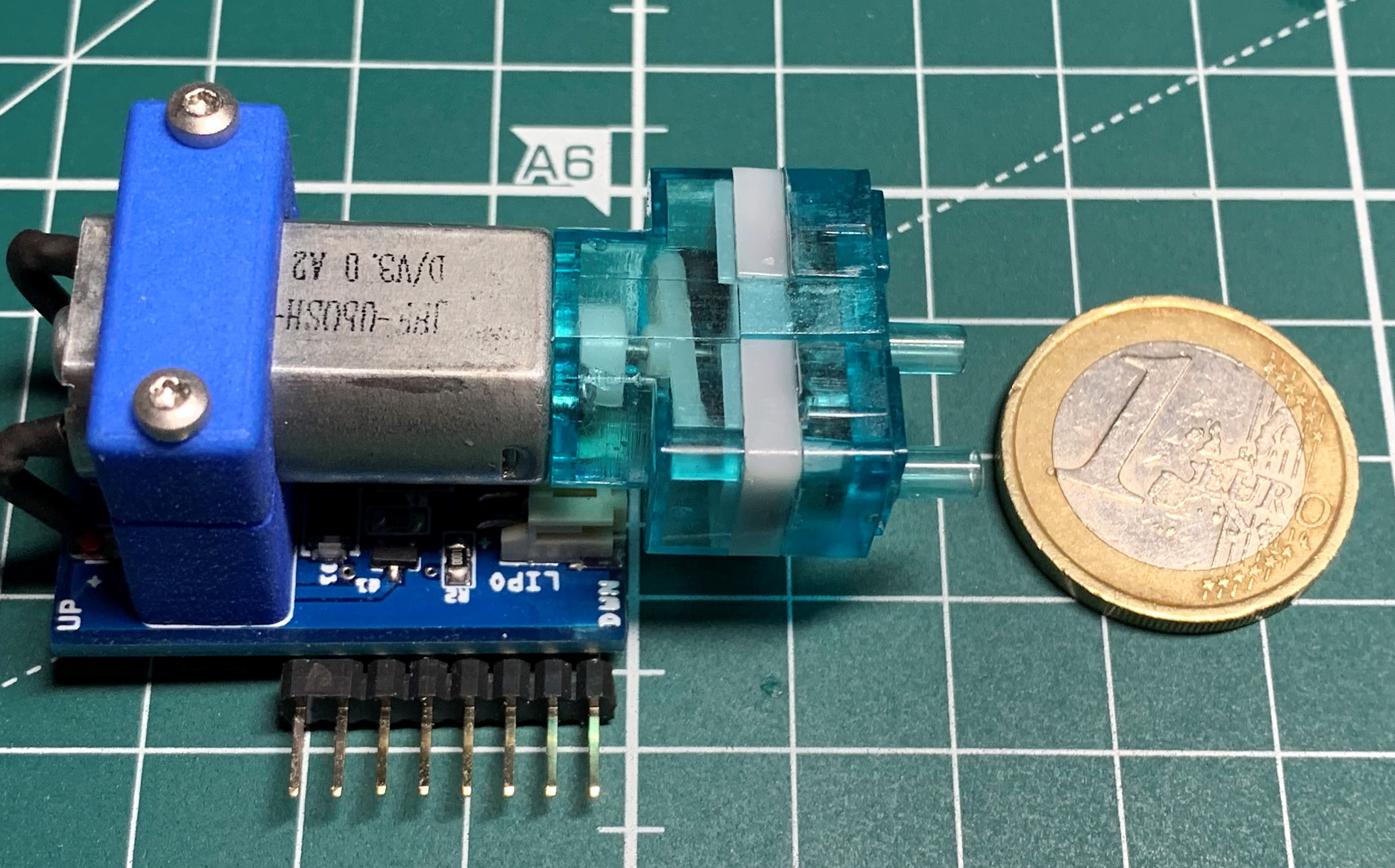
Finished micro water pump add-on:
Discussions
Become a Hackaday.io Member
Create an account to leave a comment. Already have an account? Log In.