 UTSOURCE
Step 1: Things You Need
For Transmitter
- 434 MHz RF Transmitter Module
- HT - 12E Encoder IC
- 750 KΩ Resistor
- Push Button
- Power Supply
- Connecting Wires
- Prototyping Board (Breadboard)
For Receiver
- Arduino UNO
- 434 MHz RF Receiver Module
- HT - 12D Decoder IC
- 33 KΩ Resistor
- Small Buzzer
- Power Supply
- Connecting Wires
- Prototyping Board
Step 2: Schematics
Design of Transmitter Circuit
The transmitter consists of a 434 MHz RF Transmitter Module, HT – 12E Encoder IC, 750 KΩ Resistor and a push button. The design of the transmitter circuit is very simple. Pins 18 and 9 are connected to supply and ground terminals respectively.
The data out pin (Pin 17) of HT – 12E is connected to data pin of the RF Transmitter Module. A 750 KΩ is connected between the oscillator pins (Pins 15 and 16) of the HT – 12E. The transmission enable pin (Pin 14) is connected to ground. A push button is connected between AD8 (Pin 10) and ground. Other connections are shown in the circuit diagram.
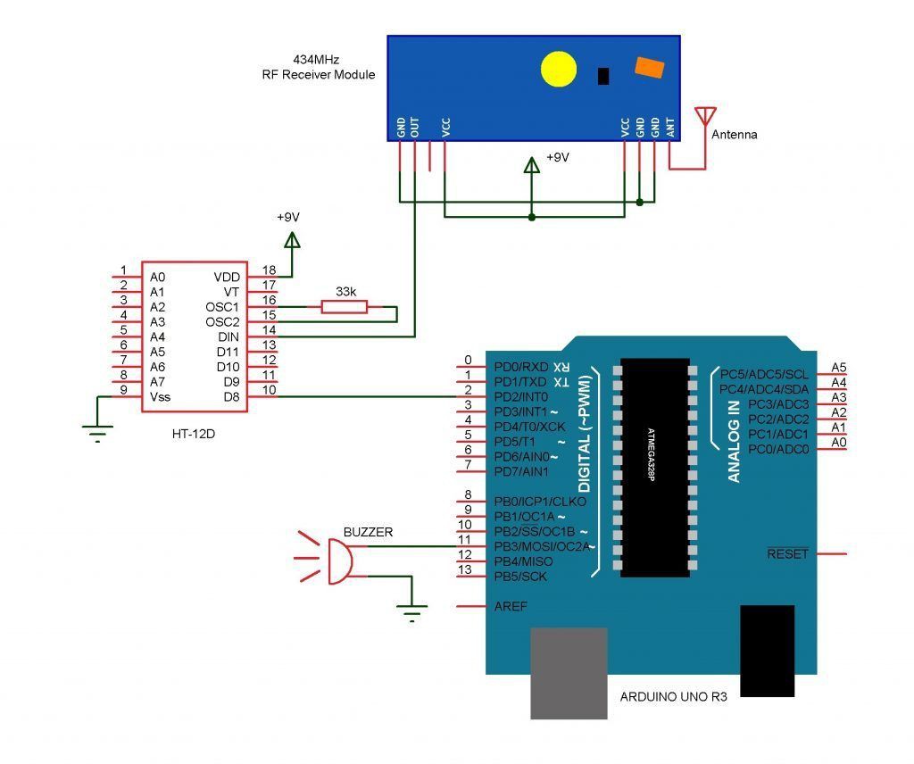
Design of Receiver Circuit
The receiver part of the project consists of 434 MHz RF Receiver Module, HT – 12D Decoder IC, 33 KΩ Resistor, Arduino UNO and a small buzzer.
Pins 18 and 9 i.e. VDD and Vss pins are connected to supply and ground terminals respectively. The data in pin (Pin 14) of the decoder IC is connected to the data pin of the RF Receiver Module. A 33 KΩ Resistor is connected between the oscillator pins (Pins 15 and 16) of the decoder IC.
The D8 pin (Pin 10) is connected to Pin 2 (or any digital I/O pin) of Arduino UNO. A small buzzer is connected between pin 11 of Arduino and ground.
So, connect everything according to the shown schematics.
Step 3: Code
You need to upload the following code to your arduino Board :
int buz=11;
int sen=2;
void setup()
{
pinMode(buz,OUTPUT);
pinMode(sen,INPUT);
digitalWrite(buz,LOW);
digitalWrite(sen,HIGH);
}
void loop()
{
while(digitalRead(sen)==HIGH);
digitalWrite(buz,HIGH);
while(digitalRead(sen)==LOW);
digitalWrite(buz,LOW);
}
Step 4: Final Step
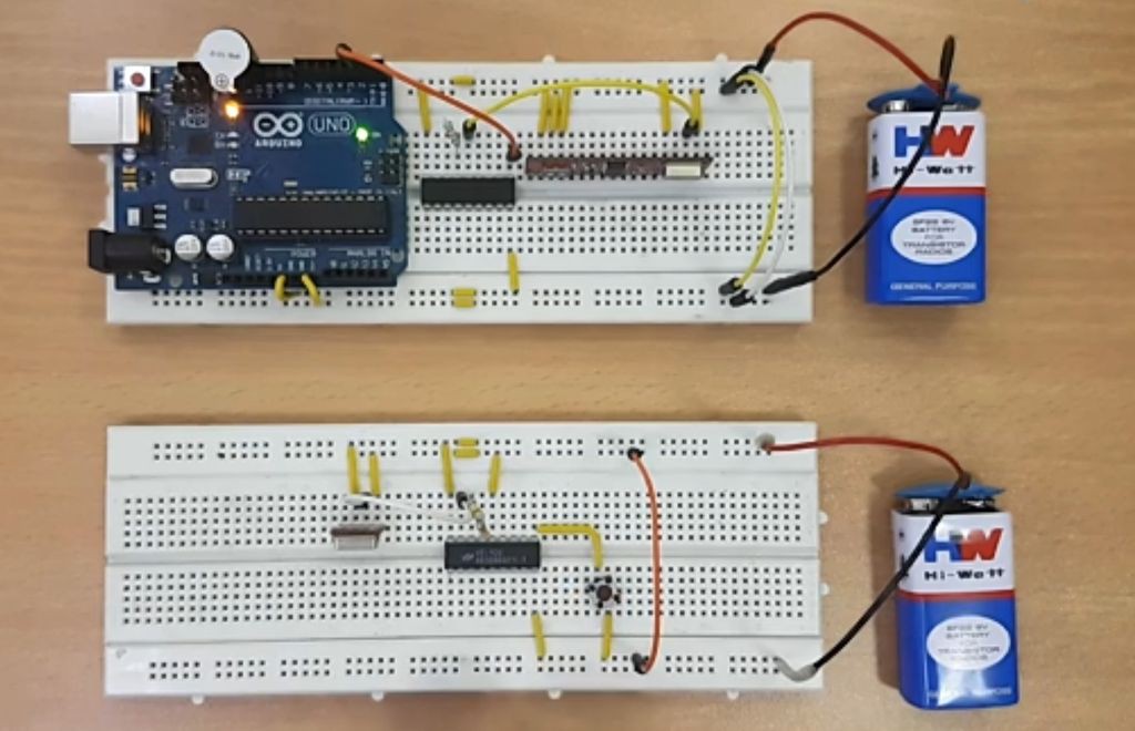
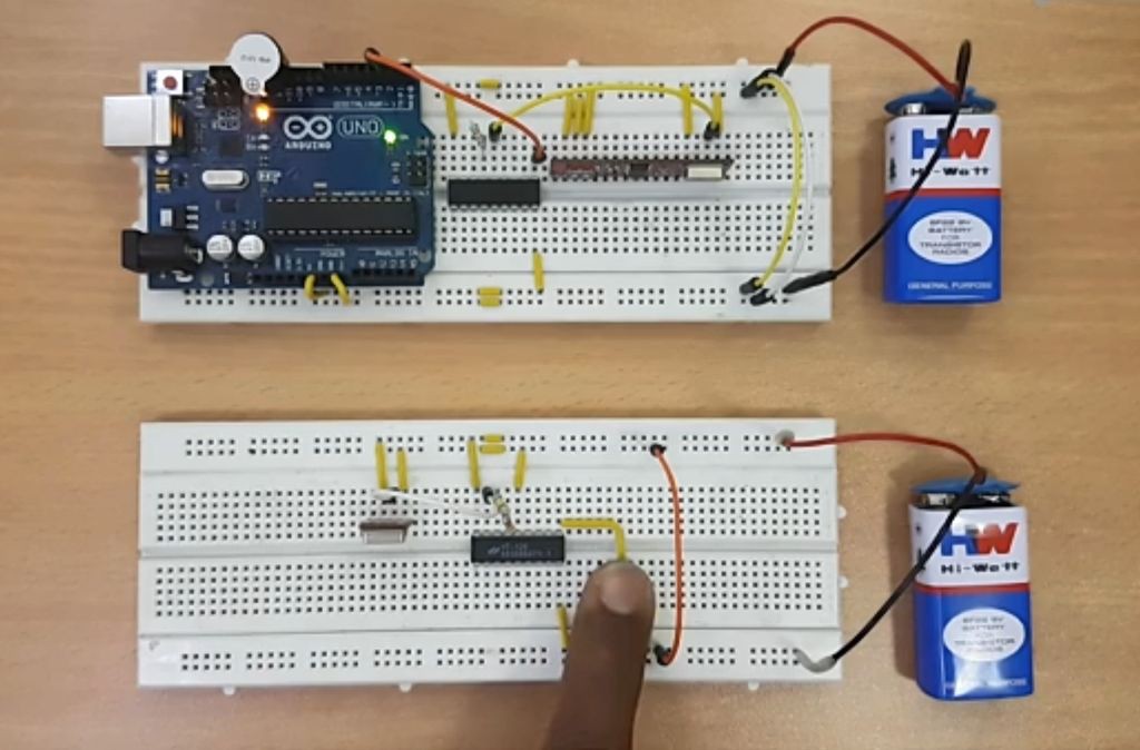
So, after connecting everything together and uploading the code to Arduino it takes us to the final step of this project and it is testing the doorbell so whenever you press the switch at transmitter end the BUZZER on the receiver end will start making sound. So finally our doorbell is ready up and running and you can make a PCB of this project and put it in a enclosure box and put it on your door.
 electronicsworkshops
 Hulk
Hulk
 eGuidezhan