What is Massage Gun?
JLCPCB: Massage guns offer what's known as percussive or vibration therapy. This type of massage provides rapid bursts of pressure into the body's muscle tissue (hence the rippling effect of massage guns) as its head oscillates back and forth. Masseurs and masseuses have traditionally used a series of light strikes from the hands or wrists to the given muscle group to get this effect.
Step 1: Main Components
1. Battery: adopt lithium-ion battery 18650 2200mAH four strings with protection plate 14.8v
2. Charger: Output 18V 600mA input AC 100-240v exposed line 1.5 meters long
3. Motor: brushless motor BL42351 3800RPM DC12V
4. DC socket: 5.5mm aperture direct plug
Step 2: Function Setting
Single-button: press once to start-up to enter 1 -2 -3 -4 -5 -6 - shutdown, cycle operation. Press the button for 2 seconds to shut down. Gear position blue light digital tube display

Step 3: Power Indicator
1) working and standby: three blue lights --100%; Two blue lights --60%; A blue light --30% 2) charging: when plugged into the charger, the blue light flashes: 30% -- the first blue is always bright, the other two blue lights flash;60% of the time -- two blue lights are always on, the other blue light flashing;100% time -- three blue lights are always on 3) intelligent timing: timing 10 minutes, digital tube countdown, began to display 10, count back 9, 8, 7......2,1,0 when it comes to 0, the motor automatically stopped, into standby station. Standby state, the motor does not work, only show electricity. In standby mode, all lights will be off when there is no button action for 5 minutes.IC goes into hibernation power-saving mode.
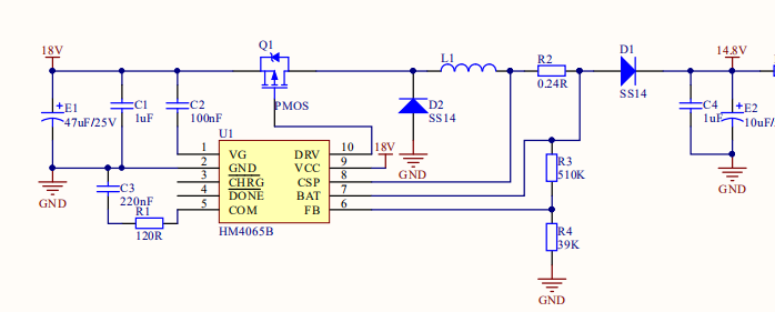
Step 4: Schematic View of Massage Gun

Step 5: Circuit Scheme
EasyEDA : Charger: input AC 100-240v, output DC18V.The battery is 4 series 18650 with a nominal voltage of 14.8v. It is necessary to control the step-down IC to realize charging. Here, HM4065B is selected.Specific parameters: 1-5 section can be set switch type, external MOS 6.6v-30v expansion 4A 1mA 1% adjustable/reference voltage 1.2v 300KHz SSOP -10.When the charger is connected, it can be directly detected by MCU after passing the partial pressure.
For PCB design , recommend Easy EDA
PCB Prototype, you can choose JLCPCB , you can get 5 pcs by $2

Step 6: MCU Can Use 7550

You can easily get the main components from LCSC
Step 7: MCU

The MCU I use is a Sonix OTP 8-bit control chip, a very cheap one,but it only can be programmed once.
Step 8: Battery Detection and Motor Control

Step 9: Gear Display and LED Display

gear display requires digital tube for display, while LED display is enough for power and charging display
Step 10: key Switch


 Vipin M
 Chris Chung
why buy this without a soul device. If you can visit a great erotic massage in Australia - https://eroticmassagebrisbane.com/