The specific open source licenses that RX-Modulus will use are also somewhat in flux. Anyone who has developed a product (particularly one that includes Hardware, Firmware and Software), knows that this landscape is somewhat convoluted. I still struggle with wrapping my head around what is best for us.
We plan to certify the hardware as open source through the OSHWA certification process but the specific license for that is still being decided. The Firmware content RX-Modulus will be published under a Creative Commons Attribution Non-Commercial License. Any OS software will likely be published under BSD.
But, as I said, we are still evaluating all of this stuff. The plan is to have it decided before the end of the year, well in advance of our public release. If anyone has any comments or ideas about this, I would love to hear them. Please feel free to reach out.
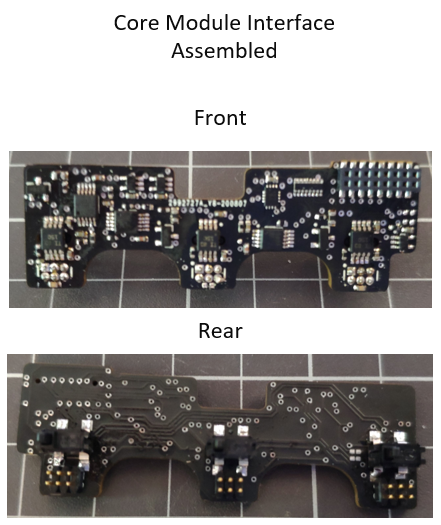
Just a sneak peek at some of the assembled boards of our project. Certainly having a SMD part stencil came in very handy adding the quite small QFN components.
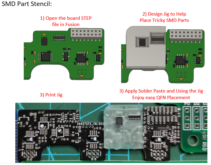
SMD Part Stencil:
While I have placed QFN packages before with success for small batch prototypes there is always the chance of placing an expensive IC incorrectly will resulting in costly reworking. For certain elements of this project I have made Part stencils to help with tricky parts and parts that require aligning. Making a Part stencil is very simple and can be done in a few ways from using a 3D Printer to a laser cutter. For me using my resin printer which the best option has a can achieve a very respectable 0.05mm tolerance. Once you know what parts you would like help placing its just 4 easy steps for accurate and repeatable placement. Of course these can be lost if have access to a PnP machine but it's certainly a good start.
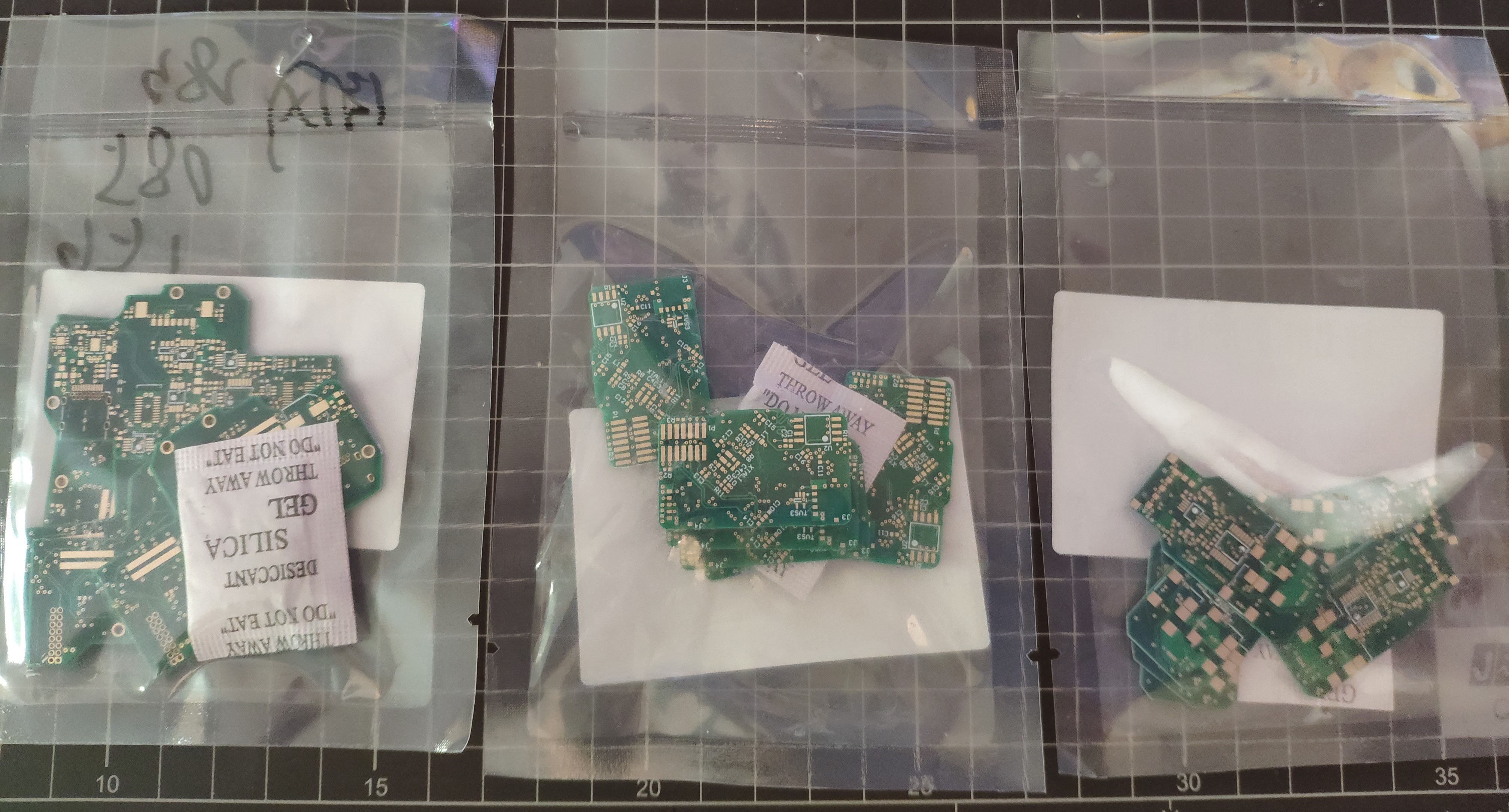
Bare Board PCB Arrivals:
High-P Core.
Core Interface.
Adaptive Interface Module.
These certainly arrived sooner than I planned and but a nice surprise.
The parts are on order and will be fully assembled shortly.
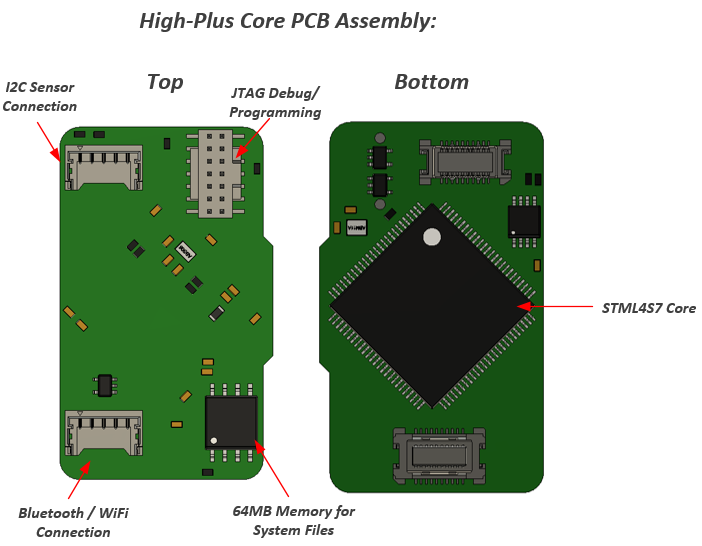
Some of you many remember that I'll be creating a special Adaptive Interface Core which features a few extra connections for sensors and wireless modules which will aid the adaptive interface set for UCPLA. Well this is now a reality please welcome our new High-Plus Core:
Overall High-Plus Core Features:
- Powerful STM32L4S7 Core
- Supports Changeable Micro-controller Core
- ESD Protection
- 64MB Memory running at 80MHz for system files and offline GIF and Picture storage for Touch-D Modules.
- Extra Interfaces can be added via the I2C Sensor connector for more functionality.
- Connection for Bluetooth / WiFi Modules to be connected.
Progress:
Both the High-Plus Core and Dev Interface PWA will be going into prototype manufacture in the next couple of days.
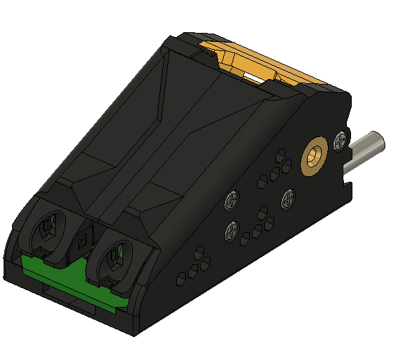
After a few weeks of development I'm happy to showcase the First Adaptive Interface Module for the RX Modulus.
What is this module for?
Users with greater disabilities might find having a mouse be too hard to handle. The idea behind the Adaptive Interface Module is to allow for commercial/open source adaptive devices to be plugged into our project turning it into a modular 'mouse' into a 'interface' which the user can use easier than having the RX in its mouse form.
The RX Module set can also be extended to suit. The RX can still be used as a computer mouse interface in this configuration but can also be used to control or interface with other devices. As the firmware will be open source the swap from ‘mouse’ to ‘interface’ to easy and additional code modules can be added to enable control to other devices/equipment.
Features:
1) Supports all Adaptive interfaces and controls which are designed to be used with a Microsoft Adaptive Controller. Also applies to any opensource interface as well which is designed to use a 3.5mm jack.
2) Adaptive Control circuity ensures that any connected adaptive interfaces can be driven safely and correctly without using dedicated ports. Both ports can be configured to the following: GPIO/Analogue Mode (with selectable power rails and hardware pull-up/down resistors). This ensures that anything from push buttons to joysticks and foot peddles can be used on each channel.
3) Features a extra mode, 'RX_EXT_I2C' comms mode this allows RX-Modulus Modules to be extended further away from the core. Depending on the user's disability they might only want to handle one Touch-D module with a side pack for example. For this mode to work both channel 1 and 2 are used.
Connections: 2x 3.5mm 4 pole (max) connectors. 2 and 3 pole connections are also supported.
When Incorporated into the RX Modulus Core a total for 8 channels are available. This is certainly a good amount for a few joysticks and a handful of other interfaces for example. The amount of channels could be increased if the module is set to RX_EXT_I2C comms mode and a interface extender is used. (Could be developed in the future if required).
Plenty of Opportunities:
Progress:
The Prototype Module PCB is currently in manufacture.
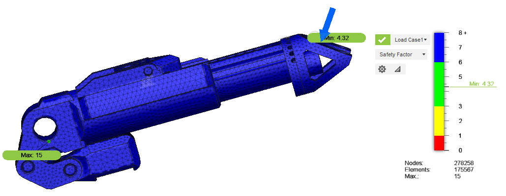
Each element of the RX-Modulus was first simulated with a force of 49N (5Kg) applied, which is quite a notable weight to apply down using your hand. For example the Adjustable Palm support was tested in its fully extended mode which is its weakest position. All elements and modules are tested in there weakest position. The part was simulated with a material property of ABS plastic which is 98% identical to the resin I'm using for this prototype.
The testing showed that the part can easily support 49N (5Kg) and with a safety factor of 4.32(min) the part can support be weight of 211.68N (21.6kg) before failing. Now this is virtual so to cover all the bases all parts are then physically tested.
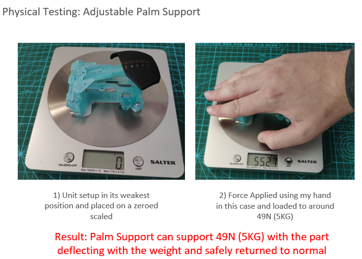
2) Physical Testing:
In my eyes Simulation gives me a warm feeling that at-least the part is strong virtually but nothing is better than physically testing a item. There are many ways to test this item but the testing of the Adjustable Palm support was easy all I needed was some scales.
The results of the test are very promising as the deflecting due to the weight actually acts as a spring which is actually a nice feature this element has.
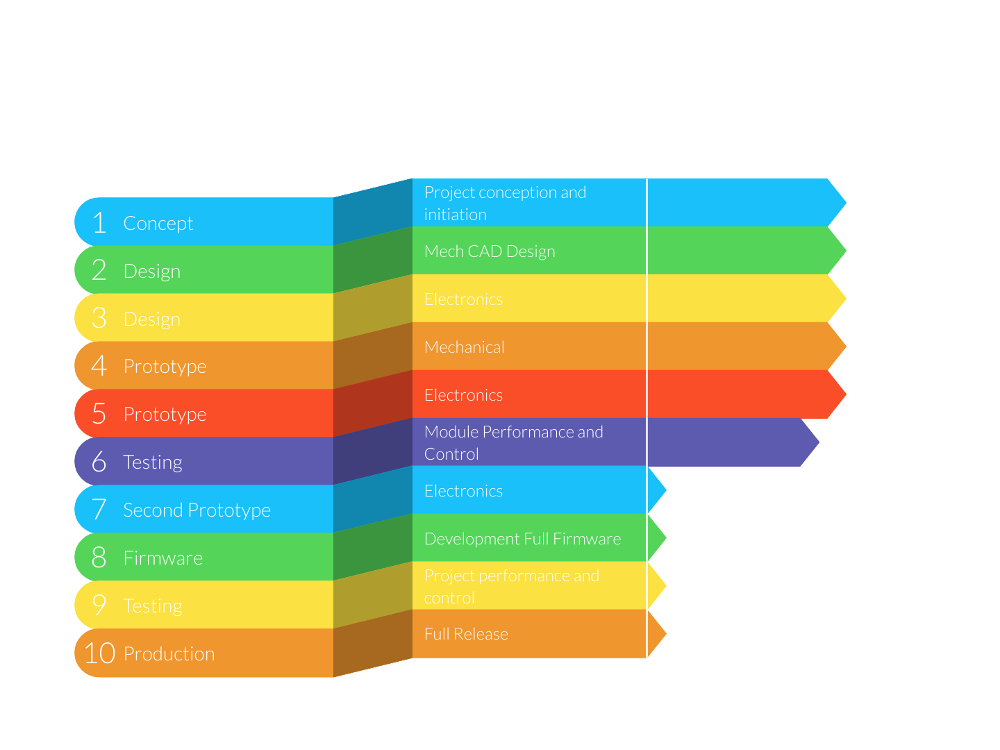
How are the Electronic aspects tested?
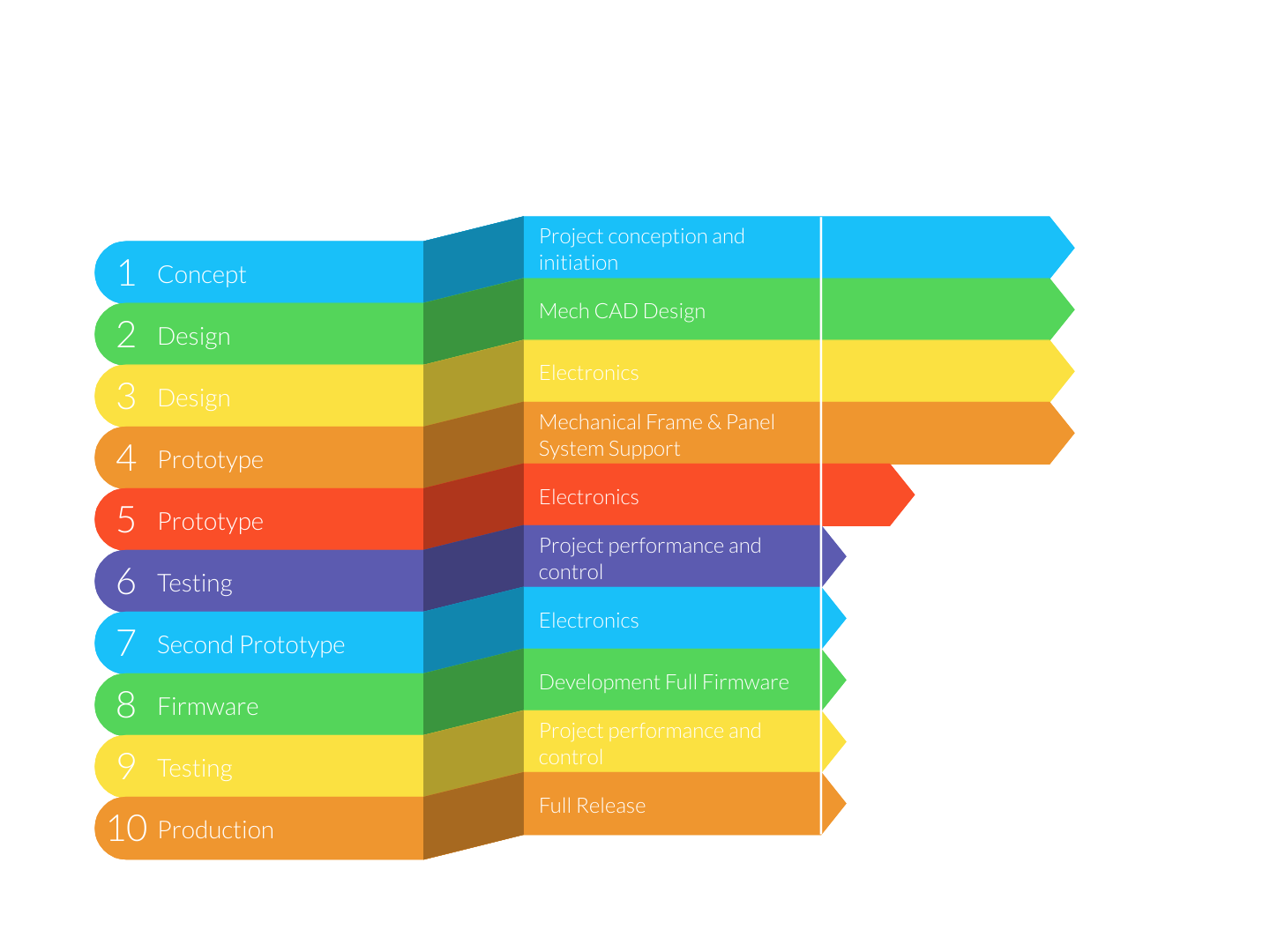
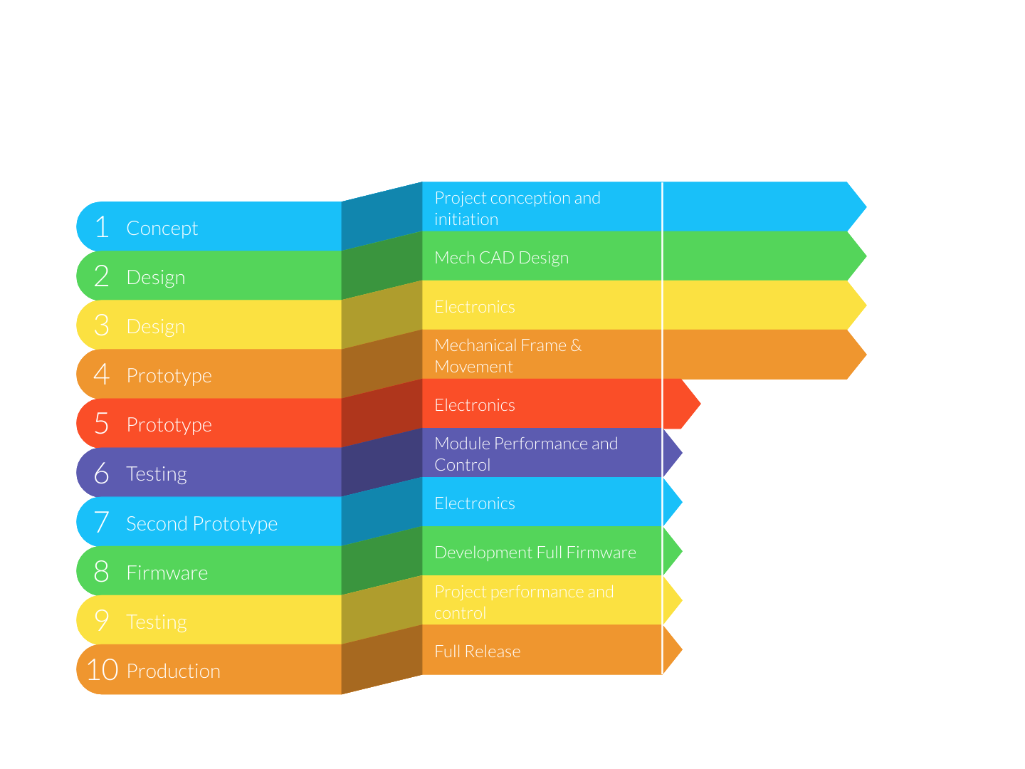
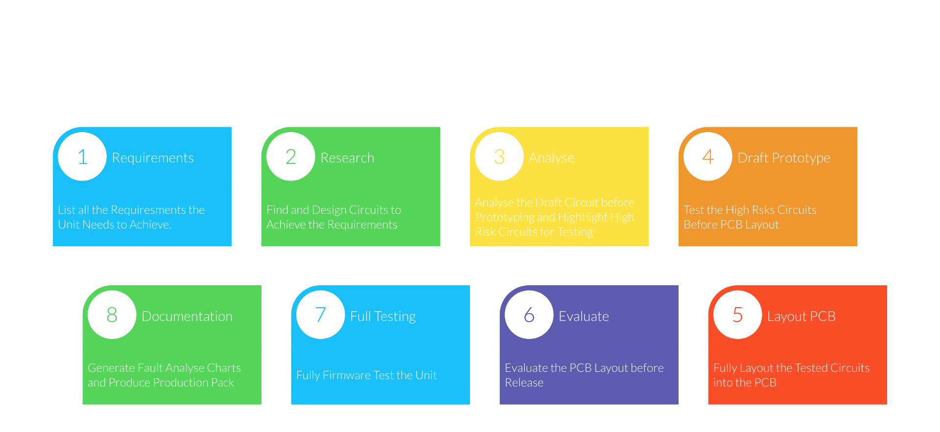
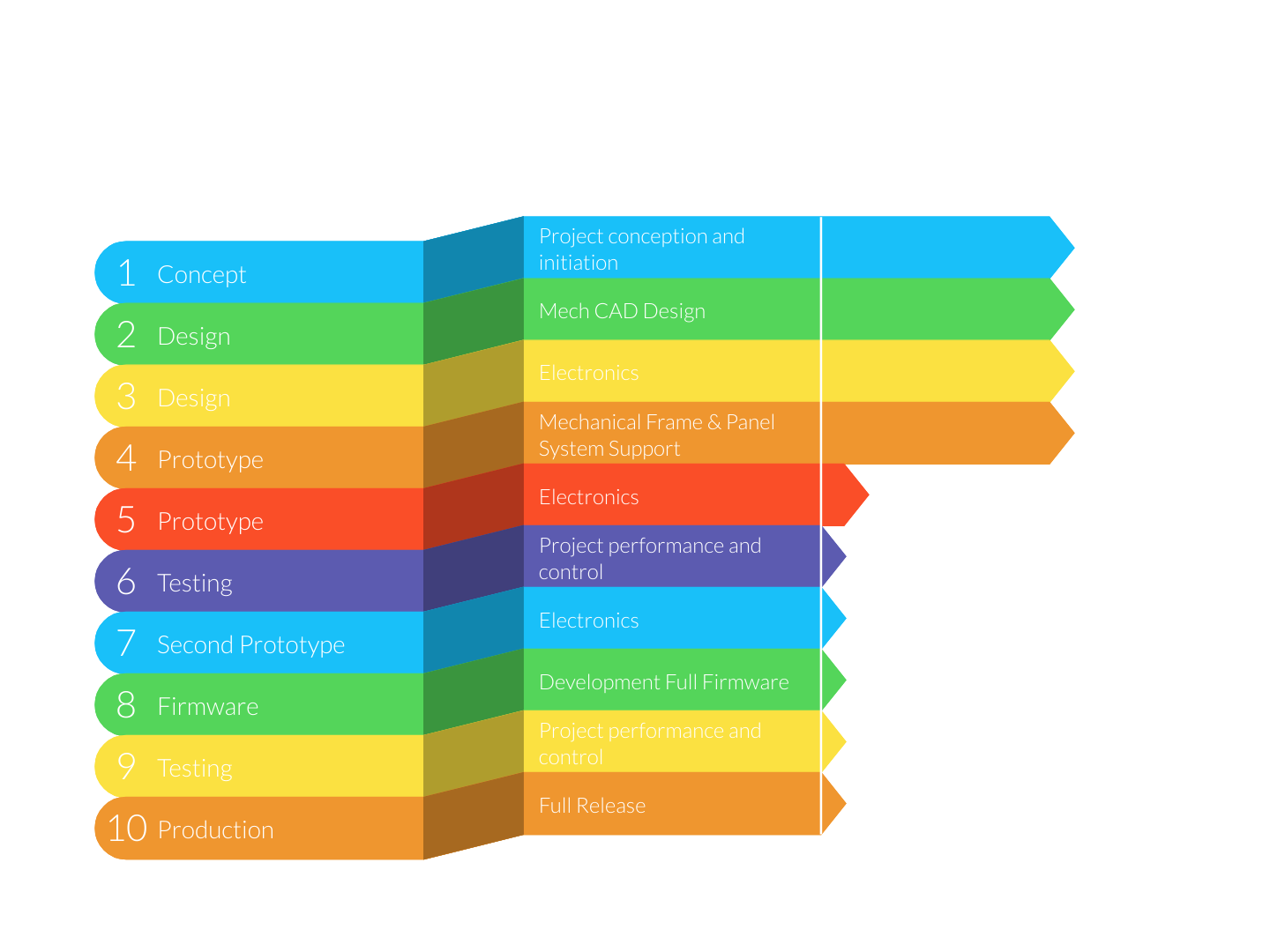
The chart below shows the basic steps we take when developing any electronic element of these project.
Note: If a issue is found that requires circuit fixes and new PCB's at step 7 we would jump back to step 4.
We have a whole suit of tools and equipment to help us test the electronics. For the Touch-D module the most helpful tool is the Digital Discovery (Logic Analyser). This tool would allow us to test all comm busses and ensure that all GPIO are being driven correctly.
How will the Firmware be tested?
The Digital Discovery (Logic Analyser) is also very important when doing the firmware testing. There are two methods of testing that are done these are:
1) Standalone Testing:
Standalone testing is done first with the unit, in this case the Touch-D module is driven standalone from the rest of the system. As the analyser and send and receive I2C data. We use the Digital Discovery (Logic Analyser) to pretend to be the core unit master. This gives us a stable, fast and reliable testing structure.
2) Integration Testing:
After we are happy with the Standalone testing we will then conduct Integration testing. This would be done after the Core Unit has been fully tested, if we were testing a module like the Touch-D. At this stage all performance checks are made and recorded before full release.
Documentation:
After Hardware and Firmware Testing on electronic elements all the production files will be release to ensure we have stable and known working items. At this stage will be also be creating Fault Analysis Charts to help the user fault find. There will be a basic chart as shown below that only require basic testing and fixes. An Advanced Fault Finding Chart are to be released for people that have technical knowledge and basic electronic tools and wish to fix the boards themselves.
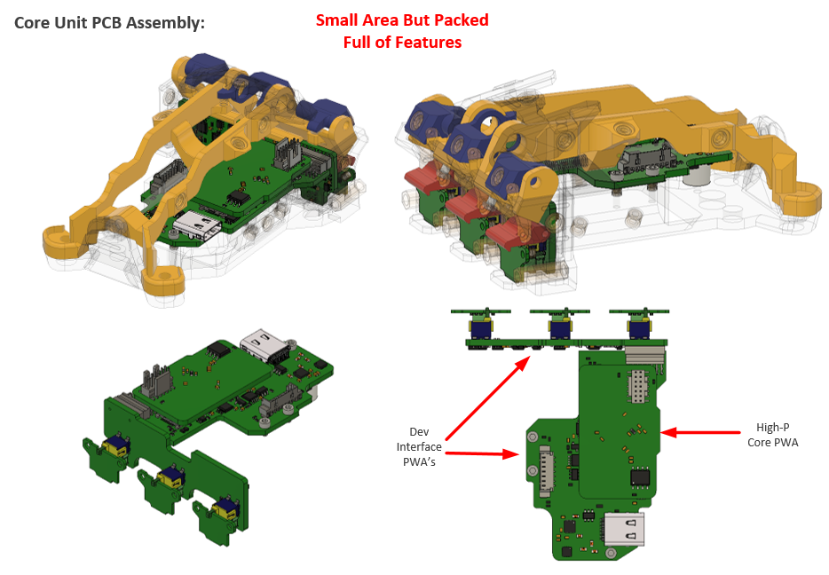
Here is the current progress of the Core Unit for the RX-Modulus Project.
We will be soon releasing the first batch of PCB's for Core Unit very soon.
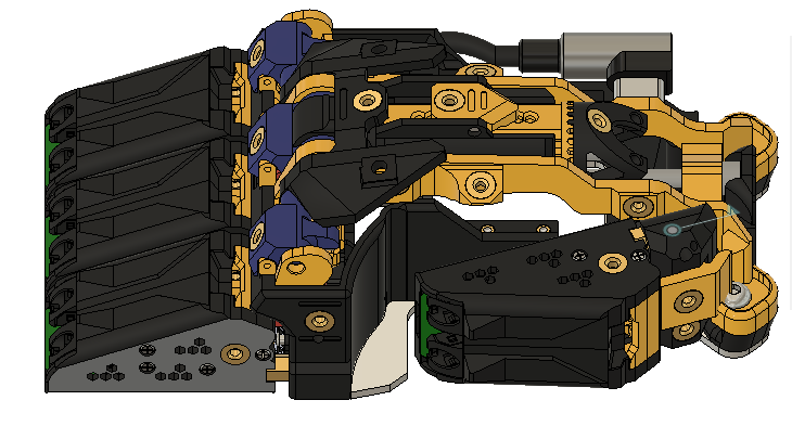
Now it's time to uncover the mystery of whats in the Core Unit.
As you can see there is certainly alot going on in this unit. The boards that are worth the biggest mention is the Dev Interface PWA and the High-P Core PWA.
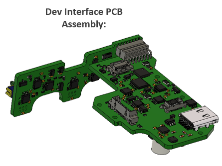
Dev Interface PWA:
This assembly of boards is responsible for interfacing with and powering all the modules and Core PWA. The Dev version has been development with robustness and checking features in mind. All module interfaces are Hot-Swap compliant with all the ESD protect one could wish for, so modules can be safety removed at any time and not damaged the system. Safety and Measurement features have been added to monitor system and module voltage and current levels with safety shutdowns if modules fail. The Dev Interface also features a Changeable Core System, where micro-controller cores can be changed and upgraded with minimal hardware change and waste. After the first build a lite version of this board will be developed as a cheaper alternative for people that want the deceased amount of protection at a cheaper price.
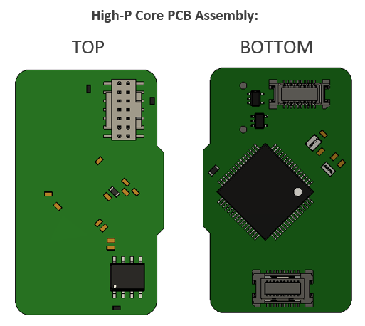
High-P Core PWA:
This PWA is the brains of the whole project and is responsible for setting up the mouse to the users configuration, heath monitoring and communication with all connected modules to a host machine via USB-C connection (When using the Adaptive Interface Set the project can be set to interface mode to control other devices via wireless for example). We are currently developing the High-P Core to be based around a STM32 F4 with extra memory (Could be change to G4) Core. As this board is compatible with the Changeable Core System we have the ability to redesign a more powerful or less powerful/cheaper cores without redesigning the whole mouse. We will soon be developing a special Adaptive Interface Core which features extra connections for sensors and wireless modules which will aid the adaptive interface set for UCPLA.
Overall Core Unit Features:
- Powerful STM32 Core
- Changeable Micro-controller Core
- Hot Swap Compliant
- ESD Protection
- Voltage and Current Levels with safety shutdowns for all modules
- USB-C connection to host with PD Control.
- Extra Interfaces can be added for more functionality.
Here is the current progress of the modules for the RX-Modulus Project.
Basic & Touch-D Module:
Currently testing all the interfaces of this module and have found a few issues and improvements on the core PCB which require a second prototype to be made.
SMART Module:
All interface have been tested and shown to work. Just waiting for the module core to be tested on the second prototype on the Basic & Touch-D Module.
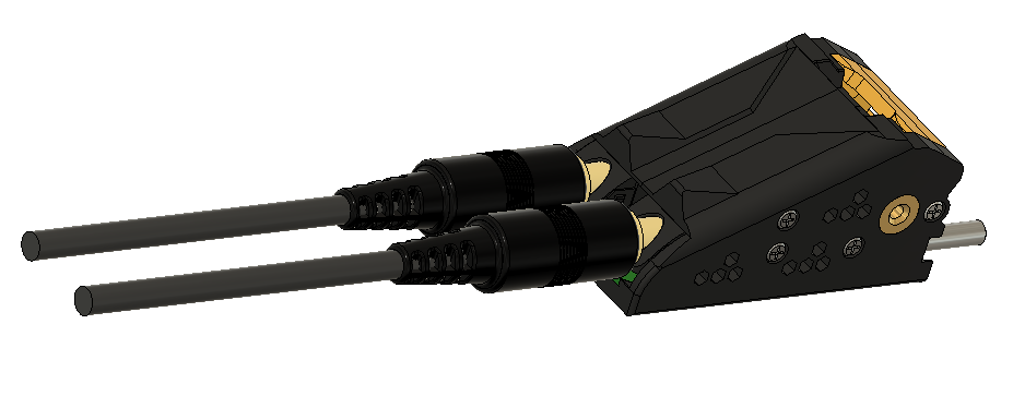
Laser Positioning Module Set:
This module has been tested on the very first prototype about 2 years ago. The newer version has been designed to fit the new shape of mouse. This module also features a higher resolution sensor.
Adaptive Interface Module Set:
After a successful mentor session with the great people from UCPLA we now know that designing the drafted adaptive module set will greatly help those that the UCPLA support. As way got the go ahead from the UCPLA only last week this module set hasn't matured like the other modules but we can take on board all the lessons learnt from all the other modules currently is the first prototyping loop and aim to achieve 'Right First Time'.
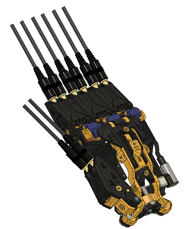
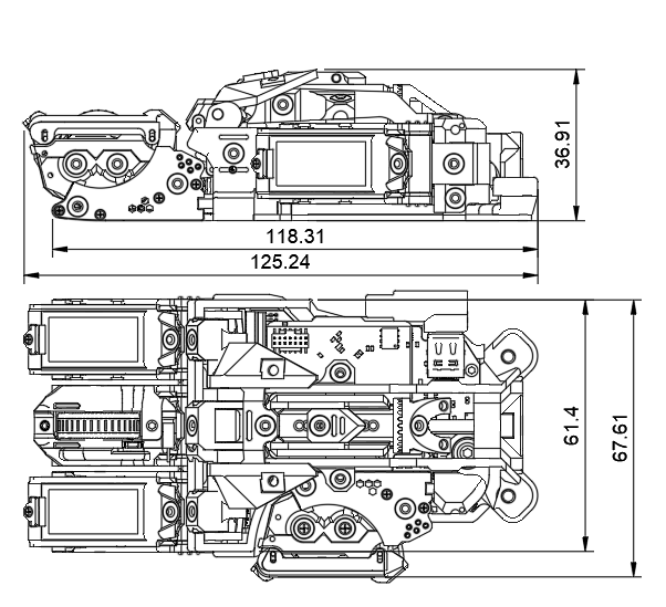
As been asked by our great community many questions about this project but the question that comes up the most is the size. So with that said here is the answer.
Note: As the project can change sizes the current full range is:
Length: Min 110mm, Max 140mm
Width: Min 61.4mm, Max 80mm (with larger panel set)
Height: Min 37mm, Max 55mm (with palm rest at max swing)
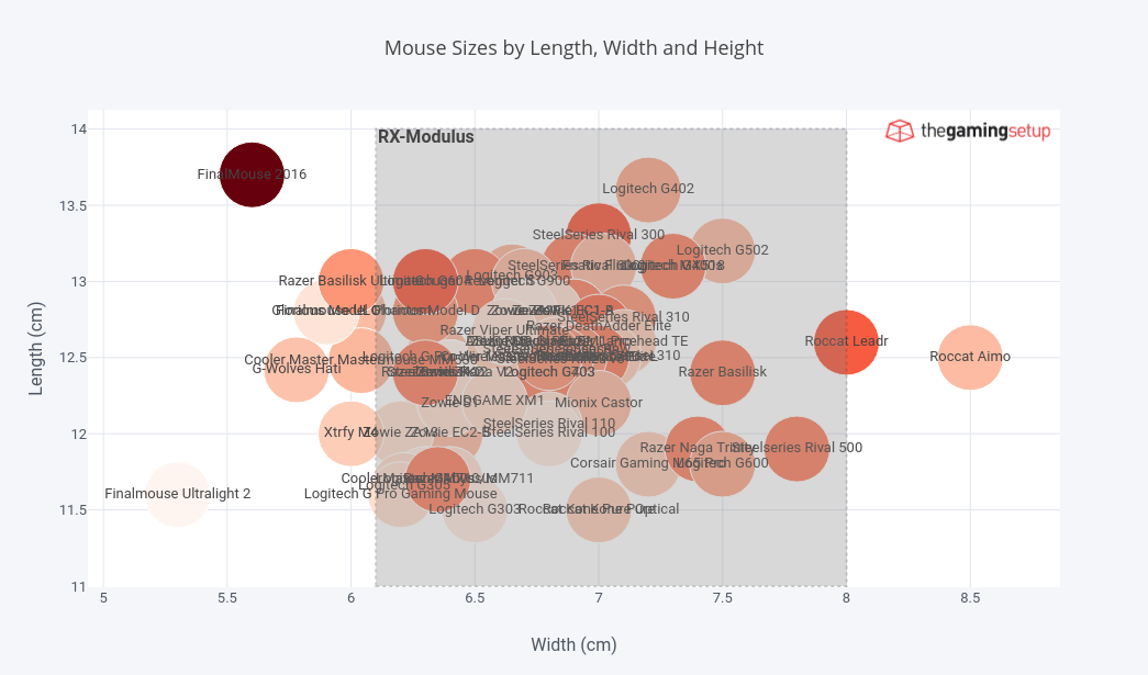
How does the size of the RX-Modulus compare against other mouses:
I've added the size range of the RX-Modulus onto the chart.
As you can see the RX-Modulus size range encompass about 90% of the available mouses on the market, which isn't too bad if you ask me.
So what does this mean?
Well it would certainly see like the old saying "There’s no perfect mouse for everyone, it depends on a bunch of factors, grip type, play style and hand size" Has been overcome with this project as this mouse successfully adapts to all the factors mention. At this time RX-Modulus is suitable for the full range of hands sizes.
Small: Under 16.9cm
Medium: 17-19.5cm
Large: Over 19.6cm
As a comparison my hand measures out to 18cm length and 9.5cm width and makes me suitable for medium or large size range of the mouse.
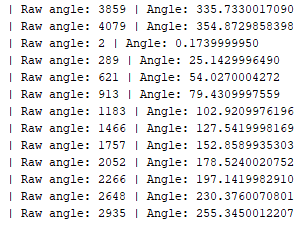
About two updates ago I mentioned that the scroll wheel positioning sensor working great with very impressive accuracy. For that test I was using the Ams development tool which was connected via I2C to the module. This software was a good start but it was time to write some trial Arduino code and grab some useful data. The useful data in this class is Raw Angle (Range 0 -4095) and Angle (0 -360).
Each bump step on the scroll wheel is spaced at 24 degrees (14 bumps per full rotation on this bump plate) there's about 1 degree of play on the bump plate at the moment. The angle measurements above can be corrected by setting the '0' position but for a simple test I am happy with the results.
Why use a Contactless Encoder:
I've actually been asked this a few times and yes there are two simpler ways of doing this: one being optical the other being the standard encoder. I went with the magnetic method as it wears less then standard methods and also allows for greater control of where the scroll steps are. This is especially useful as the bump plates can be replaced with different profiles that might feature less or more scroll step feedback bumps. While the control method used is I2C there are two ways that can be used to find the position of the wheel one being I2C and the other being Quadrature Encoder Output. There is pro's and con's on both but I've written and tested both methods to increase the ever growing flexibly of this project.
Community Startup:
From today I'm pleased to announce that we have opened a Official Discord Server for RX-Modulus. We hope it will became the start of a larger community to ask questions, quickly interact with the team, help others, share ideas and designs to developed this project further. Of course anyone can still write comments on the Hackaday project page and the project page and logs will keep being updated (I'm still around and online on Hackaday). Just moving some of the specific background project discussions and sharing of ideas and files on Discord as its cleaner and easier to manage. A GitHub server will be made once more firmware has been developed and when I'm happy to release the electronic files and STEP models for the mouse. To start people off designing their panel sets and possible module add-on's.
If the embedded link in the image does not work please use the following link:
 benw
benw