Digitspace were kind enough to send me a free voucher for the two main parts of this project:
In return, I agreed to write up the project here. It looks like makers are free to submit their own requests for sponsorship via their website.
ESP32-based tracker, LoRa beacon and road-quality monitor
Already have an account? Log in.
To make the experience fit your profile, pick a username and tell us what interests you.
Digitspace were kind enough to send me a free voucher for the two main parts of this project:
In return, I agreed to write up the project here. It looks like makers are free to submit their own requests for sponsorship via their website.
Since the last update, I've continued making bits of sporadic process.
I've:
So I'll break those down a bit more here.
The FIT (Flexible & Interoperable data Transfer, apparently) file format is a very flexible, openly documented data format used by a bunch of different GPS/activity tracker products, with the main driving force seeming to be Garmin (perhaps via their acquisition of Dynastream?).
There's an SDK available for download, which includes the various specifications and a tool for generating C/C++/C# and Java code to encode and decode fit files: https://www.thisisant.com/developer/resources/downloads/
As far as flexible data interchange formats go, FIT is fairly sane and well thought out.
The whole file format is based on "messages", where a message is just a set of fields. Each field has a type, which can either be a base type like "uint8" or "string", or a more specific enumerated type such as "WorkoutStep" which uses one of the base-types as its underlying representation. All of these messages and types are defined in a big spreadsheet in the SDK.
A FIT file consists of a header stating what kind of file it is ("Settings", "Device", "Activity" etc), and a series of messages with the actual content.
The file protocol allows for only encoding the fields which you actually care about, so even though the "Lap" message which stores data about a lap has 114 fields defined - from start time and position to "avg_saturated_hemoglobin_percent" - you only actually have to encode the fields you care about, and all decoders will gracefully handle the difference.
While I'm usually pretty cynical about proprietary file formats, I really do think FIT's a pretty elegant and effective design, and it's worth having a read through the documentation in the SDK.
FIT has the concept of a "profile" which is the subset of messages and fields that a particular device supports, and the code generator can generate suitable code for that profile. So, in order to generate just the code and definitions that I need for my particular project, I had to write (modify) a "profile.csv" file, which is the input to the code generator. In the .csv file you state which messages and fields you want, and then the Windows-only code generator will spit out C/C++/C#/Java code for it for you.
I wrote a very thin wrapper over the top of the generated code, which gives me just enough to create the FIT files I need. You can see the result here: https://github.com/usedbytes/tbeam-fit
The next piece is the network service, which interfaces with the ESP32 WiFi and HTTP request libraries.
It's got two main responsibilities:
I'm not entirely happy with the request interface, but it does provide a pretty flexible way to perform network transactions, which should work fine for this project and is probably applicable to other projects, too.
The main interface is this structure:
struct network_txn {
    struct service *sender;

    esp_http_client_config_t cfg;

    // Content-Type header
    const char *content_type;

    // Callbacks for performing send and receive
    network_txn_send_cb send_cb;
    network_txn_receive_cb receive_cb;

    // Filled in by transaction handler
    esp_err_t err;
    int result;
};
The caller fills in the 'cfg' structure with things like the URL, and provides two optional callbacks: 'send_cb' and 'receive_cb', then it sends a pointer to this request structure to the network service.
The network service...
Read more »It's been a little while since I posted an update here, but I have been doing some work in the meantime, slowed down a bit by illness, decorating, and the new 8 GB Raspberry Pi 4 getting released.
Let's start with that:
<tangent>
I've been keen for quite some time on using Arm powered machines for as much as I can. Back in 2103 I bought the first Samsung Chromebook which used a dual-core Cortex-A15 Samsung Exynos chip, and I used that as my main laptop until I eventually bought an Intel Inside Thinkpad at the end of 2016. My main machine at my day job is an Arm powered HP Envy x2 with a Snapdragon 835, but at home I've been using an i5 2500k desktop for the past 10 years. I've been itching to try and replace at least some of that machine's time with something Arm based, but the devices just haven't existed. They're all too underpowered (Cortex A53 cores), too low on RAM (less than 8 GB), or too pricey (the $4000 Ampere eMAG desktop). I came very close to picking up a Honeycomb LX2K, but before I actually did, the 8 GB Pi 4 was announced (somewhat out of nowhere) - so that was a no-brainer: A usable amount of horsepower (4 x A72), with an excellent software ecosystem, for less than £100. I bought one on release day.
So, since then I've been leaving the i5 desktop turned off and using the Pi 4 almost exclusively. I've installed tuptime to see how much time I use each machine for, and I expect I'll do some more blogging about my experiences over on my blog at https://blog.usedbytes.com.
Anyway, how is any of that relevant? Well, this ESP32 project is my primary project at the moment, so I need to be able to work on it on the Pi 4.
</tangent>
To set-up the ESP-IDF development on a Pi 4 I did have to do some messing around. I'm running the new 64-bit Raspberry Pi OS image, which means it's a native arm64 system. ESP-IDF doesn't have any support for arm64, and therefore some hoops need jumping through.
Espressif do provide builds of their tools for 32-bit Arm, which we can use. They also provide source code for all of them. I started out by building the Xtensa toolchain using Espressif's crosstool-ng fork, and their decent instructions: https://docs.espressif.com/projects/esp-idf/en/latest/esp32/get-started/linux-setup-scratch.html
It took about 2 hours on the Pi 4, building on an SD card, which to be honest isn't too bad (my desktop probably would have taken half that. I'm sure a fast modern high-core-count x86-64 machine like AMD's Threadripper could do it in minutes).
I found that this was only the first step. Upon trying to run the ESP-IDF install.sh script it started complaining about the other tools I was missing. Frustratingly, the first one was xtensa-esp32s2-elf-gcc - You need a whole separate toolchain for the new "S2" version of the ESP32, even if you aren't planning to target it!
Anyway, I set up crosstool-ng to build that toolchain too, and left it another two hours.
After that, you need the binutils for the low-power coprocessor, as well as an openocd build - and I didn't feel much like building those from scratch so I started trying to use Espressif's 32-bit Arm prebuilt packages.
There are some threads on the Espressif forums about modifying the "tools.json" file to add an entry for arm64 which refers to the "linux-armel" binaries, but I just went the manual route of downloading the packages and putting them on my $PATH.
Next issue is when you try to run any of the arm32 components, you see the unhelpful error:
$ openocd
-bash: /home/pi/sources/esp/openocd-esp32/bin/openocd: No such file or directory
I've done enough working with Arm boards to know that this usually indicates a problem with the dynamic linker/loader. The reason the message is so unhelpful is because the program really can't do anything much...
Read more »With the main components at least powered on, I need to start adding more control and purpose.
First, is being able to configure the GPS module. Instead of the default setting, I want to tell it to:
u-blox have their own command/communication protocol for their GPS modules, called "UBX" - it's all detailed in the M8 Receiver description - Including protocol Specification document.
UBX is nice and simple. Two sync characters ('µb'), two bytes of packet type information, a length field, a payload, and a checksum. So first order of business is to write or find some code which I can use to send and receive UBX messages.
There are some libraries out there:
I really don't need much functionality, so I decided to just write my own. I only plan to support a couple of messages, and the core of my implementation is around 200 lines of C - in this case I think the small targeted implementation makes sense instead of trying to integrate one of the larger more featureful libraries.
I'm still in prototyping mode, so there's no sensible encapsulation or interface definition - but the code is here:
https://github.com/usedbytes/tbeam/blob/b835efd1482f628b7bd0bb4345208d666a2bbf4f/main/gps.c
The crux of it is the receive_ubx function, which can be called with data received from the serial port. It searches for valid UBX messages, and returns them. It's stateful so you don't need to worry about messages getting split by the serial driver, you just call it each time you have data and it will return messages as it finds them. The intended usage is something like so:
#define BUF_SIZE 256
uint8_t serial_buf[BUF_SIZE];

while (1) {
        len = serial_receive(serial_buf, BUF_SIZE);

        uint8_t *cursor = serial_buf;
        while (len > 0) {
                // On success, receive_ubx() will update 'p' to point just
                // after the end of any message it finds.
                uint8_t *p = cursor;
                struct ubx_message *msg = receive_ubx(&p, len);
                if (msg != NULL) {
                        // Do something with msg
                        free(msg);
                } else if (p == cursor) {
                        // Something went wrong - bail
                        break;
                }
                len = serial_buf + BUF_SIZE - p;
                cursor = p;
        }
}
... but I've realised in writing this log, that:
So I'll probably refine that a bit.
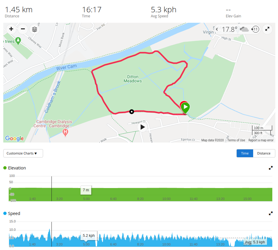
Anyway, my transmitter and receiver code is functional, so I've used it to send a:
And then use the receiver to receive UBX-NAV-PVT messages and decode them into (Timestamp + Longitude + Latitude).
Next up I need somewhere to log the GPS data. I don't have an SD card on my board (I kinda forgot about that - some of the TTGO boards do, but not this one), so the only non-volatile storage I have available is the main flash of the ESP32.
ESP-IDF has a spiffs implementation, so I've set up a 1 MB partition to write the data to. Right now I'm writing 16 bytes every second, which will fill up the megabyte in ~18 hours. That's OK - but perhaps a little on the short side. Also once I start logging more data (acceleration, battery etc.) it would reduce, so I'll probably implement some kind of simple compression scheme (store difference from previous sample or something).
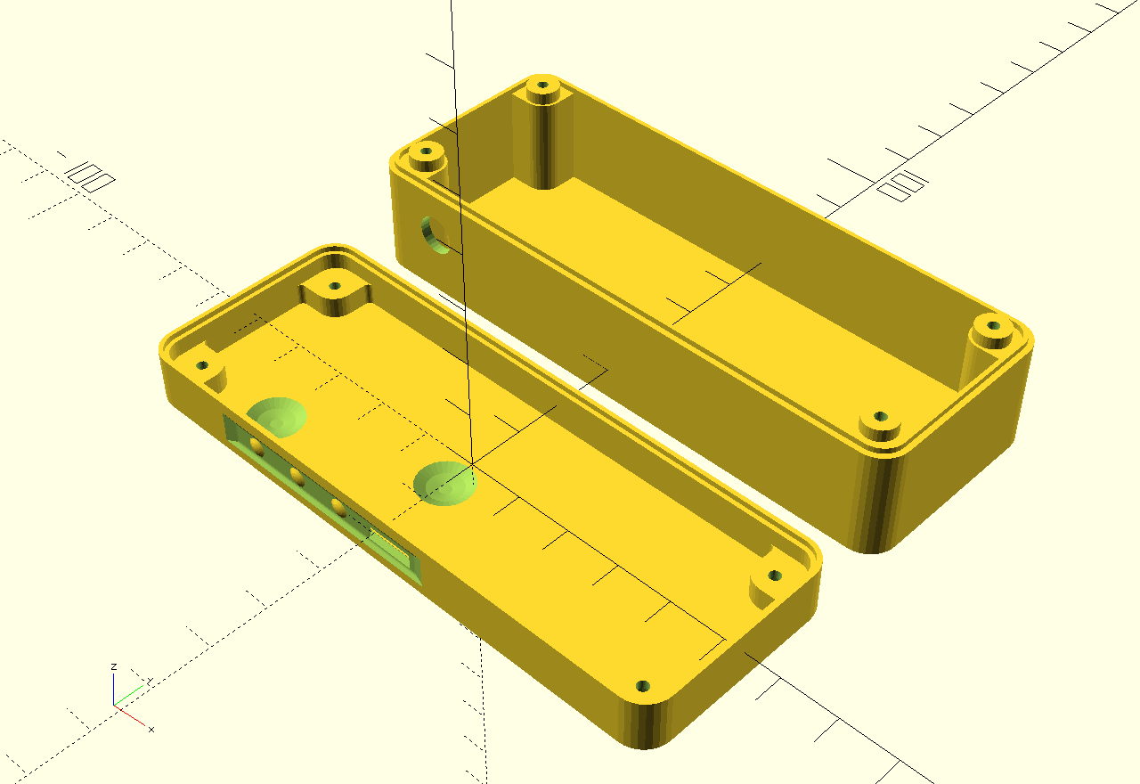
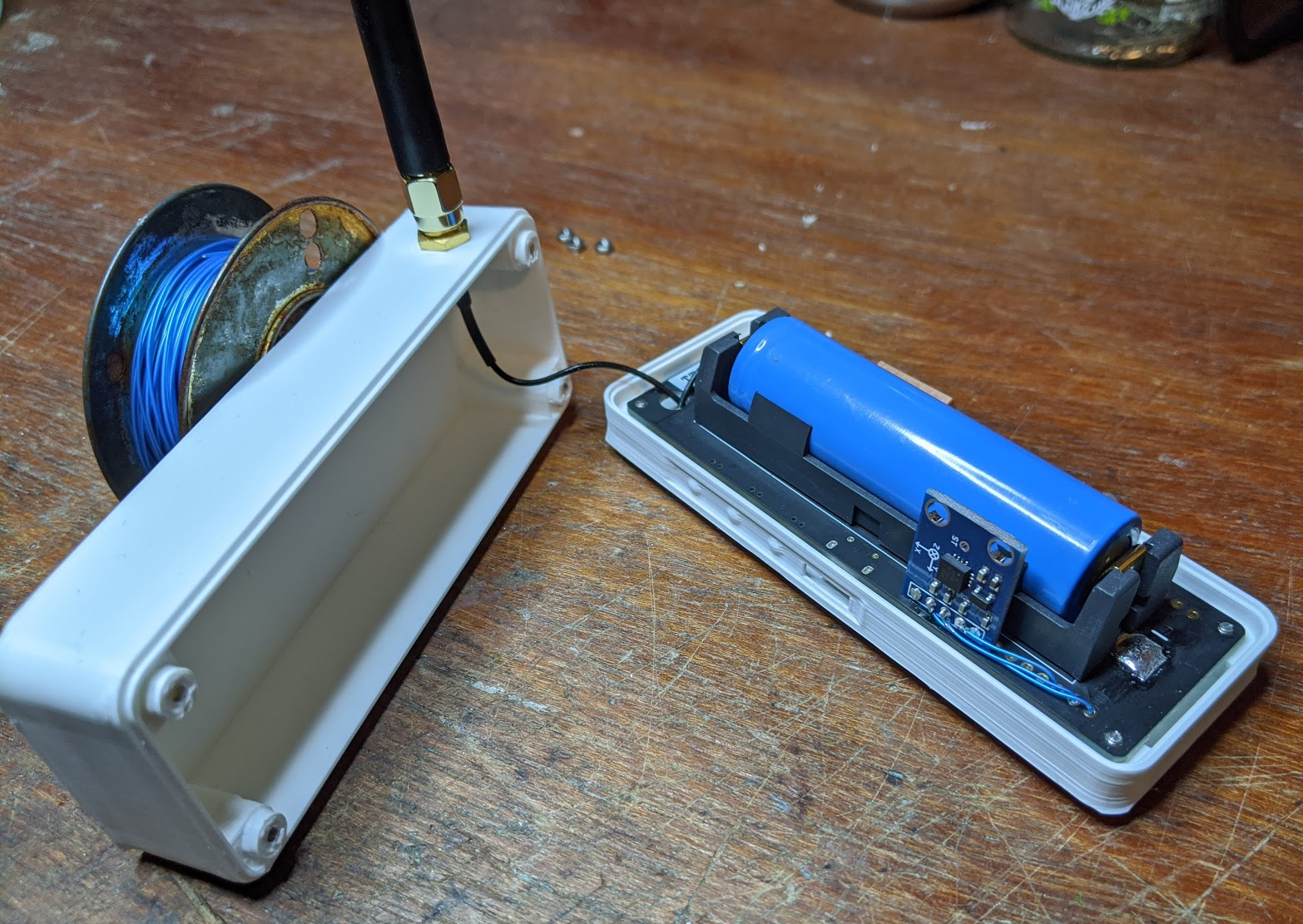
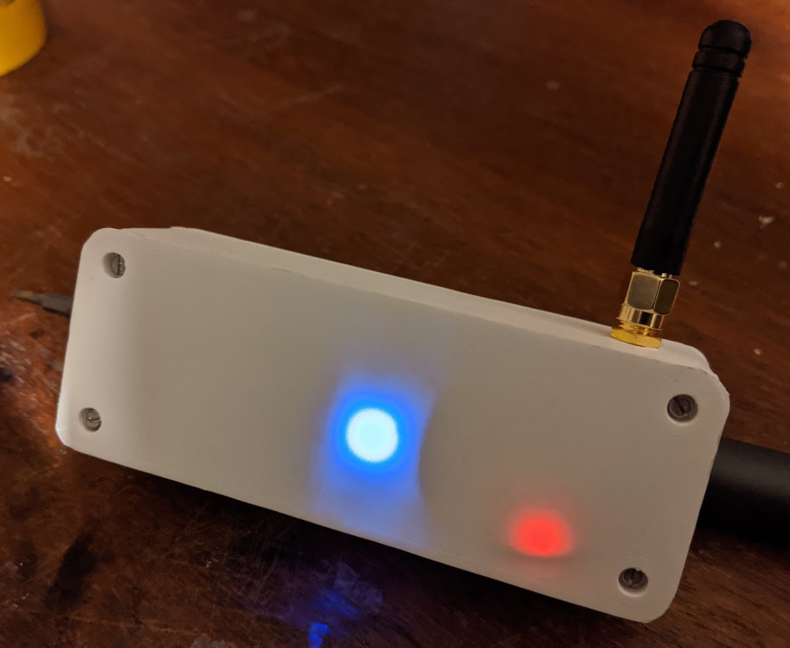
Next up, I've designed a case to keep everything secure and together. There are a few T-Beam cases on Thingiverse already, but they all seem to include the OLED which I don't have, so I jumped into OpenSCAD to design my own.
I made the base thin over the two LEDs so that they can shine through (at least somewhat), and also made the wall thin next to the buttons, with little protrusions which are meant to push onto the switch. I made the clearance just a little too large, so it's quite tricky to push the buttons, but it will do for now.
I've pushed the CAD files (and code updates) to my repo on GitHub: https://github.com/usedbytes/tbeam. It's all very messy at the moment while I'm prototyping, but I'll be neatening it up as I move towards the final implementation.
I also soldered in my accelerometer. It uses analogue outputs, which is good for my use-case because I want to monitor it during deep-sleep, and that seems easier to do on analogue pins than having to handle i2c traffic from the ESP32 low-power coprocessor code.
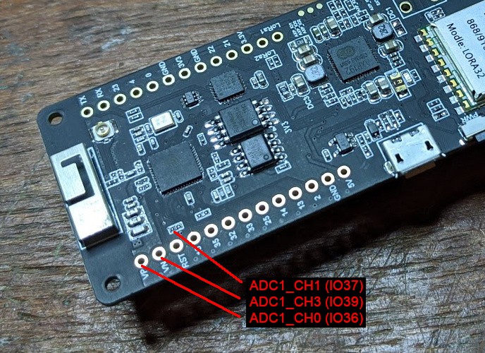
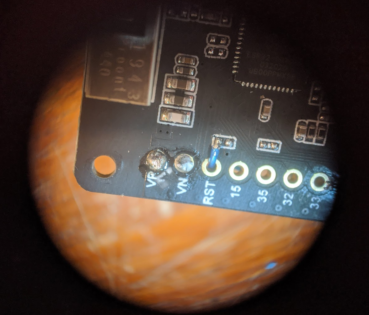
I found the ESP32 documentation around the ADC routing a bit confusing, but did eventually identify three pins which I can access on the T-Beam, and that can be used for ADC1 from the low-power coprocessor.
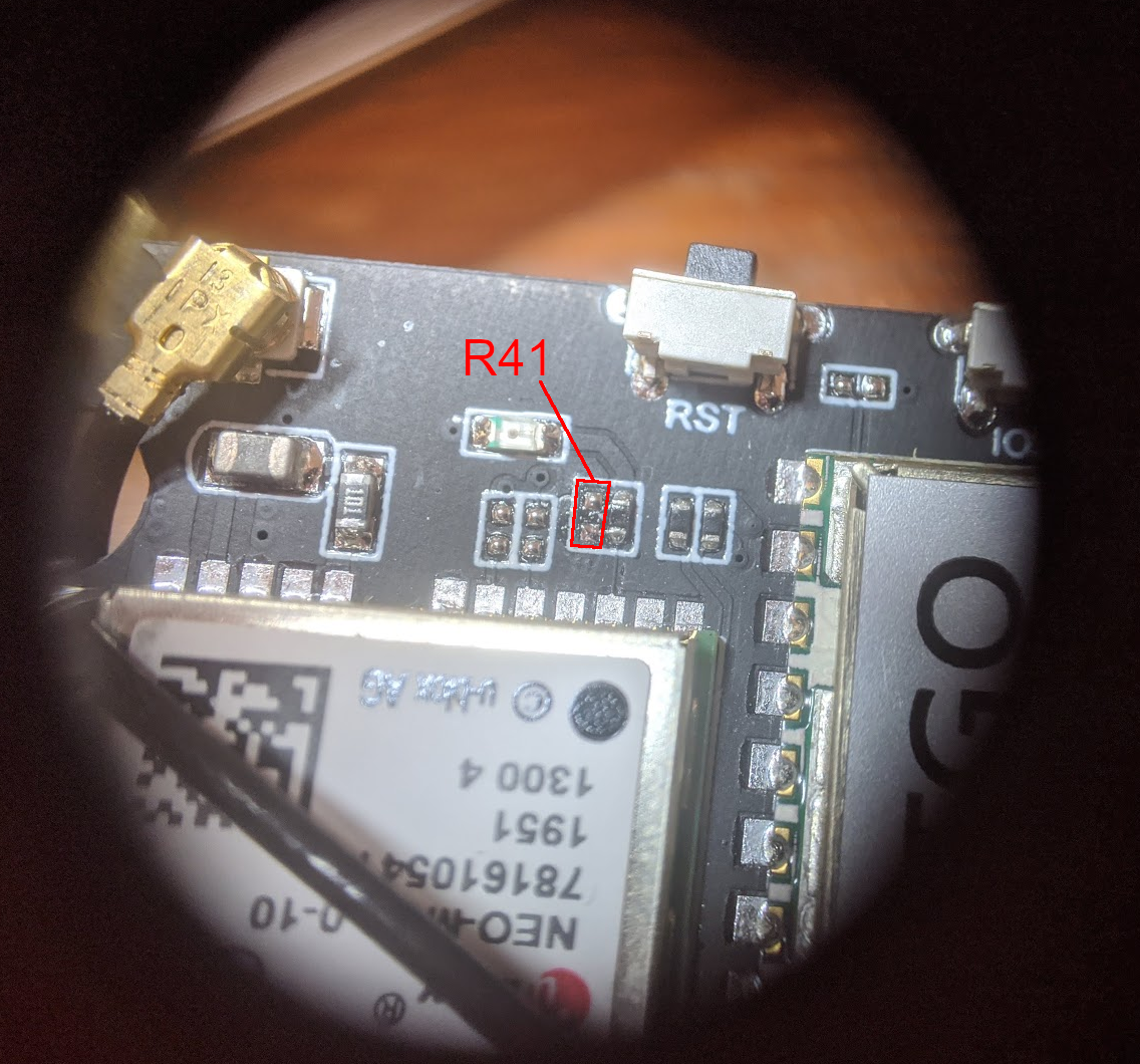
The T-Beam's RTC + ADC1 GPIOs are pretty well filled up with the board's functionality. I found three pins I could use. Only two of them are broken out to pads on the headers, the third (IO37) is available as a pad on one of the not-populated 0402 components. Annoyingly, IO37 is also wired to the GPS module time pulse output, so I had to remove R41 to disconnect that. I'm not planning to use the time pulse, so this shouldn't really be a problem - but if I do want it I will just wire it to a different pin.
The not-populated pad is R67 in the schematic, and the pad closest to the WiFi antenna is IO37. VN and VP are for the internal hall effect sensor, but I don't plan to use that so I'll use those.
I've wired the accelerometer VCC pin to IO25. It's meant to have a very low active current (400 uA, not that I believe it) - so a single GPIO should easily be able to source enough current, and having it on a GPIO makes it easy to turn on and off. It's probably more efficient than spinning up the unused AXP192 DCDC1 output, too.
Which a tiny bit more code, I can read out the voltage for each axis:
// Power up the accelerometer VCC GPIO
io_conf.intr_type = GPIO_INTR_DISABLE;
io_conf.pin_bit_mask = (1ULL << GPIO_NUM_25);
io_conf.mode = GPIO_MODE_OUTPUT;
io_conf.pull_up_en = GPIO_PULLUP_DISABLE;
io_conf.pull_down_en = GPIO_PULLDOWN_DISABLE;
gpio_config(&io_conf);

gpio_set_drive_capability(GPIO_NUM_25, GPIO_DRIVE_CAP_1);
gpio_set_level(GPIO_NUM_25, 1);

// Set up the ADC channels
adc1_config_width(ADC_WIDTH_BIT_12);
adc1_config_channel_atten(ADC1_CHANNEL_0, ADC_ATTEN_DB_11);
adc1_config_channel_atten(ADC1_CHANNEL_1, ADC_ATTEN_DB_11);
adc1_config_channel_atten(ADC1_CHANNEL_3, ADC_ATTEN_DB_11);


while(1) {
        int val0 = adc1_get_raw(ADC1_CHANNEL_0);
        int val1 = adc1_get_raw(ADC1_CHANNEL_1);
        int val2 = adc1_get_raw(ADC1_CHANNEL_3);
        printf("0: %5d 1: %5d 2: %5d\n", val0, val1, val2);

        vTaskDelay(300 / portTICK_PERIOD_MS);
}0: 1535 1: 1935 2: 1915
0: 1488 1: 1948 2: 1883
0: 1515 1: 1808 2: 1789
0: 1459 1: 1801 2: 1774
0: 1570 1: 1804 2: 1808
0: 1509 1: 1846 2: 1936
0: 1508 1: 1833 2: 1917
0: 1507 1: 1857 2: 1870
0: 1453 1: 1879 2: 1889
0: 1520 1: 1840 2: 1793
0: 1577 1: 1870 2: 1744
0: 1457 1: 1861 2: 1835
0: 1574 1: 1794 2: 1745
0: 1522 1: 1818 2: 1774
0: 1487 1: 1831 2: 1847
0: 1474 1: 1814 2: 1838
Next up on my list was to get the buttons on the board working, and set it up to run on battery power.
The T-Beam board has three buttons:
Setting up the ESP32 for the USER button was simple, and I could basically use the code from the example: We just need to set-up IO38 as an input and enable a falling-edge interrupt:
static xQueueHandle gpio_evt_queue = NULL;

static void IRAM_ATTR gpio_isr_handler(void* arg)
{
    uint32_t gpio_num = (uint32_t)arg;
    xQueueSendFromISR(gpio_evt_queue, &gpio_num, NULL);
}

...

void app_main(void)
{

    io_conf.intr_type = GPIO_PIN_INTR_NEGEDGE;
    io_conf.pin_bit_mask = (1ULL << GPIO_NUM_38);
    io_conf.mode = GPIO_MODE_INPUT;
    io_conf.pull_up_en = 0;
    io_conf.pull_down_en = 0;
    gpio_config(&io_conf);

    gpio_install_isr_service(0);
    gpio_isr_handler_add(GPIO_NUM_38, gpio_isr_handler, (void*)GPIO_NUM_38);

    int cnt = 0;
    uint32_t io_num;
    while(1) {
        if(xQueueReceive(gpio_evt_queue, &io_num, 1000 / portTICK_RATE_MS)) {
            printf("Button pressed. GPIO[%d] intr, val: %d\n", io_num, gpio_get_level(io_num));
        }
        printf("cnt: %d\n", cnt++);
    }
}
Getting the interrupt from the AXP192 for the power button took a little more work. The AXP192 sets the IRQ line high when an enabled interrupt event happens, and it stays high until all of the pending interrupt events have been cleared my writing to the status registers over i2c.
So, I needed to implement some new functionality in the axp192 library to let me set up the interrupt masks and process and clear the events.
I've pushed these to my branch: https://github.com/usedbytes/axp192/blob/dev/axp192.h#L190
axp192_err_t axp192_read_irq_mask(const axp192_t *axp, uint8_t mask[5]);
axp192_err_t axp192_write_irq_mask(const axp192_t *axp, uint8_t mask[5]);
axp192_err_t axp192_read_irq_status(const axp192_t *axp, const uint8_t mask[5], uint8_t status[5], bool clear);
With those in-place, I could enable the "short press" button interrupt in the AXP192, and process it in the ESP32.
I've set it up so that when the power button is pressed, the ESP32 writes to the AXP192 to turn everything off:
static void power_off()
{
    // Flash LED
    axp192_write_reg(&axp, AXP192_SHUTDOWN_BATTERY_CHGLED_CONTROL, 0x6a);

    // Save whatever state needs saving...

    // Power off all rails.
    axp192_set_rail_state(&axp, AXP192_RAIL_DCDC1, false);
    axp192_set_rail_state(&axp, AXP192_RAIL_DCDC2, false);
    axp192_set_rail_state(&axp, AXP192_RAIL_LDO2, false);
    axp192_set_rail_state(&axp, AXP192_RAIL_LDO3, false);

    vTaskDelay(1000 / portTICK_PERIOD_MS);

    // Turn off.
    axp192_write_reg(&axp, AXP192_SHUTDOWN_BATTERY_CHGLED_CONTROL, 0x80);

    for ( ;; ) {
        // This function does not return
    }
}
When it's off, a press of the power button powers the system up, which is hard-wired in the AXP192 "Mode A".
The battery charging functionality comes up in a sane default state, 4.2 V end voltage and ~700 mA charge current, so I left that alone.
So now everything is set to run off an 18650 cell, and I can charge it from the USB port.
With GPS, the buttons and the battery working, next was the LoRa radio.
I searched around a bit and found this project on Github: https://github.com/manuelbl/ttn-esp32
With a little bit of fiddling I could get it to build in my project - but I had to use the dev branch to support my version of ESP-IDF.
Here's the pin configuration I used:
#define TTN_SPI_HOST      HSPI_HOST
#define TTN_SPI_DMA_CHAN  2
#define TTN_PIN_SPI_SCLK  GPIO_NUM_5
#define TTN_PIN_SPI_MOSI  GPIO_NUM_27
#define TTN_PIN_SPI_MISO  GPIO_NUM_19
#define TTN_PIN_NSS       GPIO_NUM_18
#...
Read more »
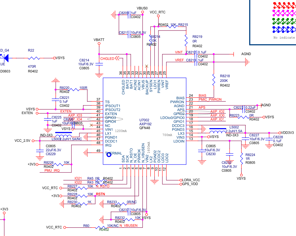
Just the "simple" task of turning on the T-Beam is perhaps a little more complicated than what I'm used to from a microcontroller board. It includes a fully blown Power Management Integrated Circuit (PMIC) chip, which has 3 LDO linear regulators and 3 DC-DC buck converters, controllable over i2c.
The chip is an X-Power AXP192, which unfortunately I can't find a full English datasheet for, however I have found enough resources to get by. This is the same PMIC used in the m5stack modules, so there is a fair amount around.
The things I've been using are:
Alongside the PMIC itself, we need to know how its voltage rails are wired in to the components on the board. Annoyingly, the first hit on Google seems to go to the wrong GitHub repo. This one appears to have the correct schematic and example code: https://github.com/Xinyuan-LilyGO/LilyGO-T-Beam
The board seems to have been designed with a few different options in mind, with various components not populated. It's not entirely clear from the schematic what is to be expected from the board, so I spent some time checking out the various circuits.
On my board, things are wired like so:
| Power Rail | Voltage | Net name + Components |
|---|---|---|
| LDO1 | 2.5 V fixed (it seems like maybe this is different for different versions of the AXP192, but I can't find any information on that) | VCC_RTC Only powers GPS backup battery |
| LDO2 | 1.8 - 3.3 V variable | LORA_VCC Powers the LoRa module |
| LDO3 | 1.8 - 3.3 V variable | GPS_VDD Powers the GPS module (2.5 - 3.6 V) |
| DCDC1 | 0.7 - 3.5 V variable | VCC_2.5V Despite the name, this powers the 3.3V pads on the header pins |
| DCDC2 | 0.7 - 2.275 V variable | Not Connected |
| DCDC3 | 0.7 - 3.5 V variable | +3V3 Powers the ESP32, is on by default at powerup. Annoyingly, this also feeds the ESP32's RTC power supply, so we can't power off the rest of the ESP32 whilst keeping the RTC on. |
In addition to the AXP192, there's a discrete LDO 3.3 V regulator, which just powers the on-board CP2104 USB-to-Serial converter from the USB bus. As far as I can tell, this isn't connected at all when running on battery power, so it shouldn't leech any unnecessary power.
I grabbed tuupola's library and the ESP32 IDF and got started. I ran into a few issues with the way tuupola's library uses build system #defines to set register defaults, and it didn't give me the level of control I was hoping for, so I've forked it and will see about merging my changes back when I'm happy with it: https://github.com/usedbytes/axp192
I did run into one slightly embarrassing issue by accidentally disabling DCDC3 as the first thing my code did when the ESP32 boots - that immediately powers of the ESP32, and made it a little tricky to re-flash good code. I had to spam the reset button and hope that the flashing tool managed to get in just before the bootloader jumped to my buggy code. I think there are pins I could use to force the chip to stay in the bootloader if I got really stuck, but I managed to get some good code back on after a couple of attempts.
With my modifications to the library, I could quickly start controlling all the different power rails, and got the GPS powered up and outputting data - so we're off to a good start.
    // Power off everything we don't need
    axp192_set_rail_state(&axp, AXP192_RAIL_DCDC1, false);
 axp192_set_rail_state(&axp,...
Read more »
This project started out from the intersection of a couple of threads:
Towards the end of 2019, I went to a talk about LoRaWAN by @rwhb2: https://rwhb.me/talks/lorawan-ttn-talk.pdf, and (relatedly) at around the same time some LoRa gateways started getting set up around Cambridge where I live. This sounded like a pretty cool technology which I was keen to have a play with.
Then a little later I heard from Digitspace, who were interested in sponsoring a project with products from their store. They have a pretty good selection of kit in a variety of categories - one of which is an array of different LoRa boards.
I found the T-Beam board, which has LoRa and GPS, making it a good candidate for a self-contained LoRaWAN mapper, which isn't very original but seems like a reasonable first LoRa project. I've also been interested for a while in trying to track road quality while cycling, and this board looks like a reasonable fit for that too - an 18650 battery gives a good amount of capacity, the GPS means it can track the position without needing an external source of location data, and an accelerometer can be easily added.
Digitspace were kind enough to send me a free voucher for the two main parts of this project:
In return, I agreed to write up the project here. It looks like makers are free to submit their own requests for sponsorship via their website.
The Digitspace store seems pretty good. They have plenty of selection, and from what I can tell it's almost all maker-friendly open-source gear. At the moment, the product pages don't have a whole lot of information on them, but because the designs are open you can find it via your favourite search engine.

Which one? I haven't made any changes with respect to antennas, just using what it came with.
There's a sheet metal WiFi one on the board, and external GPS and LoRa antennas.
 TheBestJohn
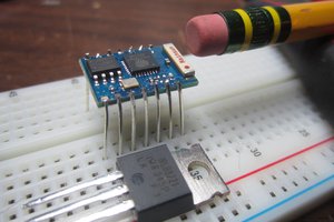
 Hari Wiguna
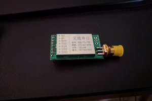
 Dominic DeMarco
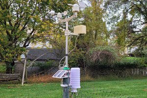
 Kevin Kessler
I see you are using an external antenna. What did you have to do to to the board to enable this please? it looks like some resistors need moving around. Thanks.