Stefan Wagner
Indicator LEDs:
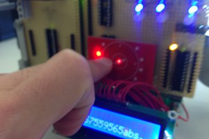
- steady blue - station is powered
- steady red - tip temperature has not reached setpoint yet
- steady green - tip temperature is at setpoint - iron is worky
- blinking red/green - iron is in sleep mode - move handle to wake up
- steady red and green - iron is in off mode - move handle to start again
For calibration you need a soldering iron tips thermometer. For best results wait at least three minutes after switching on the soldering station before you start the calibration. Calibrate at your prefered temperature using the trimpot.
Choose a power supply with an output voltage between 16V and 24V which can provide an output current according to the table below. The power supply must be well stabilized. The current and power is determined by the resistance (R = 8 Ohm) of the heater.
| Voltage (U) | Current (I) = U / R | Power (P) = U² / R |
|---|---|---|
| 16 V | 2.00 A | 32 W |
| 17 V | 2.13 A | 36 W |
| 18 V | 2.25 A | 41 W |
| 19 V | 2.38 A | 45 W |
| 20 V | 2.50 A | 50 W |
| 21 V | 2.63 A | 55 W |
| 22 V | 2.75 A | 61 W |
| 23 V | 2.88 A | 66 W |
| 24 V | 3.00 A | 72 W |
In addition to the components for the PCB you will need the following:
- 3D-printed case
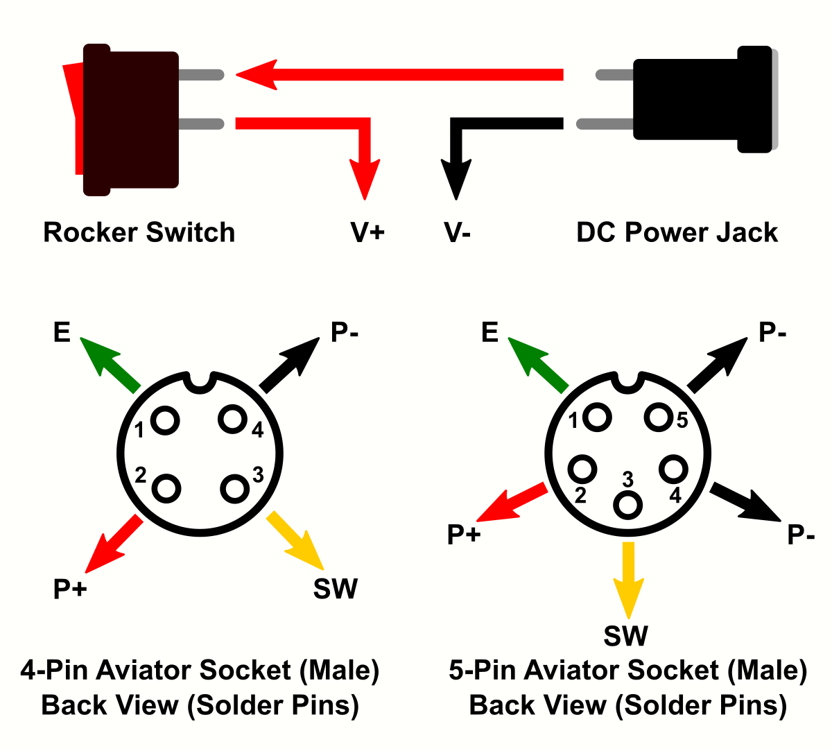
- Aviator Plug (4- or 5-pin depending on your iron handle)
- DC Power Jack (5.5 * 2.1 mm)
- Rocker Switch (KCD1 15 * 10 mm)
- Some wires
- 4 Self-tapping screws (2.3 * 5 mm)
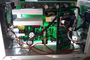
Make sure that all parts fit nicely into the case. Solder the wires to the connectors and protect them with heat shrinks. Use thick wires (AWG18) for the power connections. Make all connections according to the schematic down below. Solder the wires directly to the corresponding pads on the pcb. Upload the firmware and screw the pcb on top of the case.
 Dave_ Z.
 mircemk
 shenzhen