Close
0%
0%

LED Stand Lighting - Sound Reactive - ESP8266

Sender/Receiver LED Sound Reactive Light Stands ESP8266 Arduino (No longer using a SP107E)

Similar projects worth following
Use a sender unit to listen with a midcrophone and send the volume data to 4 slave units. Each slave unit will have 1m of WS2812b 144/m strip LED's. The data will be collected by a master D1 Mini ESP8266 WiFi board and then transmitted to 4 receiving D1 Mini boards. Each unit will be powered by an 18650 3.7v battery rechargeable through a 5v 2A power supply.

This project started by essentially copying Nerdforge's video on Youtube https://www.youtube.com/watch?v=yninmUrl4C0&t=16s

Kinda got it working although I struggled with the coding side as his code did not work for me. Then I looked around for some more example patterns including some in the Arduino examples directory for the ESP8266. So we were off.

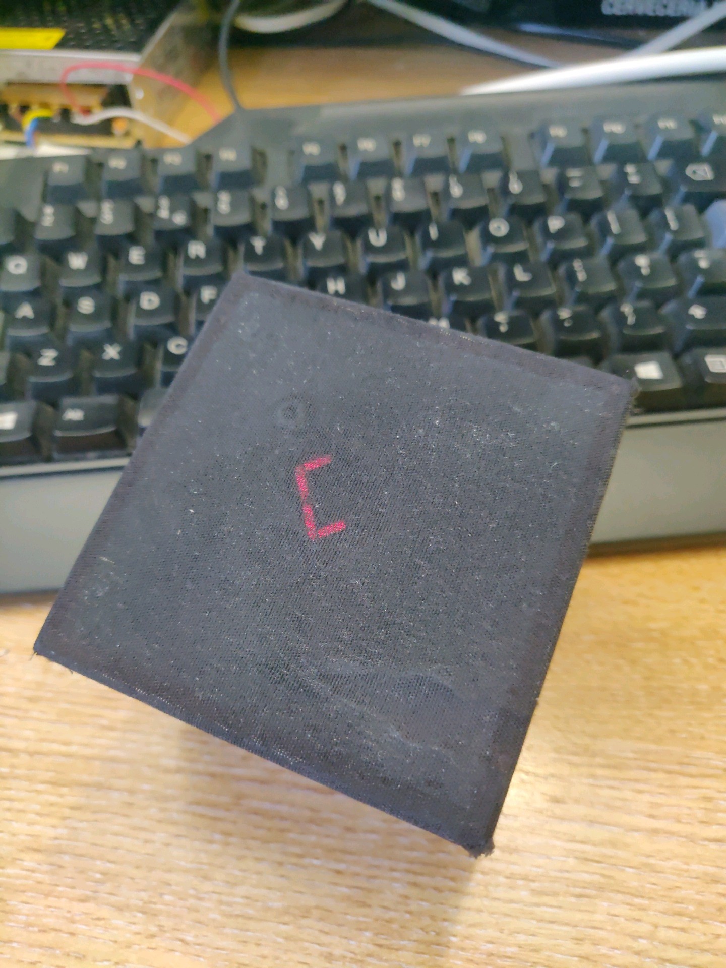
Initially I used a basic pattern library and could select different patterns by clicking a button under the black cloth on the master. There is also a microphone under the fabric listening to sounds. The data received from the microphone was sent via WiFi. All the patterns were stored on the slave units, which is OK. There are some slight differences between the slaves output and they can get out of time with each other as they receive the data from the microphone at slightly different times from the master.

Then, I remembered I had a SP105 LED controller and thought how easy it would be to use that in the master, read the data it was producing and transmit that to the slave units. Then all the slave units needed to do is react to the data it is receiving. Well, I fried the SP105, so, I bought a few SP107E LED controllers as they had sound reactive built in.

This is where I have got to. I am trying, unsuccessfully right now, to read the data from the SP107E and transmit it to the slave units so they react to the output recorded at the master.

If anyone has the experience and can point me in the right direction, please contact me. In the meantime, I will keep exploring the options.

  • 5 × D1 Mini ESP8266 WiFi board
  • 4 × WS2812b 144 LEDS/m LED Strips Each strip is 1m in length
  • 1 × 16x2 LCD Screen
  • 1 × Rotary Encoder
  • 5 × 18650 3.7v Battery and holder

View all 11 components

  • All change again.

    Ron O'Sullivan07/13/2020 at 10:14 0 comments

    Reading the data from the SP107E has proven extremely difficult. The coding side is a little outside my current capabilities.

    I have continued with the project but back to how I was originally building it. I have updated it slightly by using a 16x2 LCD display and creating a menu system to change pattern, brightness, speed and fade, and added an encoder for selection.

    I have used many patterns from the examples for FastLED. I have used Fire2012 by Mark Kriegsman but with code modifications to make it sound reactive (the brightness and the height the flames go based on volume, its a great effect with the right song). I have used many of Marks patterns, including Pride2015, which I prefer over the Rainbow patterns.

    I tried to include some matrix patterns as these provide a nice split effect to the upright LED tape, but struggled to make it work. Again, my limited coding experience didn't help here. I also tried to use FFT and FHT but these are not very compatible with ESP8266 D1 Mini boards.

    I will post some more pictures of the finished product.

  • Possible breakthrough

    Ron O'Sullivan05/25/2020 at 21:36 0 comments

    OK, I think I have figured out how to read the data now. Timing is key.

    The WS2812b LED strips I am using have very specific timing requirements for the data being sent up the data line.


    So reading the SP107E output is just a matter of determining what is happening in the period of time to send, as per these timings.

    But I think if you take a measurement at say 2us and one at 6us, then you can determine what status the LED should be in.

    If the reading at 2us is LOW then the data being sent is the RESET code. No need to read the next position at 6us as RESET is all it can be. If the reading is HIGH, then take a reading at the 6us position. If the reading is HIGH then the bit can be set to 1 else it will be 0. We can build the 24bit segment for each LED and then send it to the Slave D1 Minis and use FastLED to show the pattern. Not sure how much latency there will be.

    Just need to code this now. 

  • LED Stand Lighting - Log

    Ron O'Sullivan05/24/2020 at 19:08 0 comments

    Master prototype.

    Base of master.

    Inside slave

    Four slave units. One with external battery connected. (Proof of concept, 8 hours running on full charge, but only on 60 LEDs)

View all 3 project logs

Enjoy this project?

Share

Discussions

Similar Projects

Does this project spark your interest?

Become a member to follow this project and never miss any updates