Close
0%
0%

Retro-PixelBoy

Handheld Retropie gaming console based on CM3+ and DPI screen

Similar projects worth following
A PCB, a parts list and some 3D files to make a powerfull retro handheld console which can run emulators up to PS1, N64 and PSP.

All the files for this project can be found on Github : https://github.com/pep3175/Retro-PixelBoy

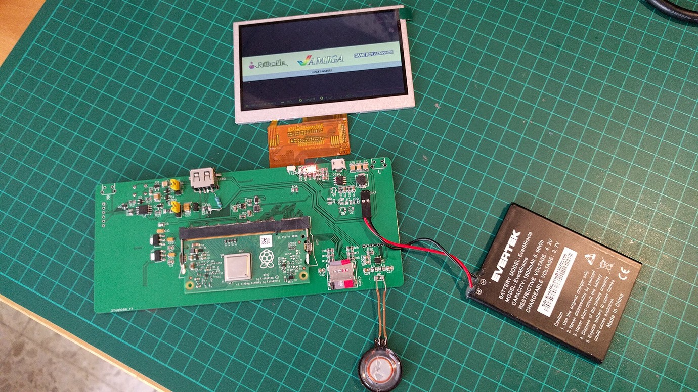
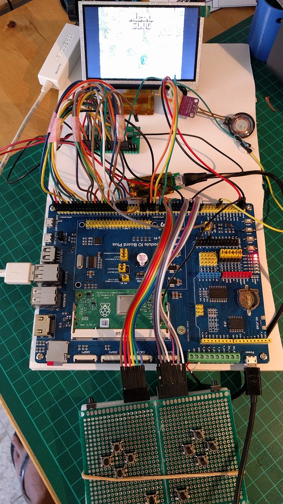
This is a handheld console based on a raspberry pi and running Retropie. Yeah, one more...

Indeed, this is a kind of DIY projects that is quite successful on the Internet. It is also my third project of this kind

and this time my attention was focused on the following points :

    - the Screen
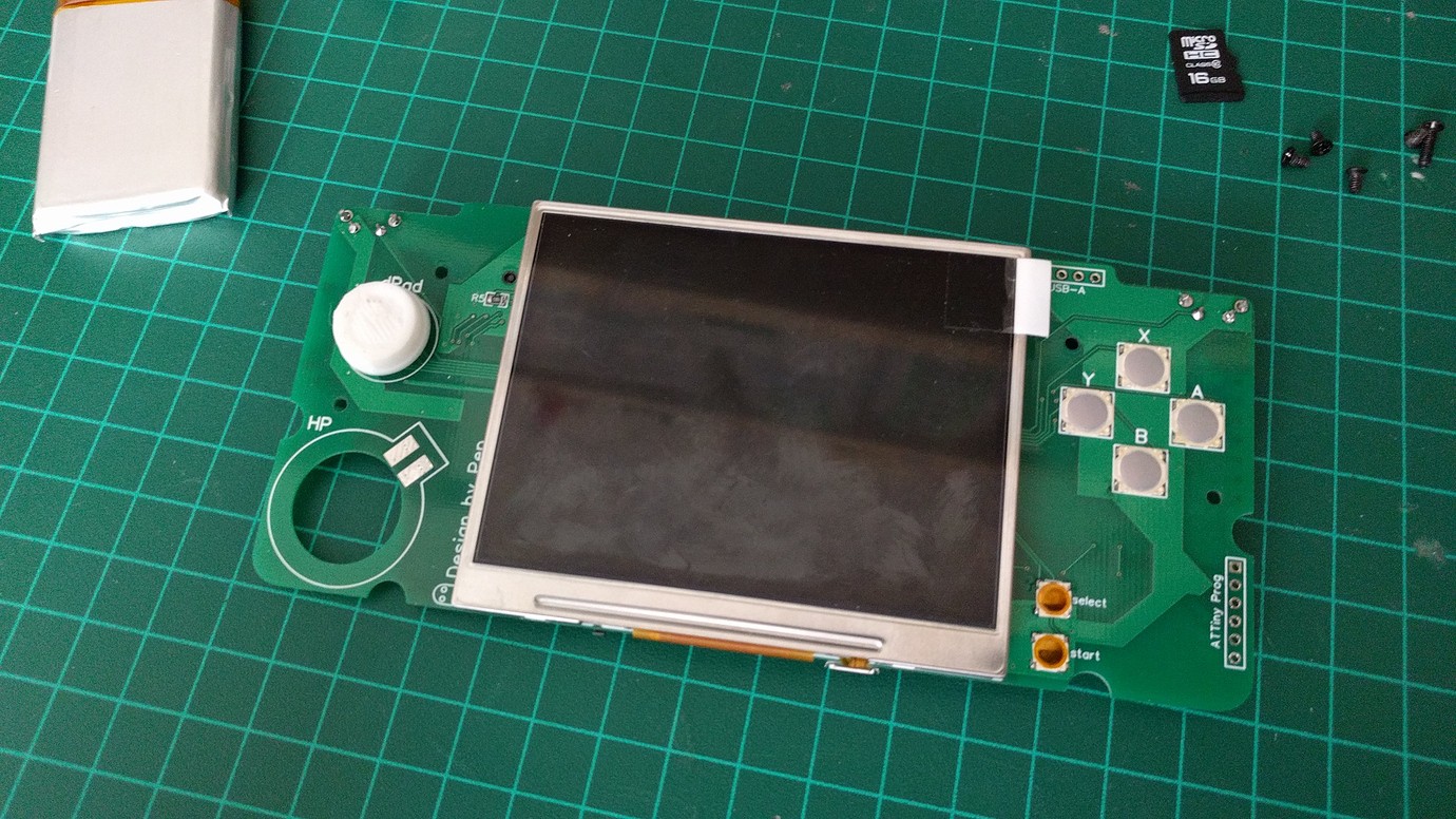
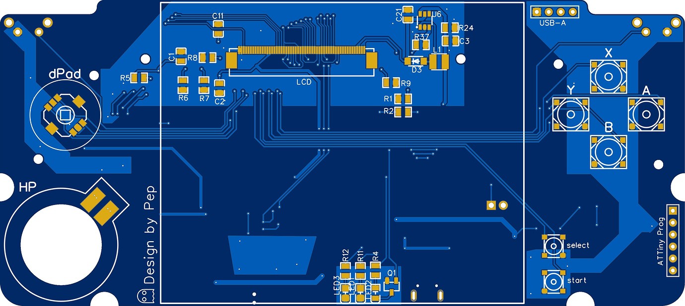
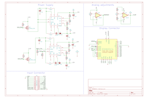
    My 1st project used the SVideo output of Pi and the 2nd used the SPI interface. The quality with SVideo is really low whereas with the SPI interface, it's the performance that suffers. So I decided to use the Raspberry DPI (RGB) interface which is already a bit less common. The advantage of the DPI is the speed of display (60Hz), a good image quality (it is digital and not analog like SVideo), and the possibility to drive the display directly by the Raspberry without any additional component. The down side is that uses a lot of GPIO. It depends on the chosen mode but for 24 bits (8 bits per RGB component) you already need 24 GPIO for the data.

    - the Raspberry Pi
    My intention is to build a device that is as portable as possible, so I'm trying to limit the size. Moreover, I don't want to cut up an existing card. This puts aside the RPI3, I don't want to be bothered by unnecessary ports. I really like the RPI zero for its compactness but it is still a bit tight in terms of power and limits the usable emulators.
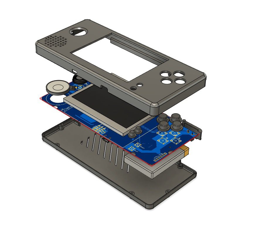
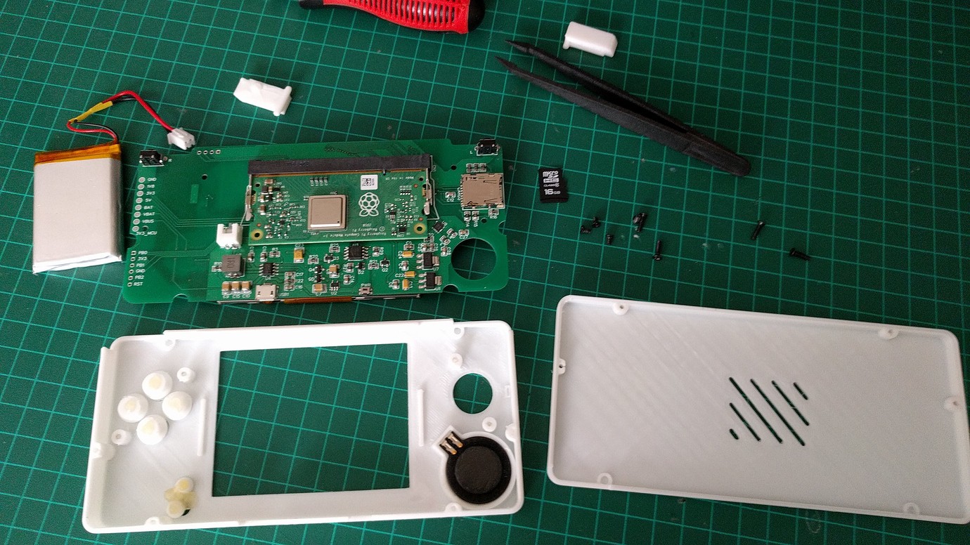
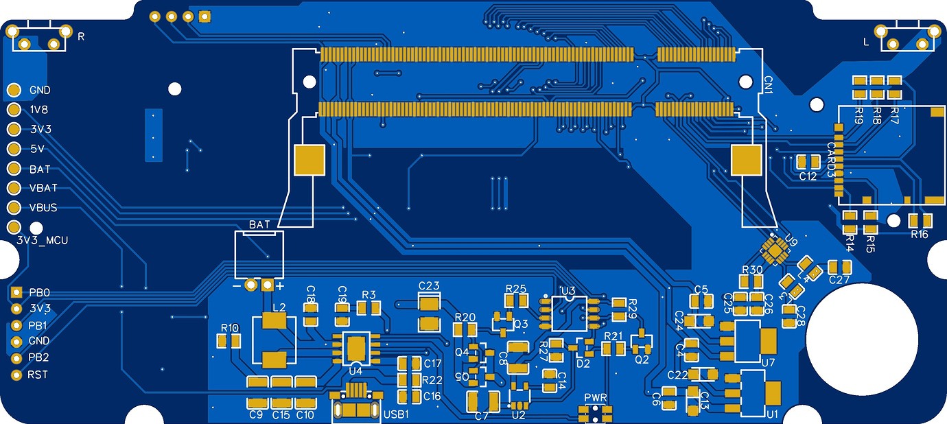
    So I went for a Raspberry CM3+ which has the power of the Raspberry 3 while allowing a good integration. The console's size is 147x68x18 mm. An other good point for the CM3 is the large number of available GPIOs. Indeed, and contrary to the other Raspberry, on the CM3 all the GPIOs of the BCM2837 are available.

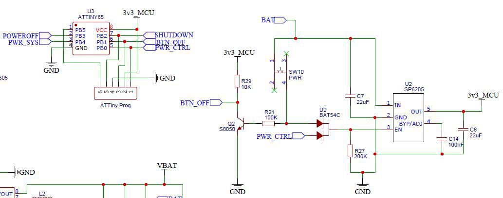
    - starting and shutting down
    Another thing that bothered me in my previous projects, and in most of the ones I find on the Internet, is the fact that the power management is totally disconnected from the Raspberry. This results in the need to initiate a software shutdown of the system and then once the Pi is off, to cut off the power to the device. I wish to have a behavior like a standard console, i.e.: pressing the PWR button in the OFF state turns the device on and starts the system, the same thing in the ON state starts a clean shutdown of the Pi and cuts the power off.
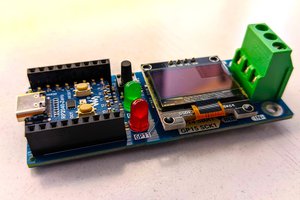
    For power management, I use an ATtiny85 microcontroller. Its GPIO number is just what I need for this purpose, its size is contained and it doesn't need any crystal or other components to run.

    - the Sound
    I have always been a bit disappointed by the sound outputs via PWM on Pi zero. I tried to make bandpass filters but the result never reached my expectation. On this project, I want something more qualitative, so I decided to use a DAC. I used the Adafruit breakout board based on the MAX9357 circuit and I found it particularly adapted to this kind of use. So, I made my DAC based on the same integrated circuit.

  • 1 × LQ035NC111 3.5" TFT LCD 320*240 resolution
  • 1 × Raspberry pi CM3+ Electronic Components / Misc. Electronic Components
  • 1 × 1473005-4 DIMM Connectors DDR2 SODIMM 200P for CM3+
  • 1 × ATtiny85 Microprocessors, Microcontrollers, DSPs / ARM, RISC-Based Microcontrollers
  • 1 × MAX98357 QFN16 DAC audio amplifier

View all 10 components

  • Some videos

    Pep317506/29/2020 at 15:55 0 comments

  • 3D printing and assembly

    Pep317506/29/2020 at 15:47 0 comments

    Once the PCB has been modeled in Fusion 360, the other elements have to be made of in order to be able to make a box with the right dimensions. For that, I search as much as I can on the Internet for the 3D files of my components and modules and when I can't find them, I measure the size and make myself a basic model allowing me to report the main dimensions on which to rely.

    Of course, I don't need all the elements of the device. The most important elements are : the screen, the battery, the USB port, the switches and the HP.

    Here what it looks like :

    This is not the most recent rendering and I have already made some new modifications such as the rear vent allowing a better dissipation of the heat produced by the processor.

    3D modeling should always be done with the print in mind. Indeed, not every model is printable and keeping in mind the way a 3D printer works when one is designing the 3D model gives better results.

    Concerning the soldering of the components, it is clear that a heat gun is more than recommended. I also used a stencil to deposit the soldering paste for the DDR2-SODIMM socket that will host the CM3. There are still 200 pins and after facing some difficulties to solder it on the first prototype, I preferred to make my life easier for this time and get a much better rendering.

    In the end, the different elements are ready for assembly :

    I use a drop of hot glue under the buttons to get a good contact with the switches.

  • PCB

    Pep317506/29/2020 at 15:35 0 comments

    For my final PCB, I went on ALPS SKRRABE010 switches which I'm really fan of the feeling. For the D-Pad, I wanted to use an ALPS SKRHAAE010 multi-directional switch also for the feeling it provides. It reminds me of the NeoGeo Pocket Color which is a console that I particularly liked for this point.

    Here is the rendering of the PCB after routing:

    Once this part was completed, it was therefore necessary to wait for the PCB to be received. However, the modeling of the case could begin. The first thing to do was to make the PCB in Fusion 360 from the images above.

  • Power supply

    Pep317506/29/2020 at 15:31 0 comments

    Concerning the power supply, I chose an integrated circuit used in the power bank: IP5306.

    The purpose of the IC is to manage the charge, discharge and protection of the LiPo battery but also to boost the voltage to 5V. The voltage supplied by the battery varies from 4.2V to ~2.8V depending on its charge. Moreover, this IC allows to drive up to 4 LEDs to indicate the battery charge level.

    The CM3+ requires 3 different voltages to operate correctly : 5V, 3.3V and 1.8V. The documentation also mentions a 2.5V voltage but this one is only mandatory for the composite video output which I don't use.
    So I start from the 5V voltage and use voltage regulators to obtain the 2 others.

    To power the backlight of the screen, I need to power 6 LEDs in series. So I need a higher voltage for this module: ~19V. For that, I use a boost-converter based on the IC PT4103.

    For the power supply part, I followed the IP5306 datasheet recommendations and made a first PCB to test the chosen options.

    From there came out:

        - you have to be careful with the implementation of the screen connector. Yes, on this version, I reversed it... :smile:
        - I need a pulldown resistor so that the IP5306 will shut down once the system is off.
        - the 4 LEDs to know the battery charge status are not useful. 2 LEDs are enough to know the state of charge or discharge.
        - other little things that are not worth mentioning here.

    I have also added jumpers to this PCB in order to be able to isolate certain parts of the circuit and thus more easily track down problems.

    This prototype was also the occasion for me to refine the ATtiny code and to test in real conditions boot and power-off sequences of the system.

    Finally, I was able to start the work on the final PCB.

  • Boot sequence

    Pep317506/29/2020 at 07:31 0 comments

    To be able to control the start and shutdown of the future device, I decided to use an ATtiny85.

    The microcontroller is connected to the battery via the PWR button. When the PWR button is pressed, the ATtiny85 is powered and it starts.

    The code of the ATtiny is very simple. Once started, it waits for about 2 seconds and then turns the PWR_CTRL pin HIGH which activates the voltage converter U2 and powers the ATtiny. The loop is closed, the PWR button can be released, the ATtiny remains on.

    Then, the code sets the PWR_SYS pin HIGH, which will turn on the whole system and thus the Raspberry.

    Once the boot sequence is over, the code scans the use of the same PWR button, using the BTN_OFF pin, and the state of the POWEROFF pin. When BTN_OFF goes LOW for about 1.5 sec, the SHUTDOWN pin is switched to HIGH which orders the Raspberry to poweroff (overlay shutdown).

    Once the Rasbpberry shutdown sequence is completed, the Raspberry switches the POWEROFF pin to the high state and the ATtiny shuts down the whole system by cutting the PWR_SYS and PWR_CTRL pins (the latter has the effect of shutting down the ATtiny itself).

  • Configuring Raspberry pi

    Pep317506/28/2020 at 15:34 0 comments

    The first 22 pins of the RPI are used for the 18-bit DPI interface of the screen (6 per color plus 4 for clock, signal and position).

    4 are defined for the I2S interface for sound (I only need 3)

    12 are used for controls (4 direction buttons, 4 action buttons, 2 triggers and start/select)

    2 will be used for power management

    Beyond the created dt-blob.bin file, I call in my config.txt file different overlays to complete my config :
       - i2s-gpio28-31 and hifiberry-dac: to send the sound in PCM format to the DAC.
       - gpio-shutdown: so the raspberry can warn that it's done shutting down.
       - gpio-poweroff: to order the raspberry to shut down...
       - gamepad: this one is an overlay I created so that the use of the GPIOs dedicated to the controls simulate the keys of a keyboard.

  • Audio

    Pep317506/28/2020 at 15:32 0 comments

    For the sound, as indicated in the "details" section, I use the Adafruit "MAX98357 I2S Amp Breakout board" and a Gameboy SP speaker. It's a digital to analog decoder and also an amplifier and allows to directly connect a mini speaker.

    The amplifier can deliver up to 3W depending on the impedance of the loudspeaker, the power supply used and the tolerated distortion. It can be supplied with a voltage between 2.7 and 5.5V.

  • First experimentation

    Pep317506/28/2020 at 15:22 0 comments

    I started my experiments with the WaveShare compute module IO board. It gives me access to all the board's ports in a quick and easy way. I was then able to validate the different modules I wanted to use (except for power supply).

    The most important of them is the screen. It was clearly not easy to find the display that suited me. I had to spend a lot of time on Aliexpress to ask for information from the sellers in order to get reliable features. It was also necessary to study the documentation of these displays in order to fully understand how they work and adapt the configuration of the Raspberry accordingly.
    Indeed, I use on this project the DPI interface of the Raspberry which is a simple parallel interface that sends the color data of each pixel at the same time on all the ports. The more ports we use, the more accurate the color will be.

    The Raspberry can go up to 24 bits but I preferred to settle for 18 bits to keep enough GPIO available for the other features. The interface is controlled by the GPU and we use the config.txt file to adapt the output to the screen characteristics.
    I tried several displays and ended up choosing a 3.5" 4/3 format which is easily found on the Internet : LQ035NC111.

    I also made myself a small game controller to be able to carry out the first tests.

View all 8 project logs

  • 1
    Order the PCB

    Use the gerber files to order the PCB from the company of your choice. You'll also find the schematics that will allow you to modify some aspects and route your own PCB if wishes.

  • 2
    Order the components

    Use the BOM file to order the electronics parts from the company of your choice.

    The specific parts, like the screen or replacement parts for GBA SP, can easily be found on Aliexpress.

  • 3
    Populate the board

    Start the soldering with the DDR2 socket. This is the trickiest part if you don't use a stencil and a heatgun.

    The second difficulty is the MAX98357A IC, which is a QFN part and is easier to solder with a heatgun.

    The remaining of the bottom side can be done with solder iron. Finish this side before starting the other.

    On the top side, the difficulty is the LCD connector which is easier to solder with heatgun.

    Resistors and capacitors are 0805 which are easy to solder by hand.

View all 6 instructions

Enjoy this project?

Share

Discussions

Similar Projects

Does this project spark your interest?

Become a member to follow this project and never miss any updates