 EK
EKThere is new progress following yesterday’s experimentation. It looks like a possible solution will be a magnetic wiper extending across the length of the enclosure. This can be coupled to an exterior wiper. The exterior wiper would pivot a bracket that would be holding the buoy to the spool box. Once it rotates to a specific angle, the buoyancy of the buoy will release it from the hold to its destination of the surface of the water. Here’s a look at the experiment result that output that idea:

To reach this idea, there were iterations that built on each subsequent experiment. Let’s take a look at them.
Read on for all the info
Following on from yesterday, time to test with the stronger (taller) magnets. These were enclosed into a 3D printed shell so they could be glued to a variety of surfaces for quick testing. The petal piece was attached to the servo horn. The bottom right shows a problem that was starting - the magnets were attaching to each other and making it difficult to be spread apart.
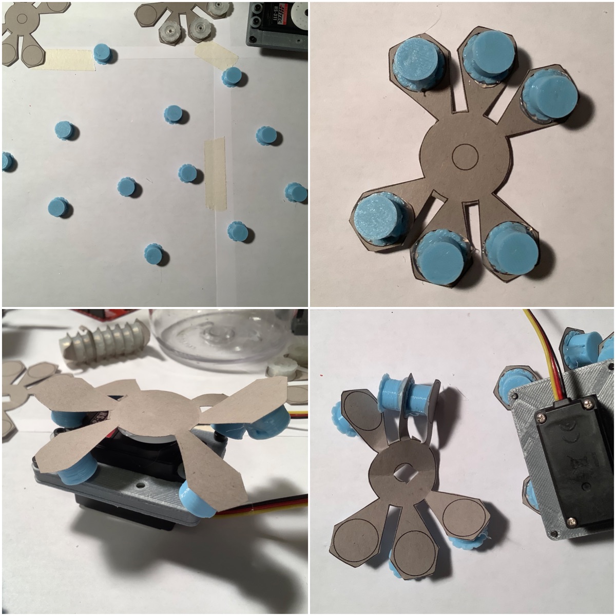
It fit into the enclosure, however with some unsuccessful fidgeting to unstick the magnets from each other, it became clear this wasn’t going to work. The number of petals were reduced to 4. This worked for one side (bottom left), however for the other side, the magnets were attracted to the screws more than the external petals (bottom right).

This idea was clearly not working. Onto the next, which was using the outer wall as the surface, instead of the bottom. To prototype this, made some servo horns out of cardboard and attached the magnets to it. The first try worked, then improved it by adding bends.

Here’s what happens when one of the magnets on the interior disconnects:
Next up was to try making this stronger. This was done by adding an array of magnets.
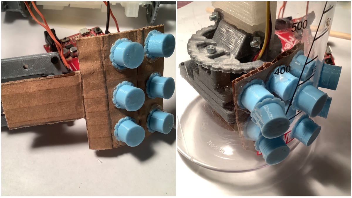
Here’s what the result looked like:
To modify this even more, the polarity of the magnets was swapped for every 2nd magnet. This meant that the adjacent magnets were not repelling each other anymore, but instead attracting.

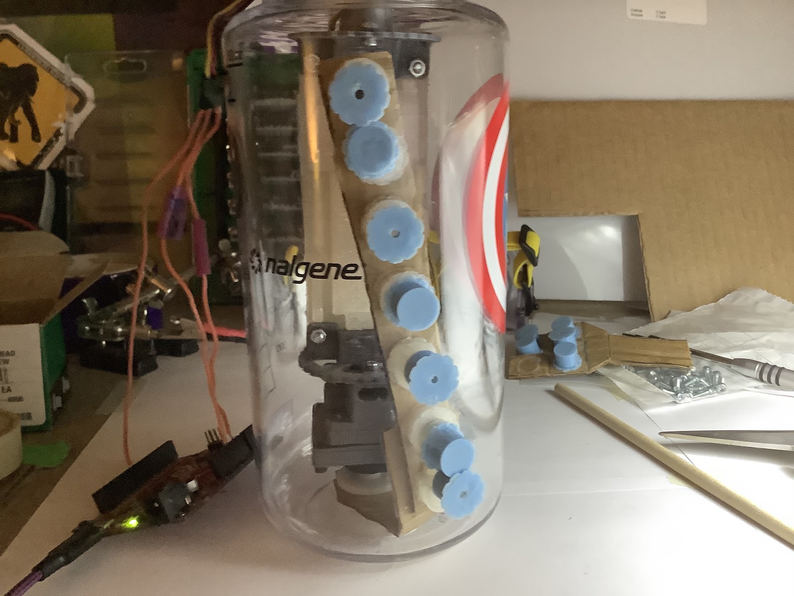
Here’s what the result looked like installed:

Here is the video of that in action:
The moment when realizing this idea was heading in the right direction is seeing two magnets that disconnect, and there is enough force that they are able to reconnect.
There was a shortcoming to this idea, which is that it’s going to be difficult for it to be an entire “seatbelt” for the buoy against the buoyancy force unless it is covering the entire length of the enclosure. This observation is where the wiper idea originates from. A long strip of magnets, alternating their polarity, which attaches to a similar long strip externally.

Here it is in action:
My hypothesis was that the upper portion of the wiper would lag behind the lower (where it is closer to the servo horn being driven). This was proven true. One way that this effect could be mitigated is to have a perpendicular piece from the wiper extend to one of the stages in the buoy’s construction. This piece could rest in a groove that would support it as it moves along. Additionally, this would be made from rigid PLA, not bendable cardboard. There’s not very many spare millimeters for the buoy stages, so some tinkering and 3D print iteration will be needed to find where it can fit…!
It’s a relief to have a new idea to try after this promising experiment! As you can see, the key to reaching this idea was building on the iterations previous, and this was a relatively fast process compared to CAD modelling -> 3D printing -> assembly.
The next steps will be to try the perpendicular piece sliding on one of the stages idea; in order to validate that it would reduce the lagging at the upper portion. As well as making some of the other pieces in rigid plastic, to remove those as variables in this issue.
Other updates: the 2nd iteration of the onboard gateway enclosure is complete. PCBs are here, and additional electronics are here too. The next steps there are to solder the onboard gateway, and verify the dimensions fit for the enclosure. Then, 3D printing of that can commence in order to send to Leo and Tobi. Electronics pcbs next steps …….. sanitizing the box, opening the package, and sanitizing the boards. Then photos will be shared!
Discussions
Become a Hackaday.io Member
Create an account to leave a comment. Already have an account? Log In.