land-boards.com
-
SD Card Data Wrong?
07/25/2020 at 12:00 • 0 commentsNote I figured this issue out in a later log.
Bottomline - If the first block has 0x00 at location 0x000 then it's NOT a bootable SD image and the only thing that can be found in the record is the location of the First Partition Table at location 0x1BE-0x1C0.
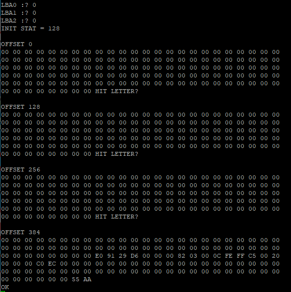
The data from the SD card looks like:
The data should be:
![]()
The 0x55AA at the end matches. Not all SD sectors have this signature field. Not sure why I am not grabbing the right data.
-
BASIC Program to Read SD Card
07/24/2020 at 12:15 • 0 commentsFrom the SD card VHDL code:
-- Wait until SDSTATUS=0x80 (ensures previous cmd has completed)
-- Write SDLBA0, SDLBA1 SDLBA2 to select block index to read from
-- Write 0 to SDCONTROL to issue read command
-- Loop 512 times:
--     Wait until SDSTATUS=0xE0 (read byte ready, block busy)
--     Read byte from SDDATA
First cut at a sector dumper in BASIC:
 100 REM OSISDOS PROTOTYPE READ SD CARD IN BASIC
 120 DT=61456:REM SDDAT
 130 ST=61457:REM SDSTATUS/SDCONTROL
 140 A0=61458:REM SDLBA0
 150 A1=61459:REM SDLBA1
 160 A2=61460:REM SDLBA2
 200 L0=0:REM FIRST SECTOR LOWEST ADDRESS BYTE
 210 L1=0:REM FIRST SECTOR MIDDLE ADDRESS BYTE
 220 L2=0:REM FIRST SECTOR HIGHEST ADDRESS BYTE
 230 INPUT "LBA0 :";L0
 240 INPUT "LBA1 :";L1
 250 INPUT "LBA2 :";L2
 300 POKE A0,L0:REM WRITE ADDRESS REGISTERS
 310 POKE A1,L1
 320 POKE A2,L2
 400 SC=PEEK(ST):REM LOAD AT INITIAL STATUS, S/B 128
 410 PRINT "INIT STAT =";SC
 420 POKE ST,0:REM WRITE 0 TO CONTROL REG FOR READ BLOCK
 425 FOR J=0 TO 3:REM FORMATTED OUTPUT
 427 PRINT
 428 PRINT "OFFSET";128*J
 430 FOR I=0 TO 127
 440 SV=PEEK(ST)
 450 IF SV <> 224 GOTO 440:REM WAIT FOR READ VALUE READY
 460 DV=PEEK(DT)
 470 GOSUB 600
 480 NEXT I
 482 IF J=3 GOTO 490
 485 INPUT "HIT LETTER";Z$
 490 NEXT J
 500 END
 600 REM PRINT NUMBER AS HEX
 610 NB=(DV AND 240)/16
 620 GOSUB 650
 630 NB=DV AND 15
 640 GOSUB 650
 642 PRINT CHR$(32);
 645 RETURN
 650 IF NB>9 GOTO 700
 660 VL=NB+48
 670 PRINT CHR$(VL);
 680 RETURN
 700 VL=NB+55
 710 PRINT CHR$(VL);
 720 RETURN
-
FAT32 File Format
07/21/2020 at 11:29 • 0 commentsWhen you search google for FAT file format you get tons of pages on formatting disks. It's harder to pull out the detailed format of the SD card. Wikipedia to the rescue (Design of the FAT file system). A less technical FAT32 Wikipedia page is File Allocation Table. Here's a helpful page in the references at the end of the Wikipedia page (The FAT filesystem).
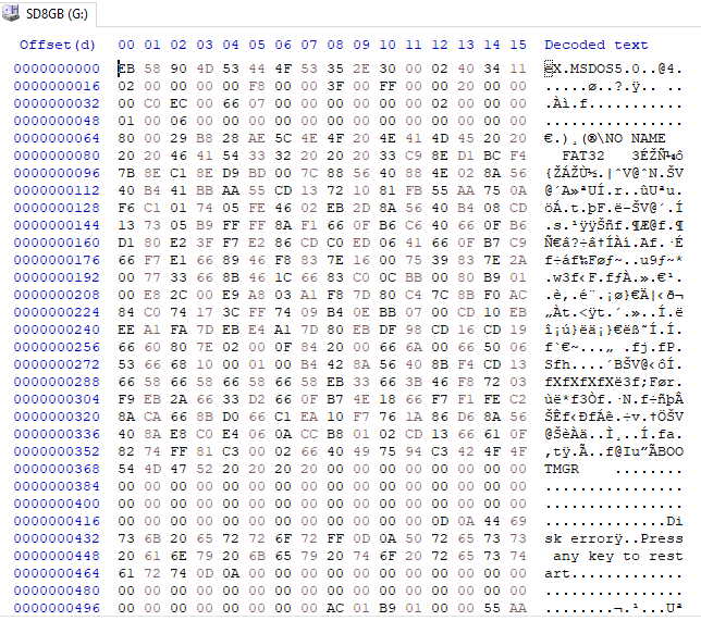
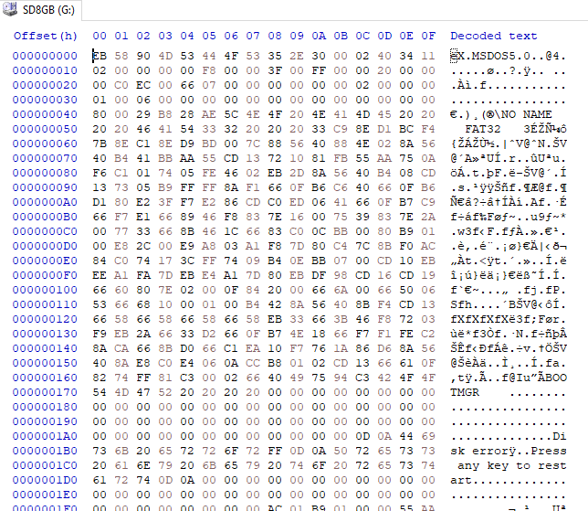
I used my PC running Windoze to format an 8GB SDHC card. I can view the raw data on the card using HxD (How to use HxD as Disk Editor to save Sectors as Binary Files). Here is what the boot sector (first sector on the SD card) looks like:
.From the page (The FAT filesystem):
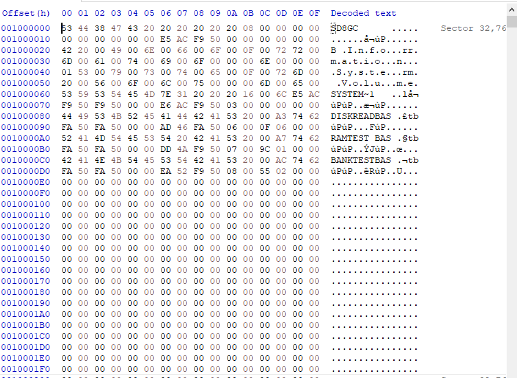
Here the FAT32 version of the boot sectors. Values from HxD <>.

Bytes   Content
0-2     BS_jmpBoot
        Jump to bootstrap (E.g. eb 3c 90; on i86: JMP 003E NOP.
        One finds either eb xx 90, or e9 xx xx.
        The position of the bootstrap varies.
        <0xEB5890>
3-10    BS_OEMName
        OEM name/version (E.g. "IBM  3.3", "IBM 20.0", "MSDOS5.0", "MSWIN4.0".
        Various format utilities leave their own name, like "CH-FOR18".
        Sometimes just garbage. Microsoft recommends "MSWIN4.1".)
        <"MSDOS5.0   ">
        /* BIOS Parameter Block starts here */
11-12   BPB_BytsPerSec
        Number of bytes per sector (512)
        Must be one of 512, 1024, 2048, 4096.
        <0x0200> = 512
13      BPB_SecPerClus
        Number of sectors per cluster (1)
        Must be one of 1, 2, 4, 8, 16, 32, 64, 128.
        A cluster should have at most 32768 bytes.
        In rare cases 65536 is OK.
        <0x08> = 8 sectors per clusters
14-15   BPB_RsvdSecCnt
        Number of reserved sectors (1)
        FAT12 and FAT16 use 1. FAT32 uses 32.
        <0x083a> = 2106 decimal
16      BPB_NumFATs
        Number of FAT copies
        <0x02>
17-18   BPB_RootEntCnt
        Number of root directory entries (224)
        0 for FAT32.
        <0x0000> = 0 root directory entries
19-20   BPB_TotSec16
        Total number of sectors in the filesystem (2880)
        (in case the partition is not FAT32 and smaller than 32 MB)
        <0x0000>
21      BPB_Media
        Media descriptor type
        <0xF8> = Non-removable media
22-23   BPB_FATSz16
        Number of sectors per FAT (9)
        0 for FAT32.
        <0x0000> = FAT32
24-25   BPB_SecPerTrk
        Number of sectors per track (12)
        <0x003F> = 63 decimal
26-27   BPB_NumHeads
        Number of heads (2, for a double-sided diskette)
        <0x00FF> = 255 decimal
28-31   BPB_HiddSec
        Number of hidden sectors (0)
        <0X00002000>
32-35   BPB_TotSec32
        Total number of sectors in the filesystem
        <0X00ECC000> = 15,514,648 sectors (8GB)
36-39   BPB_FATSz32
        This field is the FAT32 32-bit count of sectors occupied by ONE FAT.
        Sectors per FAT
        <0x00003BE3> = 15331 dec
40-41   BPB_ExtFlags
        Mirror flags
        Bits 0-3: number of active FAT (if bit 7 is 1)
        Bits 4-6: reserved
        Bit 7: one: single active FAT;
               zero: all FATs are updated at runtime
        Bits 8-15: reserved
        <0x0000>
42-43   BPB_FSVer
        Filesystem version
        <0x0000>
44-47   BPB_RootClus
        First cluster of root directory (usually 2)
        <0x00000002>
48-49   BPB_FSInfo
        Filesystem information sector number in FAT32 reserved area
        (usually 1)
        <0x0001>
50-51   BPB_BkBootSec
        Backup boot sector location or 0 or 0xffff if none (usually 6)
        <0x0006>
52-63   BPB_Reserved
        Reserved
64      BS_DrvNum
        Logical Drive Number (for use with INT 13, e.g. 0 or 0x80)
        <0x80>
65      BS_Reserved1
        Reserved - used to be Current Head (used by Windows NT)
        <0x00>
66      BS_BootSig
        Extended signature (0x29)
        Indicates that the three following fields are present.
        <0x29>
67-70   BS_VolID
        Serial number of partition
        <0xD086111A>
71-81   BS_VolLab
        Volume label
        "NO NAME   "
82-89   BS_FilSysType
        Filesystem type ("FAT32   ")
        "FAT32   "
The old 2-byte fields "total number of sectors" and "number of sectors per FAT" are now zero;
this information is now found in the new 4-byte fields.
An important improvement is the "First cluster of root directory" field.
Earlier, the root directory was not part of the Data Area, and was in a known place with a known size,
and hence was unable to grow. Now the root directory is just somewhere in the Data Area.
The signature is found at offset 510-511.
This will be the end of the sector only in case the sector size is 512.
FirstDataSector = BPB_RsvdSecCnt + (BPB_NumFATs * BPB_FATSz32) + RootDirSectors;
= 2106 + (2 * 15331)
= 32,768
The sector there is:
-
Fast CPU Select
07/21/2020 at 11:16 • 0 commentsGrant has a Fast CPU selection which allows the user to press the F1 key to toggle between Slow and Fast CPU choices.
0 (power-up default) will set the CPU to 1MHz (standard UK101 speed). Pressing the F1 key will switch it to 12.5MHz ( ! ) and pressing F1 again will switch it back.
It patches the CEGMON location that does the timing loop for the repeat key. It's worth installing. A 12.5 MHz UK101/Ohio Scientific C1P is pretty cool.
-
Fixing CEGMON Issues
07/21/2020 at 10:33 • 0 commentsMy CEGMON source didn't work when it went to scroll the screen. Grant's original CEGMON code worked just fine so I suspected a difference between my assembled code and Grant's code.
To find the difference in the 2 KB file I did a CEGMON dump from the monitor itself and dumped it into a file. I then replaced the ROM code with the original CEGMON code and dumped it to another file.
I saved the two files as CSV files and loaded them into EXCEL (actually Libre Office spreadsheet) and compared the two files. That gave me a few locations which were different and I changed my source code to get it to match Grant's original CEGMON code. The differences were in the area of the screen addresses. It looks like the source file I was using was probably for a 2KB screen memory.
And it worked! No more scrolling problems.
I uploaded the source code to GitHub.
![]()
-
Moving CEGMON to ROM
07/16/2020 at 12:28 • 0 comments[Path_To_RetroAssembler]/retroassembler.exe -d cegmon.bin cegmonDis.asm
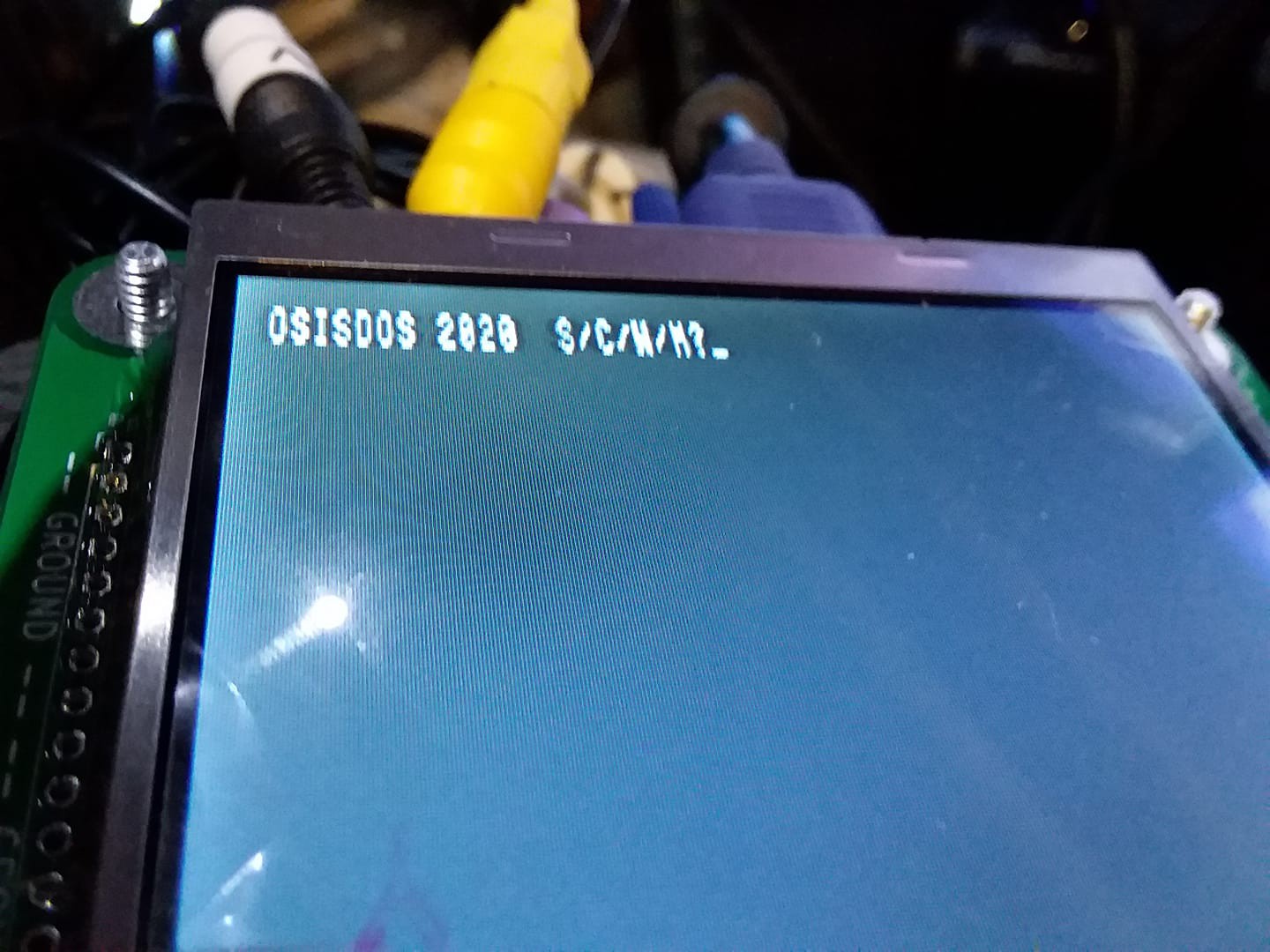
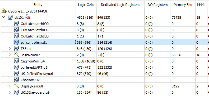
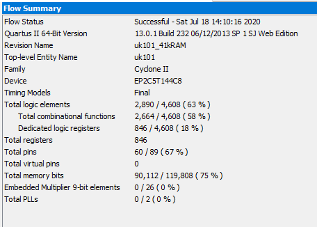
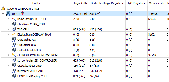
The SD Card uses the following FPGA resources:
The overall resources show 98% of the logic is used.
It might be worthwhile to free up some of the logic elements so it's not so tight. Part of that is due to Grant placing the CEGMON and character ROMs into logic instead of memory. He did that in order to have a minimal build with 4KB of SRAM available. With external SRAM the SRAM is now available for use by the card. So CEGMON and/or the character ROMs could be put into the FPGA as ROMs.
A better reason to move CEGMON to ROM is it's easier to work on the code if it's more easily assembled and loaded to the FPGA.
Assembler/Compiler Toolchain
I tried using the cc65 toolchain to produce the ROM file but ran into roadblocks. Although cc65 does have a lot of different outputs I couldn't convince it to produce S-Record or Hex output files.
I went to a 6502 group on Facebook and someone suggested retroassembler. It compiled the code and created a binary output. The command line is:
[Path_To_RetroAssembler]/retroassembler.exe cegmon.s -O=bin
I viewed the binary file in HxD and verified that it seemed to match the source file (sampled a few lines).
retoroassembler even has handy disassembler in which can disassemble source code. The command line to run the disassembler is:
[Path_to_RetroAssembler]/retroassembler.exe -d cegmon.bin cegmonDis.asm
The binary file needs to be converted a .MIF file. I've used the srec_cat utility in my 68000 in an FPGA card design and it does the job nicely. The command line is:
[path_to_srec_utils]\srec_cat.exe cegmon.bin -Binary -o cegmon.mif -MIF
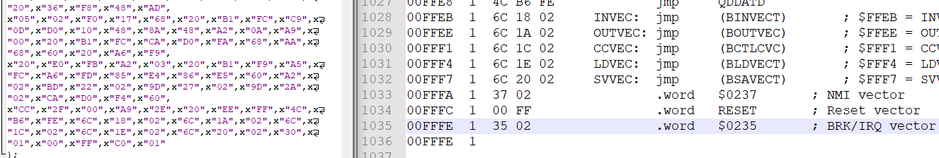
The result didn't run so I compared the code that was generated byte-by-byte against Grant's SEGMON. There were some differences. For instance, there were differences for the NMI and BRK/IRQ vectors at the end of the code:
The CEGMON source has the NMI at 0x0237 but the FPGA ROM file has NMI at 0x0130.
CEGMON source file has BRK/IRQ at 0x0235 but the FPGA ROM file has BRK/IRQ at 0x01C0.
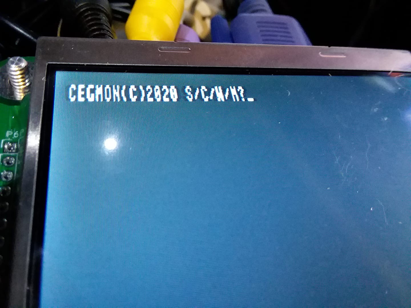
I found a few other differences and after some messing around was rewarded with the CEGMON display.
I was then able to tweek the source code and re-compile. Here's what I was rewarded with:
![]()
Resources
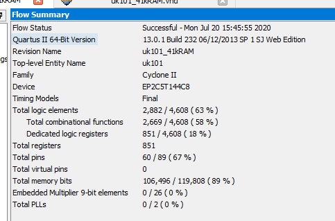
The result of the above was also a reduction in logic resources in the FPGA.
Bigger EPROM
I bumped the ROM size to 4KB leaving enough room (hopefully) to create the SD Card OS/driver. This leaves the modified CEGMON from $F800 to $FFFF and adds space for an SD card driver from $F000 to $F7FF. Since there is I/O from $F000-$F0xx, I've further reduced the new space so the new CEGMON ROM replacement goes from $F100-$FFFF.
This results in more space for logic and higher SRAM utilization.
The detailed breakdown by function is:
If I can get the SD Card to work, it could be useful to take the BASIC out of ROM and load it into the external SRAM from the SD Card.
-
Hardware / Memory Map
07/16/2020 at 11:27 • 0 commentsHardware
Runs on Cyclone II EP2C5 Mini Dev Board using Land Boards EP2C5-DB card which adds:
- 128KB SRAM (not all usable without some paging scheme)
- Composite video connector
- PS/2 keyboard
- Serial port (can connect FTDI USB to serial)
Design is based on Multicomp UK101 FPGA project with Multicomp elements (both) by Grant Searle.
Adds High Speed SD card interface from mc1024 project.
Memory Map
Address Range Function 0x0000-0x9FFF 40KB SRAM
(Contiguous space viewable from BASIC)0xA000-0xBFFF 8KB BASIC in ROM 0xC000-0xCFFF External SRAM (not viewable by BASIC) 0xD000-0xD3FF 1KB Display RAM 0xD000-0xD7FF 2KB Display RAM (Not used) 0xDC00-0xDFFF Scanned Keyboard (PS/2 replaces) 0xE000-0xE000 Banked SRAM
16 banks of 4 KB0xF000-0xF001 ACIA Serial port 0xF002-0xF003 J6 I/O 0xF004-0xF005 J8 I/O 0xF006 LED 0xF010-0xF017 SD Card Control/Status/Data Registers 0xF100-0xF7FF OSISDOS ROM 0xF800-0xFFFF 2KB CEGMON ROM SD Card Interface
SD Card addresses are:
Address Register 0xF010 SDDATA - Read/write data 0xF011 SDSTATUS - Read
SDCONTROL - Write0xF012 SDLBA0 - Write-only 0xF013 SDLBA1 - Write-only 0xF014 SDLBA2 - Write-only From the SD Controller VHDL file comments:
For both SDSC and SDHC (high capacity) cards, the block size is 512 bytes
(9-bit value) and the SDLBA registers select the block number.
SDLBA2 is most significant, SDLBA0 is least significant.

For SDSC, the read/write address parameter is a 512-byte aligned byte address.
ie, it has 9 low address bits explicitly set to 0.
23 of the 24 programmable address bits select the 512-byte block.
This gives an address capacity of 2^23 * 512 = 4GB ..
BUT maximum SDSC capacity is 2GByte.
To avoid the addressing differences between SD and SDHC cards, I am going to use SDHC cards. These are greater than 2 GB (typically 4 GB cards) but can be as large as 64 GB. Hard to imagine there's that many GB of OSI / UK101 code out there.
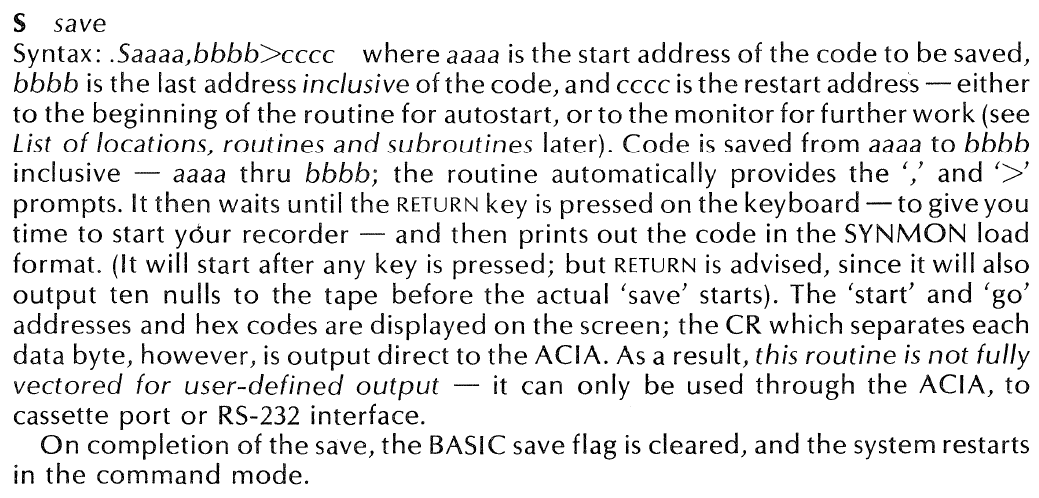
OSI SD Card Operating System (OSISDOS)
Ohio Scientific / UK101 SD Card based Operating System under Multicomp FPGA Computer