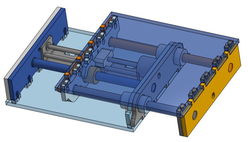
(to start with the end: this evolved into a sub-project and how-to included by reference when building the mill)
Here’s an Onshape model of Minamil's linear slide mechanism generalized for generality:
| pmc's cheap linear slide |
See the README tab, which refers back to a couple of log entries here for:
Please don't expect to have it working two minutes off the laser cutter. Assembly is not really trivial and still really under-documented. Working on it. Things that make it less trivial include: no template for the backlash-adjuster-locking spring yet (but a bit of tape will work) and the inconvenience that you can't build two halves and stick them together because the halves capture each other. That and ordering parts.
The mill is three of those, so a complete for-publication model shouldn’t be far behind. Modulo Christmas. And other stuff. So not promising super-soon. But working on it...
Update 11 Jan 2021
Writing this to get it out of my head for now but revisit later: for modeling these parts I've used a semi-arbitrary minimum feature size of 3mm. For example, the clamps keep 3mm material across the tops of the bearings -- a stressed area. Minimal features like that will be stronger in thicker material and weaker in thinner material. In principle, the minimum dimension could shrink with thicker material and should grow with thinner material. But meh. But some stressed features shrink with thinner material and grow with thicker material and that creates a perverse ~quadratic weakening with thinner material. While that's not great, I don't promise thinner material will be great, so meh.
But I've come up with a simple solution -- "simple" apart from re-refactoring the CAD again which I should stop thinking about for now. The current design starts with the working parts in the middle of the "sandwich", then adds "bread" of variable thickness to each side. If the top-to-bottom thickness of the "sandwich" holds constant, then the space in between decreases with thicker material and increases with thinner material, and the height of the perpendicular end plates may increase/must decrease accordingly. So endplate area can vary inversely with material thickness; and minimum feature size -- in the plane of the material -- can vary with area available; and minimum feature cross sectional area can stay closer to constant across a range of material thickness. As a beneficial side effect, the constant exterior dimension would simplify making anything into which one of these units should fit.
In other news:
Better (i.e. some) assembly doc, handwheel configurations for more general generality, simplified stacking, and easier generation of cut vectors from variable parameters coming "soon". Sooner if I stop thinking about this...
I checked the first try at handwheel slides with a dial indicator and got some astonishing (to me) results. More about that "soon" -- if warranted after I get a build from this model and an indicator together.
 Paul McClay
Discussions
Become a Hackaday.io Member
Create an account to leave a comment. Already have an account? Log In.